Data Bucket-Based Fragment Management for Solid State Drive Storage System
2021-01-23WeiJiangJunLongWangJinYuZhanJingHuanYuHaiBoHu
Wei Jiang | Jun-Long Wang | Jin-Yu Zhan | Jing-Huan Yu | Hai-Bo Hu
Abstract—The current storage mechanism considered little in data’s keeping characteristics.These can produce fragments of various sizes among data sets.In some cases, these fragments may be serious and harm system performance.In this paper, we manage to modify the current storage mechanism.We introduce an extra storage unit called data bucket into the classical data manage architecture.Next, we modify the data manage mechanism to improve our designs.By keeping data according to their visited information, both the number of fragments and the fragment size are greatly reduced.Considering different data features and storage device conditions, we also improve the solid state drive (SSD) lifetime by keeping data into different spaces.Experiments show that our designs have a positive influence on the SSD storage density and actual service time.
1.lntroduction
Fast storage devices are receiving lots of attention from researchers in recent years.The rapid increase in data processing and storage is creating new challenges for current big data processing[1]and storage technologies[2].Many companies have strived to address these challenges in various ways[3], such as Google is using the big data technology to improve its current database performance, and Facebook is focusing on improving the petabyte scale technology.
Fragment formation is always a problem in the storage field.Due to limitations of the modern computer technology, it is hard to avoid fragments in any storage system.Without an appropriate fragment processing mechanism, a lot of storage spaces may be wasted.The current effort on the fragments is to decrease their sizes and improve the related algorithm to limit the fragment appearance rate.In [4], Fuet al.proposed a method to limit fragments by using historic information to judge data in processing.Xiaet al.improved the classical content-defined chunking technology to accelerate duplicate data identification in [5].Zhanget al.proposed a low overhead file system in [6].Luet al.proposed a model to minimize fragments in Android and other mobile devices in [7].They also provided a more accurate analysis method to estimate fragment generation by any old or emerging applications (APPs).Rajuet al.used a novel data structure to reduce data fragment generation on some key-value store database applications in [8].Moreover, in [9], Harvey and Pointon focused on the fragment limitation at mobile web search operations.
When the data size grows into a huge number, it is necessary to quickly process and store these data;otherwise, input/output (I/O) blocks may cause problems on the platform because of excess data.The solid state drive (SSD), flash disk, and other emerging non-volatile memory (NVM) devices have the advantage of high-speed read/write performance, and can maintain data even power-off (i.e., persistence characteristic).Through decades of research and developments, SSD and flash disks have overcome many early-discovered problems.SSD and flash disks are used as the main storage device in many fields instead of the hard disk drive (HDD).Now, the research on SSD, flash disks, and NVM is focused on improving the reading and writing efficiency of data.In [10],Chenet al.studied the non-volatile dual in-line memory module (NVDIMM) based I/O optimization to improve performance of big data processing.Kakoulli and Herodotou proposed a file management system to improve storage performance at different system devices’ capacities and characteristics in [11].Yuanet al.improved the classical write-optimized dictionaries performance on the file system in [12].Ramakrishnanet al.presented a file system, which was specially designed for massive data processing and storing in [13].Santanaet al.showed some unexpected problems, which were emerged at some latest fast and high-performance file systems in [14].Machadoet al.improved the energy efficiency at some low-power servers in [15].Papagianniset al.proposed a stack to enhance system I/O performance on low-latency storage devices in [16].
In this paper, we focus on the storage management optimization.We first examine the file and data set distribution condition on the current storage mechanism, and conclude some shortcomings according to our observation.Based on classical storage management, we introduce a storage manage mechanism, which can greatly reduce data fragments from a random access memory.We focus on improving the storage fully filled rate in any certain range storage space and erasing operation times on storage units of SSD-like random access devices.The main contributions of this paper are listed as follows.
·A new storage unit called data bucket is introduced into the classical data manage architecture for the SSD storage system.
·Two kinds of bucket designs are proposed to modify the current storage management mechanism on the storage manage layout to obtain the best performance.
·The storage space is separated into the erasable zone, and nonerasable zone, such that the hot and cold data can be easily managed in specific ways.
·Extensive experiments are conducted to evaluate the efficiency of our approaches.
2.Real Study on Two Storage Scenarios
2.1.Data Distribution in Two Storage Scenarios
Normally, as the time keeps going, the number of different files will increase at the same time.Especially in server systems, there will be many log files generated every day.Most of them are very small.The system will not hold and create too many files with very big sizes.
We look at a normal home-use computer and an ordinary business server.The home-use computer runs a Windows 7 operation system (OS) on an x86-64 environment.We traced its system data block distribution’s changing condition in three days.The computer will run a script that will be activated every two hours.It will collect the size information of all data blocks and keep them into an a.txt file.During the collection time, the users continue doing their work on this computer as usual.The business server also utilizes the same script to collect data.Due to the massive number of server systems, the interval between two scripts’ activation will be longer than that in the previous home-use computer condition.
2.2.Results
Fig.1 shows the distribution condition changing with time.We can see that the data block increases when the time moves forward.A system consists of more than 150000 data blocks.Most of these are less than 128 KB,mainly from 2 KB to 4 KB.The user activities on a system are not stable, so the blocks generating rate is changed at different time.
Fig.2 presents the size distribution details of a server.Compared with a home-use computer, a server has not only a large number of data blocks but also much smaller blocks—smaller than 1 KB.A server has a space cleaning task in its schedule, so the total number of blocks decreases by Day 3.The operation environment on a server is more stable than that of a personal computer, so the data block increase rate is more regular.

Fig.1.Size distribution on personal computer.
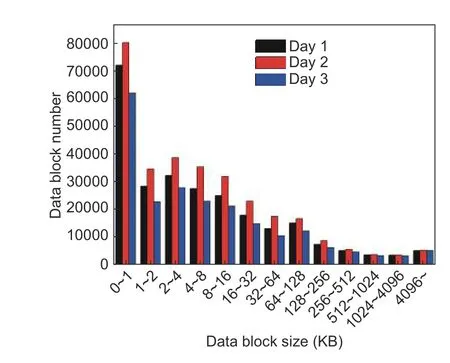
Fig.2.Size distribution on server.
2.3.Preliminary Conclusion
From the above experiments, we can make a simple conclusion: In different hardware and software environments, the distributions of data block sizes are not the same, but show a certain rule in a particular environment, for example, the steady growth of data over time in a web server.The smaller the size of data blocks,the more their number.
It is similar for an ordinary business server and a home-use computer.In the home-use computer, about 45.52% data blocks are smaller than 4 KB, while in the server, this number becomes 56.03%.Moreover, the block size daily distribution curves in home-use computers are not the same, but are similar to each other.This phenomenon also can be found on the data block size daily curve of the server.
3.System Problem and Motivational Example
3.1.System Problem
Current storage devices, including HDD, flash disks, and SSD-like nonvolatile equipment, all use a random storage mechanism to keep files or data blocks anywhere on the entire storage space.This mechanism does little optimization for a specific system, so the fragment problem could be serious.Data can be randomly placed anywhere on the storage space.After that, a fragment, whose size isSfrag, can be produced between two small spaces.Those fragments whose sizes are different to each other are not produced by the system memory alignment mechanism.New coming data can be influenced by these fragments if there is no appropriate solution.
The actual remaining space may be enough for the new incoming data.However, these spaces are separated into different areas.To store the new coming data, we need to perform data slicing or data replacement; otherwise,the system performance may be affected and the efficiency of the storage space usage and the filling rate of every storage spacepfullwill be reduced.
3.2.Motivational Example
The traditional mechanism produces a lot of large-size fragments.However, unlike those memory page fragments, these fragments can be avoided.If we limit the operating range of every data storage operation, the density of data storage will be greatly improved.The size of a fragment between two storage spaces is smaller,and the number of fragments decreases.
Based on the traditional storage mechanism, we manage the storage space by adding an extra data organization group to divide the whole flash or SSD space.When an extra group is not fully filled or not locked by the system, new coming data will continue to write into it.The storage space utilization will increase if the extra data organization group size is appropriately designed.
After we limit the storage operating range into a specific size storage group, the system will first fully fill the current storage space.Because of this, the fragment size between two groups,Sfrag, will be greatly decreased.In Fig.3, the full rate,pfull, is about 30.2%under the traditional mechanism.When adapting our optimization method, the full rate increases to 65.8%,about two times improvement than the original.Moreover, after we put the large files together, the improvement of our new mechanism will be more obvious.The full rate,pfull, changes to 80.1%.
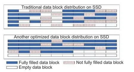
Fig.3.Typical storage unit use on an SSD part.
4.Proposed Techniques
4.1.lmproved Storage Architecture
We present our improvement to the current storage management in Fig.4.The data generated by programs, I/O devices, and remote interfaces will be sent to processing units with the data flow.After processing data, the processing unit OS stores the data with the data block and sends related commands to the storage management system in the storage driver.Here, all data blocks are organized in the new introduced storage group and the data bucket, and then saved on the storage device.The storage system also manages each data block with the data bucket.All relating algorithms operate in the bucket.
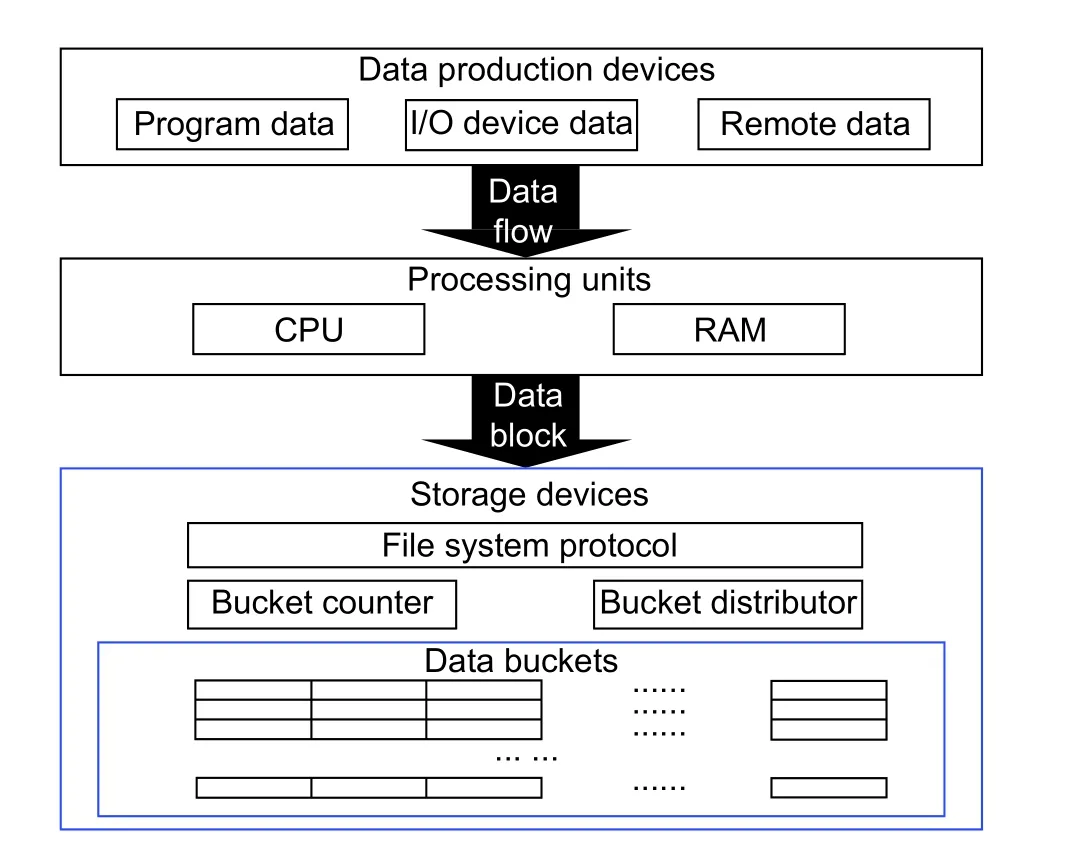
Fig.4.Storage architecture modification.
4.2.Data Bucket Design
Suppose the whole SSD space size isSTotal, and the data bucket size isSbucketthat should be integer multiple ofSTotal.The size of data blocks, which needs to be stored, isS={s1,s2,s3,…,si}.There areNdata blocks in total.The proportion of each block size inNisP={p1,p2,p3,…,pi}.They will first be stored into one bucket.When current bucket is fully filled or there is no space for storing, we keep it in the next one.
Generally, a data bucket should be able to fully keep every data block, which needs to be stored.That is, any data block can be saved in the bucket without additional slicing operations.To ensure the data bucket can satisfy all kinds of data block sizes, the size of the data bucket should meet
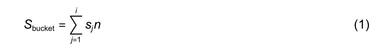
wherenis the number of data blocks, with the corresponding size, which should be kept in the current data bucket.As a feasible bucket size design, which can ensure complete storage for each data block,Sbucketshould be the least common multiple (LCM) of all block sizes.So, (1) will be replaced by

As mentioned above, various sizes of data blocks need to be kept in a data bucket.In addition, the number of data blocks is different.To best feature the block size with the largest number, another possible bucket size design is based on the mathematical expectation of all data block sizes:

whereMis the number of data blocks in a bucket.
4.3.Bucket Manage Algorithm
Zhanget al.indicated that most data blocks in the system at a moment are inherited from earlier time in [6].Only a small number of data blocks are created and modified after an operation.
We divide the whole flash or SSD space into multiple data buckets as an operation unit, just as we designed.After a calculation task is finished, the system will input a list, which includes data blocks to be saved and those to be modified.The storage system decides which data block should be stored in which bucket, based on their characteristics.If one bucket is enough to keep this file, we first search in all used but not fully filled buckets for a bucket with enough remaining spaces to save.Otherwise, the blocks are stored in a new bucket.
Algorithm 1.Data bucket management
1: while all data blocks have not been stored do
2: Load a file from the memory data set list
3: Check the file size
4: if its size is larger than the bucket size then
5: Store or modify it in multiple buckets
6: else
7: Use one bucket to store
8: Check all available buckets’ remaining spaces in the activated-erasing zone
9: if one of the remaining buckets has an enough space to store file then
10: Store the data block in this bucket
11: else
12: Store it in a new bucket
13: Output the storage bucket list
14: Check saved data blocks’ visited information and buckets’ erasing information
15: if visited information larger than the visited window or bucket erasing time larger than the red line then
16: Output this bucket into the nonerasable zone
17: else
18: Output this bucket into the erasable zone
Assume that the storage device space size ranges fromatob, and the basic storage unit size isSunit.Inside the storage space, the size of a limited storage area isSgroup, and it is made up withMbasic units.We set the distribution law: The data kept in one storage unit isp(x).Then, the probability of a unit used,punituse, is
Therefore, the number of used units,Nunituse, in this limited area is
which indicates that the used space in this limited area is

The fragment size in this limited area is
Therefore, the full rate of this area is

For a certain discrete random variable, if the distribution law is the same, the probability can only be influenced by the value range of the variable.In the traditional storage management mechanism, its available space is the whole device space, we set it froma1tob1.The data bucket mechanism will first limit the available space in a small range, it ranges froma2tob2.
Becauseb2<b1anda2≥a1, we can get:b1−a1>b2−a2.As a result,
Comparing the traditional mechanism with the data bucket-based mechanism, the used space in this limited area in our bucket-based design,Suse_bucket, is larger than the old one,Suse_old.The fragment size,Sfrag_bucket, is smaller than the previous design,Sfrag_old.That meansSuse_old<Suse_bucketandSfrag_old>Sfrag_bucket, so

4.4.Zone Management Algorithm
We divide the whole space into the erasable zone or nonerasable zone, according to storage particles’ erasing time in the related data bucket.
·Erasable zone: Keep data, which are new or frequently changed.
·Nonerasable zone: Inside storage particles’ lifetimes are limited.Save old and stable data, or read-only data.
This design will maximize the flash and SSD storage particle utilization.The data in the nonerasable zone and the erasable zone can be reorganized by a user transparent I/O operation.Newly identified cold data is kept into nonerasable zone.Because of this, the visit efficiency of relating data increases.The erasable zone can be divided into the activated erasable zone and inactivated erasable zone.Current read/write (R/W) operations are mostly working in the activated erasable zone.The inactivated erasable zone is transformed to the activated erasable zone if the current activated erasable zone cannot hold incoming data.
After all data is processed, the system decides to keep the data blocks in SSD in the erasable zone block or nonerasable zone block.First, we read the erasing time information of the SSD storage particle.Then we compare it with our pre-setting erasing red line.If the current erasing time is more than that indicated by the red line, this bucket is classified as the nonerasable zone bucket; otherwise, it is classified as the erasable zone bucket.For saved data blocks and their related bucket, we check their access information.If the data is changed often, or is rarely changed and is rarely read and used, it should be grouped into the erasable zone.If the data is not changed frequently but often read, it should be put into the nonerasable zone.
For data in the erasable zone, assumingndata is written or modified in a period and the rate of operations on the same storage unit isp, so the number of superfluous writing isnp.The effectual data erasing number,Nerase, is

Suppose the storage space is made up ofNbasic storage units andMbuckets in the whole device.In the traditional mechanism, to modify or writendata, there should benerasing operations triggered at SSD.Comparing with it, our data bucket mechanism first decreases the total number of erasing units fromNtoM(N>M).This makes the theoretical total erasing time down.Moreover, with the duplication erasing being removed, the number of actual erasing operations in each bucket decreases.
5.Evaluation
5.1.Environment Setup
We use a common home-use computer and an ordinary business services server as the application environment to test our designs.The home-use computer is equipped with Intel Core i7-4770, whose frequency is 3.5 GHz and memory is 8 GB double data rate 4th generation (DDR4) 2400 MHz.We use a 64-GB Kingston SSD as its main external storage device.The server adapts Intel Xeon E5-2670 as its central processing unit (CPU),with the frequency of 2.6 GHz.It has the 32-GB double data rate 3th generation (DDR3) 2133-MHz memory and the same 64-GB Kingston SSD external storage device.Home-use computer is running Ubuntu Kylin 16.04 and some normal personal operations on it.The business server is running CentOS 7.2, providing services to its users as usual.
5.2.Storage Space Full Rate Changes on Different Mechanisms
We first look at the storage full rate of the operating storage space changes under different mechanisms.The system inputs data blocks into the target SSD over time.We use a script to record the percentage of the occupied storage space accounted for the current total operating space, under the proposed storage space manage mechanism.The script activates after a specific number of writes.
Fig.5 shows the changes under various mechanisms in different application environments.We can see that the SSD full rate goes up with the increase in the data block number, under the traditional storage manage mechanism.When input data blocks reach a critical point, the remaining space for SSD is limited.For both the home-use computer and server, adding 240000 or more data blocks to SSD slows down the increasing rate than the previous time.The former input creates many fragments.However, the cleaning and replacement mechanism is unable to make enough spaces for further storage.Thus, additional fragments were put into SSD and fewer spaces were available for the system.In our two kinds of data bucket designs, both in the LCM based design and the mathematical expectation based design, the operating space is limited at the beginning, so the space full rate can stay at a high level, about 90%.In addition, the operating space is increased gradually, with the increase in data, which can cause the space full rate to remain on 93% or more at any time.
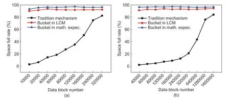
Fig.5.Full rate change in various manage mechanisms: (a) home-use computer full rate change and (b) server full rate change.
5.3.Storage Device Erasing Number Changes through Various Mechanisms
Next, we observe the SSD erasing time changes through the increase in data, under various storage manage mechanisms.The erasing information requires more underlying instructions to read.We programmed a small special program to collect the related information, instead of using a script.We set the lifetimes of all SSD devices in this experiment up to 1000 erasing number, and the red line is 950, because we cannot get the actual erasing number from the manufacturer.The test program listens to and counts the number of data blocks in the system.When the total blocks reach a specific number, the program generates a group of statistical data.
We present our results in Fig.6.The data increases over time, while the SSD total erasing number grows up at the same time.Not only for the traditional manage mechanism, but also for the data bucket mechanism based on LCM or mathematical expectation, the increasing rate of erasing numbers grows steadily.However, the traditional mechanism provides no additional function to prevent some superfluous operations for storage units.An erasing task is triggered in case of new data come or data modification, which keeps the total erasing number at a high level.For a home-use computer with 120000 data blocks, the total erasing number of its SSD can be 4400 or more.For the same block number on a business server, the erasing number can reach 5900 or more.However, in our data bucket design, the delay and bucket unify to avoid some erasing tasks.Almost all erasing happens in the erasable zone.The erasing number on the 12000-data-block home-use computer can be about 210 for LCM and 550 for the mathematic expectation.On a business server, the erasing number can be 280 for LCM and 800 for the mathematic expectation, for the same number of system data blocks.The erasing frequency of SSD is obviously reduced under our data bucket storage management.
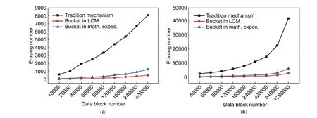
Fig.6.Increasing data influence to erasing number on different bucket sizes: (a) erasing number change in home-use computer and (b) erasing number change in server.
6.Conclusion
In this paper, we have made efforts to improve the storage space fully filled rate, while reducing the fragment size on any storage space at the same time.We introduced two kinds of bucket designs into the system and modified the current storage management mechanism on the storage manage layout to ensure the best performance.We divided the storage space into the erasable zone and the nonerasable zone, so that the hot and cold data could be easily treated in specific ways.The nonerasable zone with cold data had almost no erasing instances, while hot data in the erasable zone can be erased in an organized way.The erasing cost of the storage unit and the system operation time were significantly reduced.
Disclosures
The authors declare no conflicts of interest.
杂志排行

Journal of Electronic Science and Technology的其它文章
- Smart Meter Development for Cloud-Based Home Electricity Monitor System
- Approach for Grid Connected PV Management:Advance Solar Prediction and Enhancement of Voltage Stability Margin Using FACTS Device
- Comparative Study of 10-MW High-Temperature Superconductor Wind Generator with Overlapped Field Coil Arrangement
- Characteristic Length of Metallic Nanorods under Physical Vapor Deposition
- Computational lntelligence Prediction Model lntegrating Empirical Mode Decomposition,Principal Component Analysis, and Weighted k-Nearest Neighbor
- ECC-Based RFlD Authentication Protocol