Microstructure and tensile properties of magnesium nanocomposites fabricated using magnesium chips and carbon black
2020-12-21LeeKim
T.J.Lee,W.J.Kim
Department of Materials Science and Engineering,Hongik University,Mapo-gu,Sangsu-dong 72-1,Seoul 121-791,Republic of Korea
Received 1 November 2019;received in revised form 6 May 2020;accepted 18 May 2020 Available online 26 June 2020
Abstract In this study,carbon black(0,0.01,0.03 and 0.08wt%)and AZ31(Mg-3Al-1Zn)magnesium chips were used to fabricate carbon black-reinforced magnesium matrix composites with extrusion or a combination of extrusion and high-ratio differential speed rolling.After hot pressing at 693K and extrusion at 623K with an extrusion ratio of 22,the magnesium chips coated with carbon black were soundly bonded into a bulk composite material.The grain sizes of the extruded materials were similar with a size of 48.2-51.5μm despite the difference in the amount of carbon black.The yield strength and ultimate tensile strength increased from 177 to 191MPa and from 240 to 265MPa,respectively,as a result of the addition of 0.01% carbon black;however,a further increase in the strength was marginal with additional carbon black.The same trend was observed in the strain hardening behavior.The tensile elongation increased by to the addition of 0.01% carbon black(from 15.8% to 17.4%)due to the increased work hardening effect,but decreased with additional carbon black due to its agglomeration and poor dispersion at higher concentration.After high-ratio differential speed rolling(HRDSR)on the extruded materials and subsequent annealing,the AZ31 and AZ31 composites had a similar f ne grain size of 16.3-17.9μm.The annealed HRDSR composites showed the best mechanical properties at a higher content of carbon black(0.03%)compared to that(0.01%)for the extruded composites.This resulted from the enhanced dispersion effect of the carbon black due to the high shear fl w induced during the HRDSR process.The extruded composites exhibited the three distinct hardening stages(stage II,stage III and stage IV),while the annealed HRDSR composites mainly displayed the stage III hardening.The addition of carbon black increased the strain hardening rate at all the strain hardening stages in both of the extruded and annealed HRDSR materials.At the initial hardening stage,the strain hardening rates of the extruded composites were higher than those of the annealed HRDSR composites,but this became reversed at the later stage of hardening.Possible explanations for this observation were discussed.The strength analysis suggests that dislocation-carbon black interaction by Orowan strengthening and dislocation generation due to a difference in thermal expansion between matrix and carbon black are the major strengthening mechanisms.© 2020 Published by Elsevier B.V.on behalf of Chongqing University.This is an open access article under the CC BY-NC-ND license.(http://creativecommons.org/licenses/by-nc-nd/4.0/)Peer review under responsibility of Chongqing University
Keywords:Recycling;Magnesium alloys chips;Carbon black;Nanocomposites;Extrusion;Differential speed rolling.
1.Introduction
Magnesium alloys,the lightest metals for structural applications,have been studied to improve their mechanical properties by reducing the weight and size of mobile devices for human convenience.
Magnesium recycling protects the environment and saves energy in the magnesium industry.Compared to those for the conventional magnesium remelting process for recycling,solid-state recycling of magnesium scraps and chips has merits,such as reducing the energy consumption,eliminating SF6gas that is the most potent greenhouse gas,as a cover gas to protect molten magnesium from oxidizing in air atmosphere[1]and improving in strength of reproduced magnesium parts due to a reduced grain size[2,3].
Carbon black has been used as a cost-effective rubber reinforcing nanomaterial agent.Carbon black improves the strength and toughness of a rubber and increases the resistance of rubbers against tearing.Carbon black can berecovered from waste tires by pyrolysis[4].The fundamental building block of carbon black comprises spheroidal carbon particles with a size of 10-300nm,which fuse together into chain-like aggregates with a size of 90nm-500nm.Individual aggregates join together by van der Waals forces to form agglomerates.
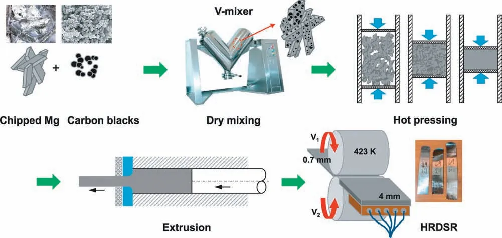
Fig.1.A schematic diagram of the process procedures used in the present work.
There have been a few cases of using carbon or carbon black in metallic alloys.Threrujirapapong et al.[5]showed that a powder metallurgy titanium matrix composite reinforced with carbon black(0.07-0.16wt%),which was prepared by spark plasma sintering and hot extrusion,showed an improvement in the mechanical properties compared to those of pure Ti due to the formation of in situ TiC phase particles as a result of the chemical reaction between Ti and carbon black.Hashimoto et al.[6]showed that AZ91D magnesium alloy chips coated with carbon nanoparticles with a 30nm in particle size could be used to improve the castability of thixomolding process.The tensile strength of a thixomolded magnesium alloy was also improved compared to that of the counterpart without carbon particles.
In this study,we attempted to fabricate magnesium alloy composites reinforced by carbon black using AZ31(Mg-3Al-1Zn)magnesium alloy chips and carbon black as the raw materials for the extrusion and severe-plastic-deformation rolling processes.The fabrication of carbon black-reinforced magnesium composites was difficul through the remelting process because carbon does not wet molten magnesium.High-ratio differential speed rolling(HRDSR)was applied to the extruded materials to improve the dispersion of carbon black in the matrix by imposing high shear stress and large shear strain during the rolling process[7,8].
2.Material and methods-
The chemical composition(wt%)of the AZ31 magnesium alloy was Mg-3.1Al-0·59Zn-0.01Fe-0·002Ca-0·002Cu-0.16Mn-0·004Ni-0·01Si.Fig.1 shows a schematic diagram of the processes used in the present work.Magnesium alloy chips with a size of 1-2mm were prepared from a commercial AZ31 magnesium alloy ingot using a chipping machine.The AZ31 chips were agitated in the presence of 0,0.01,0.03 and 0.08wt% carbon black(0,0.01,0.03 and 0.08vol%,respectively,when the densities of AZ31 and carbon black are assumed to be 1.77g/cm3and 1.8g/cm3,respectively)with an average particle size of 27nm using a V-blender mixer for 2h to induce the adherence of the carbon black to the chip surface.The mixtures of the magnesium alloy powders and carbon black were hot pressed at 693K to produce round billets with a diameter of 75mm and length of 120mm.Then,the billets were hot extruded at 623K with an extrusion ratio of 22 in the form of a plate with a thickness of 4mm.Some of the extruded plates were sliced into plates with a thickness of 3mm and then subjected to HRDSR with speed ratios of 1,2 and 3 at 653K.When the speed ratio is above 2 in HRDSR,severe plastic deformation by shear is expected to occur during the rolling process[7,8].Before rolling,the rollers were preheated to 423K and maintained at that temperature during the entire rolling process.The fina thickness of the rolled samples was 0.7mm,and the total number of rolling passes was 4-6.
Tensile samples with dog bone shapes(with a gauge length of 20mm)were prepared from the extruded plates and rolled plates.The gauge of the samples was parallel to the extrusion or rolling directions.Tensile tests were conducted at room temperature at a strain rate of 1×10⁻³s−1.Three tensile samples were used for each material.
The microstructures of the extruded and rolled samples were investigated by optical microscopy and electron backscattering diffraction(EBSD).For the EBSD measurement in a field-emissio scanning electron microscope,the samples were polished using a 1μm diamond paste and then a 0.04μm colloidal silica.The EBSD data were analyzed with the aid of the TSL software(Version 7.0),which used a tolerance angle of 5° and a confidenc index value>0.1.The EBSD step sizes was 0.2μm.
The microstructures of the rolled materials were also examined by scanning electron microscopy(SEM)and transmission electron microscopy(TEM;JEOL 2100F at 200 keV).The samples for TEM analysis were ground to thin discs,jet polished with a solution composed of 60% methyl alcohol(CH3OH),30% glycerin(C3H8O3)and 10% nitric acid(HNO3),and then ion milled.
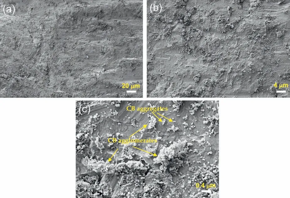
Fig.2.The surface of the chips coated by carbon black(CB)after agitation in the V-blender at different magnifications(a)low,(b)intermediate and(c)high.
3.Results
3.1.Microstructures
Fig.2(a)shows the surface of the chips that were coated by carbon black after agitation in the V-blender.The carbon black appears to uniformly adhere to the chip surface at a low magnificatio(Fig.2(a)and(b)),but there were many places where carbon black agglomerated(Fig.2(c)).
Fig.3(a)shows the optical microstructure of the billet obtained by hot pressing the AZ31 chips coated with 0.08%carbon black.The AZ31 chips were diffusion bonded well during the hot pressing process.The carbon black particles formed layers along the interfaces between the bonded magnesium chips(Fig.3(b)and(c)).According to the energy dispersive X-ray spectroscopy(EDS)mapping results(Fig.3(d)),oxygen was also rich at the interface,which may be due to the presence of an oxide layer on the surface of the AZ31 chips or/and the minor presence of oxygen,hydrogen and nitrogen inevitably contained in the carbon black.
Fig.4(a)-(d)shows the optical microstructures of the extruded materials observed on the longitudinal cross-section planes.The semicontinuous carbon black layers present along the interfaces between the diffusion-bonded magnesium chips in the hot-pressed microstructures were broken into small segments and dispersed along the extrusion direction in the bands.The density of the carbon black particle bands increased as the added carbon content increased.Fig.5(a)-(d)shows the EBSD inverse pole figur(IPF)and grain boundary(GB)maps of the extruded materials observed on the longitudinal cross-section planes.All four materials had recrystallized grains with a fibe texture,with(0002)basal planes//the extrusion direction and〈2110〉+〈1010〉//the extrusion axis.Unindexed regions mostly likely represent the carbon black agglomerates.This is because this region appeared to increase as the amount of carbon black increased and low-angle grain boundaries were developed in the vicinity of these regions.The EBSD maps of the four materials show many{10¯12}twin lamellae in the grains.The average grain sizes of the extruded AZ31,0.01%C-AZ31,0.03%CAZ31 and 0.08%C-AZ31 were 51.5,48.8,50.5 and 48.2μm,respectively,indicating that the effect of addition of carbon black on refinemen of matrix grains is small.
Fig.6(a)-(c)shows the low-magnificatio optical microstructures of the 0.01%C-AZ31 samples after rolling with different speed ratios.In all cases,shear bands and twins formed during rolling.At a speed ratio of 1(i.e.,equal speed rolling(ESR)),the density of shear bands was relatively low,and they were inclined symmetrically across the midplane of the sheet.Higher densities of shear bands were observed in the HRDSR samples and the shear band density increased as the speed ratio increased from 2 to 3.In the HRDSR samples,shear bands in the upper,middle and lower layers were inclined(by∼30°)to the same sign direction.According to the finit element simulation results[7],a larger amount of shear deformation occurs more uniformly at a higher speed roll ratio.During ESR,the increments in the shear strain in the upper and lower layers are identical in magnitude but opposite in sign,and no shear strain occurs at the middle layer;however,during HRDSR,the increment in the shear strain has the same sign in the upper,lower and middle layers,and the increment in the middle layer is the average of those at the upper and lower layers[7].The high-magnificatio optical microstructures of the HRDSR 0.08%C-AZ31 samples with different roll speed ratios are shown in Fig.7(a)-(c),and the GB map and(0002)pole figur of the HRDSR 0.08%C-AZ31 sample rolled with a speed ratio of 3 are shown in Fig.7(d).The density of twins,deformation bands and shear bands tend to increase with increasing roll speed ratio.
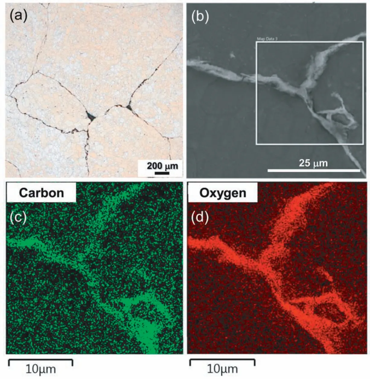
Fig.3.(a)Optical images and(b)SEM micrographs of the billet obtained by hot pressing the AZ31 chips coated with 0.08% carbon black.EDS mapping results for(c)carbon and(d)oxygen.
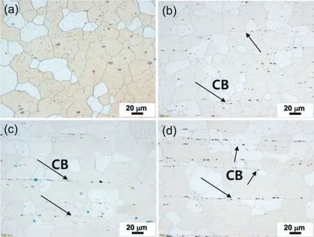
Fig.4.The optical microstructures of the extruded(a)AZ31,(b)0.01%C-AZ31,(c)0.03%C-AZ31 and(d)0.08%C-AZ31 observed on the longitudinal cross-section planes.
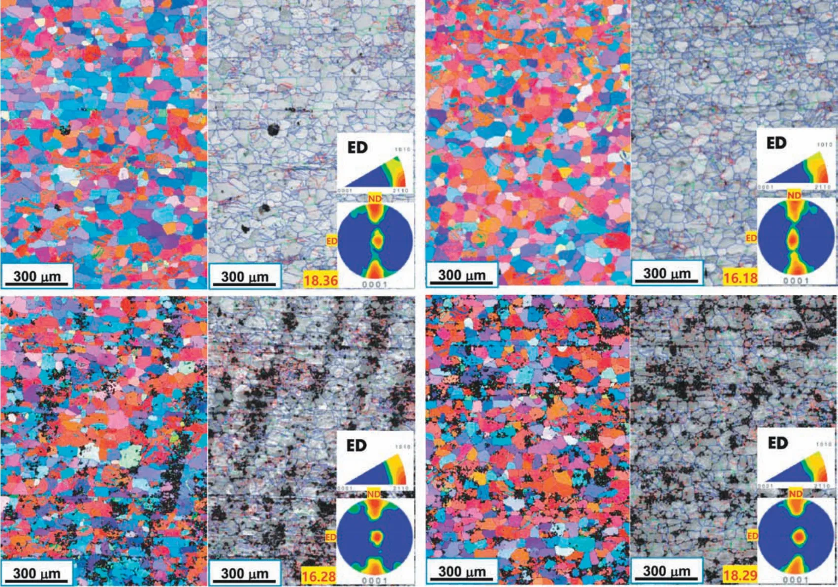
Fig.5.The EBSD inverse pole f gure(IPF)and grain boundary(GB)maps of the extruded(a)AZ31,0.01%C-AZ31,0.03%C-AZ31 and 0.08%C-AZ31 observed on the longitudinal cross-section(TD)planes.In the GB maps,low-angle grain boundaries(2°≤θ<5°),intermediate-angle grain boundaries(5°≤θ<15°)and high-angle grain boundaries(15°≤θ)are represented by red,green and blue colors,respectively.The(0002)pole f gures and ED inverse pole f gures are shown as insets.
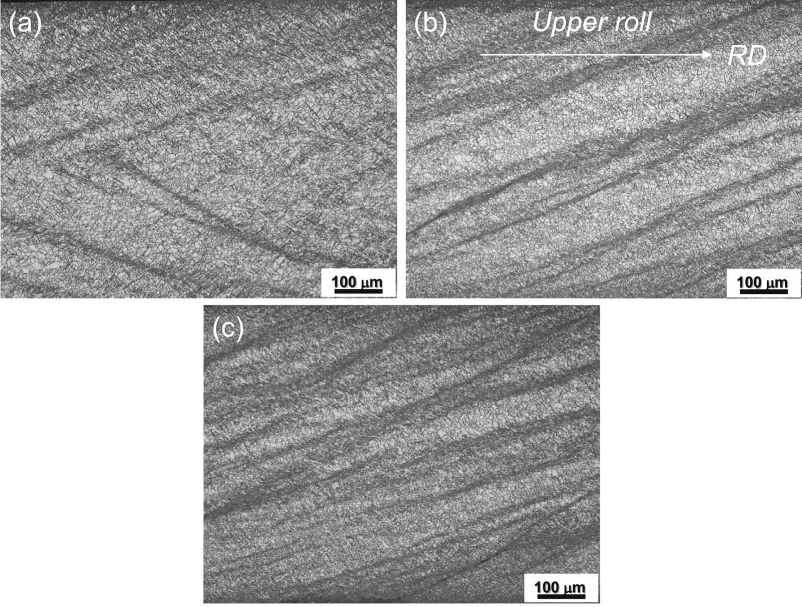
Fig.6.The optical microstructures of the 0.01%C-AZ31 samples after rolling with speed ratios of(a)1,(b)2 and(c)3.
Low-angle grain boundaries were dominant in the rolled matrix,and a strong basal texture developed during rolling(Fig.7(d)).Fine grains developed in the places where the deformation or shear bands intersected each other.Fig.8(a)and(b)shows the TEM micrographs of the 0.08%C-AZ31 sample after HRDSR with a speed ratio of 3.Dispersed carbon black aggregates could be observed and some of aggregate structures appear to have been broken and damaged.Detection of carbon black was difficul even in the HRDSR samples during TEM observation because the added amount of carbon black was small,and they were not uniformly dispersed.
Fig.9(a)-(d)shows the optical micrographs of the HRDSR samples rolled with a speed ratio of 3 after annealing at 623K for 1h.Fully recrystallized microstructures were obtained in all four materials.The grain sizes of the AZ31,0.01%CAZ31,0.03%C-AZ31 and 0.08%C-AZ31 were 17.9,16.9,16.3 and 16.5μm,respectively,indicating that the difference in grain size among the samples with different amounts of carbon black is small,but there is a tendency of grain-size reduction with the addition of carbon black.
3.2.Tensile properties
Fig.10(a)shows the engineering stress-engineering strain curves obtained from the tensile tests of the extruded samples with different amounts of carbon black.The 0.2% proof yield stress(σy),tensile strength(UTS)and tensile elongation values of the extruded materials are plotted in Fig.11(a)and(b).At the addition of 0.01% carbon black,the yield strength increased from 177 to 191MPa,and the UTS increased from 240 to 265MPa.Further increases inσyand UTS were marginal with further addition of carbon black.The tensile elongation was also increased by the addition of 0.01%carbon black(from 15.8% to 17.4%).Then,it decreased to 15.9 and 13.8% with the addition of 0.03 and 0.08% carbon black,respectively.Fig.10(b)shows the change in the strain hardening rate(θ=dσ/dε)and in the true stress(σ)as a function of true strain(ε)for the four materials,which were plotted to determine the strain hardening rates and the amount of uniform strain.The strain hardening rate increased with the addition of 0.01% carbon black but marginally increased with additional carbon black.According to the Considère criterion for onset of necking(dσ/dε=σ),the fracture of the AZ31,0.01%C-AZ31 and 0.03%C-AZ31 samples occurred after neck formation,but the 0.08%C-AZ31 sample fractured prior to neck formation.The uniform strains of the AZ31,0.01%C-AZ31 and 0.03%C-AZ31 samples were 0.12,0.15 and 0.13,respectively.
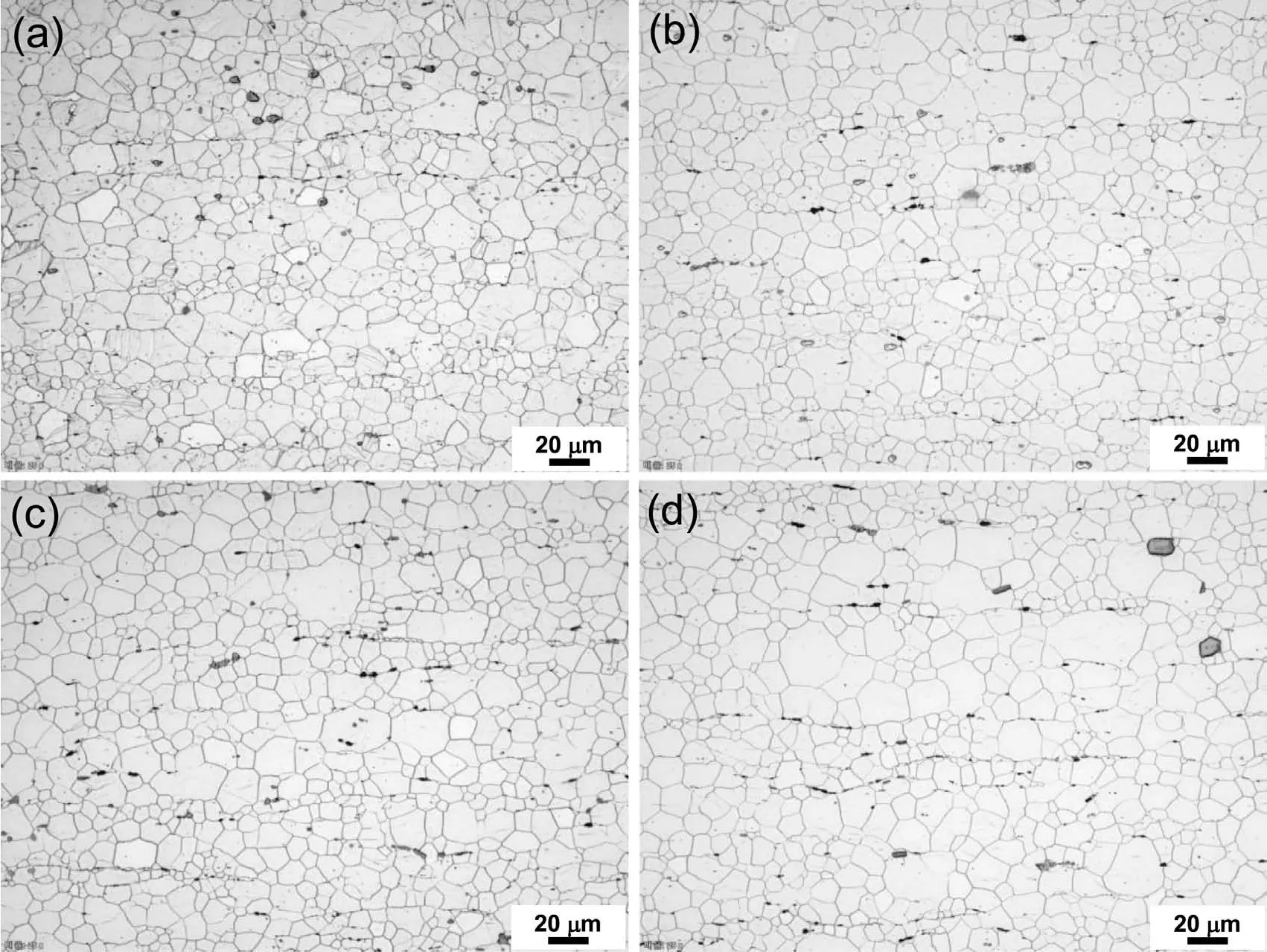
Fig.9.Optical micrographs of HRDSR(a)AZ31,(b)0.01%C-AZ31,(c)0.03%C-AZ31 and(d)0.08%C-AZ31(with a speed ratio of 3)after annealing at 623K for 1h.
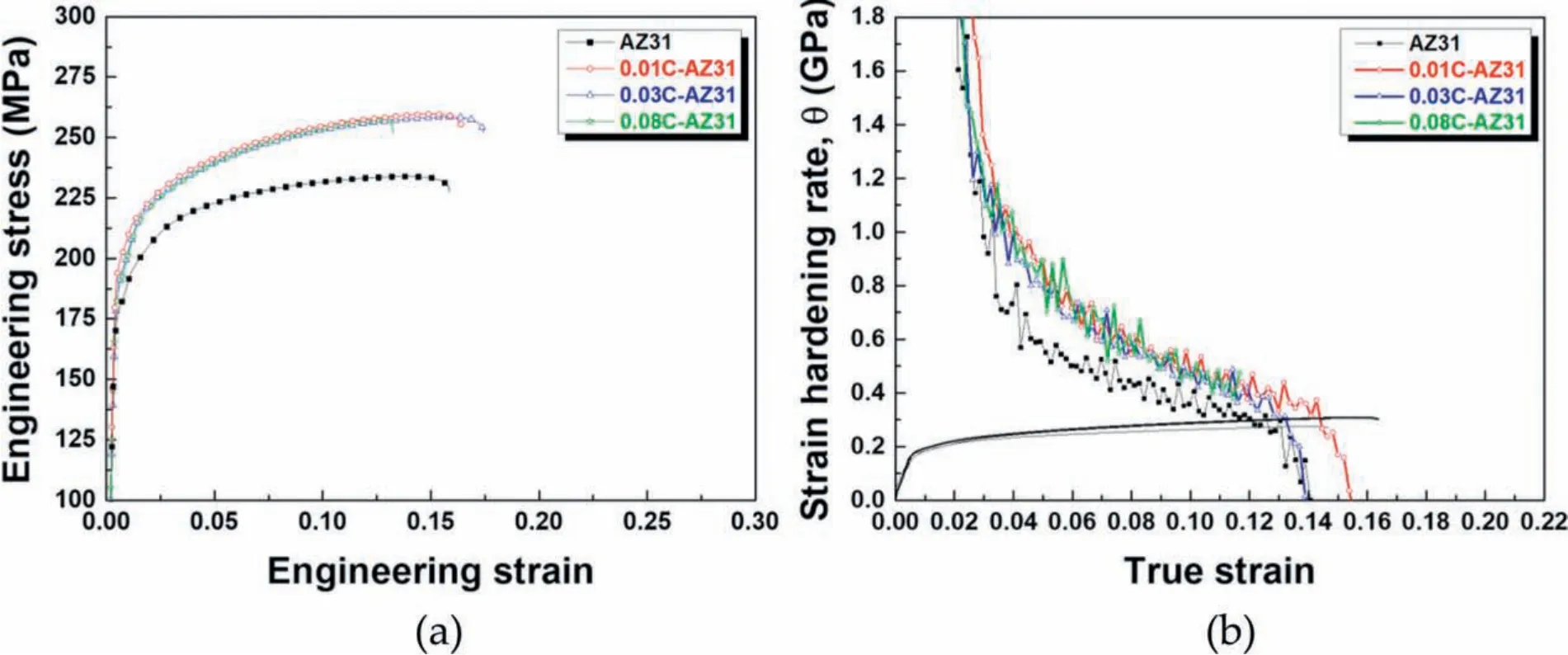
Fig.10.(a)The engineering stress-engineering strain curves obtained from the tensile tests of the extruded samples with different amounts of carbon black.(b)The change in the strain hardening rate and in the true stress as a function of true strain for the four materials.
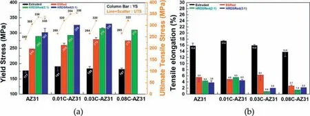
Fig.11.(a)The 0.2% proof yield stress(σy),tensile strength(UTS)and(b)tensile elongation values of the extruded and rolled materials.
The values of yield strength,ultimate tensile strength and tensile elongations of the ESR and HRDSR samples are also plotted in Fig.11(a)and(b).After rolling,the strength was greatly increased,but the tensile elongation considerably decreased due to a largely reduced work hardening ability after heavy plastic deformation.As the speed ratio increased,strength tended to increase,but the tensile elongation decreased.The yield strength and UTS continued to increase as the roll speed ratio increased for a given composition material.The strength tended to increase with increasing amounts of carbon black up to 0.03%.Tensile elongations of the HRDSR samples were,however,poorer compared to those of the ESR samples due to the more significantl reduced strain hardening ability after severe plastic deformation.For example,in the HRDSR samples with 0.03% C,fracture occurred at 0.9%and 2.0% at a speed ratio of 2 and 3,respectively,while fracture occurred at 6.3% in the ESR sample.
Fig.12(a)shows the engineering stress-engineering strain curves obtained from the tensile tests of the annealed HRDSR samples with different amounts of carbon black,and Fig.12(b)shows the change in the strain hardening rate and in the true stress as a function of true strain.The strain hardening rate increased as the amount of carbon black increased up to 0.03%.No further strain hardening occurred at 0.08%C,and fracture occurred prior to necking.The best mechanical properties(σy=172.6MPa,UTS=278.2 MPa,tensile elongation=18.8 % and uniform strain=0.17)were obtained at the carbon-black amount of 0.03%.This carbon amount is larger than that(0.01% C)where the best mechanical properties were obtained from the extruded materials,indicating that HRDSR enhanced the dispersion of the carbon black in the matrix.
4.Discussion
4.1.Strain hardening behavior
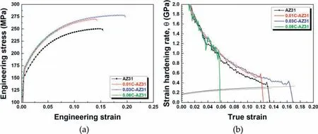
Fig.12.(a)The engineering stress-engineering strain curves from the tensile tests of the annealed HRDSR samples with different amounts of carbon black.(b)The change in the strain hardening rate(θ=dσ/dε)and in the true stress as a function of true strain for the four materials.
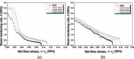
Fig.13.Theθvs.(σ−σy)plots for(a)the extruded materials and(b)the annealed HRDSR materials.
The strain hardening behavior of a material is generally depicted by different stages of Kocks-Mecking plot whereθis plotted as a function of net fl w stress(σ−σy)[9,10].Stage I hardening depends strongly on the orientation of the crystal and does not occur when deformation occur by multiple slip from the beginning of plastic deformation.Stage II hardening is associated with multiple slip and occurs due to the interaction of the dislocations moving on intersecting slip systems.Stage II hardening is related to the geometrical storage of dislocations,and thus considered to be athermal.Stage III hardening is characterized by a hardening rate which decreases linearly with increasing net fl w stress due to dynamic recovery that occurs by large-scale cross slip and climb of dislocations.When stage III approaches to a saturation level,stage IV is possible to appear at large strain.Stage IV is characterized by the low and nearly constant strain hardening rate.
Theθvs.(σ−σy)plots for the extruded materials are shown in Fig.13(a).The extruded materials exhibit the stage II,stage III and stage IV in sequence.A high initialθvalues that form a plateau is normally taken as evidence of a region of linear hardening in stage II.As the amount of carbon black increases,the stage II region becomes more obvious.The composites have the largerθvalues(3400-3600MPa)than the AZ31(2950MPa),indicating that the dislocation storage rate is higher in the presence of carbon black.When dislocations accumulate to a certain extent,θvalue decreases rapidly and linearly,exhibiting the stage III hardening behavior.When the net fl w stress exceeds∼40MPa,stage IV occurs.In stage III,theθvalue increases from 1640 to 3360MPa at(σ−σy)=20MPa with increase in the amount of carbon black.This result agrees with Kumar et al.'s work[11]that showed that the friction-stirred Cu composites containing nonosized ceramic particles displayed the higher strain hardening rate than the friction-stirred base Cu in stage III.The negative slope of the curve in stage III,which is connected to the degree of dynamic recovery,tends to slightly increase as the carbon black amount increases.In stage IV,the strain hardening rates of the composites are almost same,but they are higher than that of the AZ31 alloy.Zhao et al.[12]suggested that progressive conversion of dislocation cells to low-angle grain boundaries with straining is responsible for the occurrence of stage IV in Mg-Zn alloys.As the carbon black is added,the subgrain size is expected to decrease,leading to a higher strain hardening rate in stage IV.
For the case of the annealed HRDSR composites(Fig.13(b)),stage III hardening appeared immediately after yielding,without the presence of stage II hardening.This behavior is very similar to the well-known linear stage III of work hardening in FCC polycrystals[9,13].The initialθvalue increases from 2350 to 2650MPa with increase in the amount of carbon black,but the slopes of the lines are similar,indicating that the influenc of carbon-black amount on dynamic recovery is small.At high net fl w stresses(∼0.09 GPa),the initiation of stage IV is observed in the 0.01C%-AZ31 and 0.03%C-AZ31,but the transition is not obvious compared to that observed in the extruded composites.
Comparison of theθvs.(σ−σy)curves between the extruded materials and annealed HRDSR materials indicates the following results.Although the strain hardening rate of the extruded materials is initially higher,it decreases more rapidly with increasing net fl w stress.As a result,the annealed HRDSR materials maintain higher strain hardening rates than the extruded materials beyond the net fl w stress of∼0.04 GPa.The higher initial strain hardening ability of the extruded materials may be attributed to the weaker basal poles compared to the basal poles of the annealed HRDSR materials,because the orientations favoring basal slip promote the generation and storage of dislocations[14,15].The larger grain sizes of the extruded materials compared to those of the annealed HRDSR materials may not explain the higher initial strain hardening rate of the extruded materials.This is because as the grain size increases,the density of grain boundaries that are geometric obstacles to dislocation motion decreases,leading to a lower accumulation of dislocations at grain boundaries[16-19].The strain hardening rate is determined by a competition between dynamic dislocation generation due to plastic deformation and dynamic dislocation annihilation due to dynamic recovery process[9].The rapid decrease in strain hardening rate of the extruded materials after some plastic deformation,therefore,implies that the high initial dislocation accumulation resulted from increased basal slip is overwhelmed by the accelerated dynamic recovery during straining.The greater degree of dispersion of carbon black in the matrices of the annealed HRDSR materials may more effectively reduce dynamic recovery rate during straining than in the extruded materials.The dynamic recovery rate decreases because the detachment of dislocations from the more well dispersed carbon black is more difficult resulting in increased difficult for dislocations to crossslip from basal onto prismatic planes.
According to the K-M model[9],the strain hardening rate accounting for the recovery effect can be expressed as:

where˙εis the strain rate,T is the absolute temperature,θhis the athermal component of the strain hardening andθrrepresents the softening effect due to the dislocation annihilation by dynamic recovery that is affected by temperature,strain rate and fl w stress.Fig.14(a)shows the plots of(σ−σy)θ vs.(σ−σy)for the extruded materials.When an athermal regime exists,a plot of(σ−σy)θas a function of(σ−σy)should begin as a homogeneous and straight line of gradient ofθhthough the origin.The plot indeed shows the initial hardening behavior that is well described by straight lines.The straight line becomes longer as the amount of carbon black increases.The vertex of the curve corresponds to the starting point of dynamic recovery.An almost plateau region forms after reaching the net fl w stress of about 40-50MPa because stage IV,where(θh−θr(σ,˙ε,T))becomes nearly constant with straining,occurs.Theθhvalue of Mg alloys can be affected by grain size and texture[14,15,17].As the four extruded materials have the similar texture and grain size,the largerθhvalue of the composites compared to that of the AZ31 is most likely attributed to the interaction between carbon black and dislocations during deformation.The plots of(σ−σy)θvs.(σ−σy)for the annealed HRDSR materials shows near parabolic curves that characterize the stage III hardening behavior[16].The initial parts of the curves at low stresses are fitte by straight lines passing through the origin to determine a slope ofθhthat is found to increase with the addition of carbon black.Theθhvalues of the extruded materials are larger by 1.5-1.7 times than those of the annealed HRDSR materials.This result can be attributed to the basal texture effect as discussed earlier.
The Hollomon power-law relation[20]can be applied for describing the strain hardening behavior of the materials:

where k is the strength coefficientεpis the true plastic strain and n is the strain hardening exponent that is a measure of the ability of a material to work harden.
The n value can be obtained from the slopes of the loglog plots of the true stress-the true strain curves.Fig.15(a)and(b)shows the plot of the n values as a function of strain for the extruded materials and the annealed HRDSR materials,respectively.The same n value curves as a function of strain can be obained using the relation of n=(ε/σ)×θ.The strain hardening exponents showed a gradual increase up to a true strain of 0.13 in the extruded materials.The maximum n value for the AZ31 is 0.14,while the maximum n values for the composites are similar as 0.17.For the annealed HRDSR materials,the n value reaches the maximum at smaller strains(∼0.05)compared to the extruded materials.The maximum n values for the AZ31,0.01%C-AZ31,0.03%C-AZ31 and 0.08C%-AZ31 are similar as 0.225,0.23,0.235 and 0.22,respectively,indicating that the maximum n value only slightly increases as result of the addition of carbon black.The n value of the AZ31 alloy,however,decreases more rapidly beyond a strain of 0.05 compared to the n values of the composites.The 0.03%C-AZ31 maintains the largest n values up to a large strain.
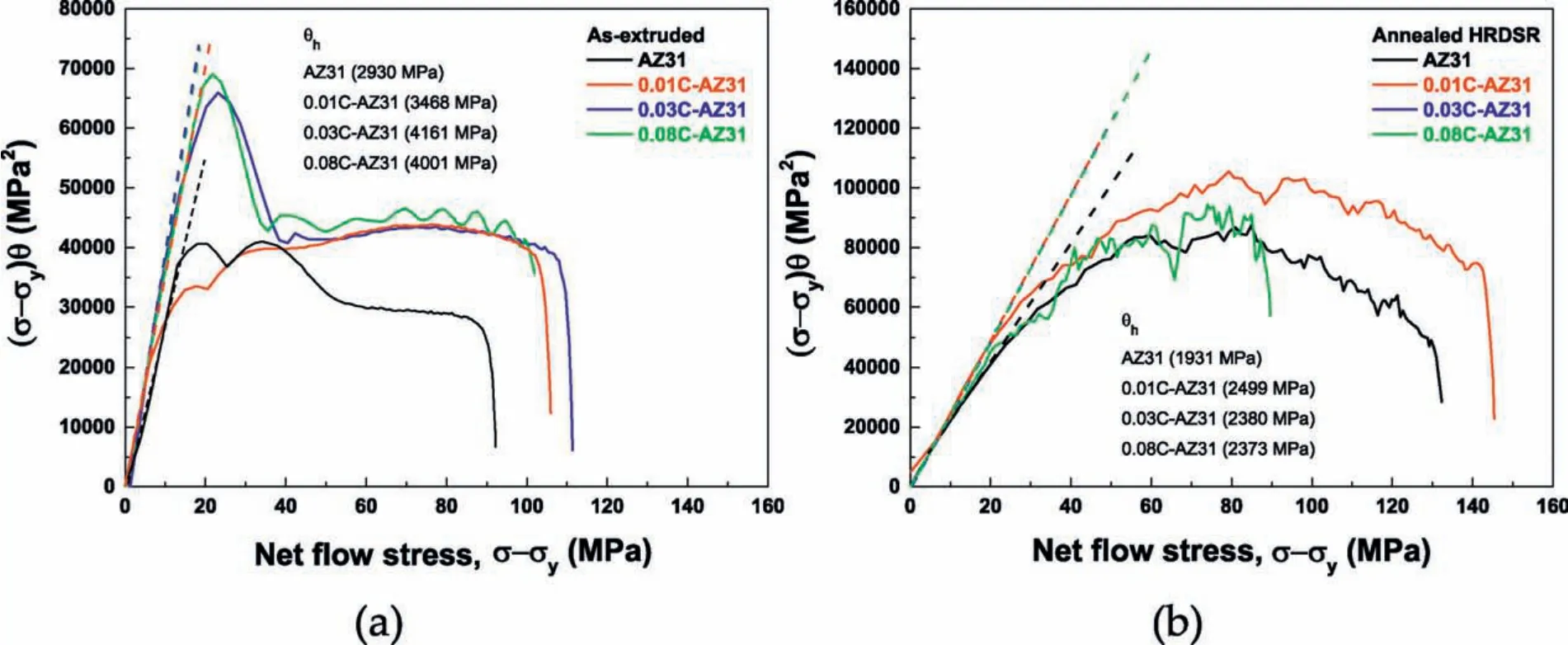
Fig.14.The plots of(σ−σy)θvs.(σ−σy)for(a)the extruded materials and(b)the annealed HRDSR materials.
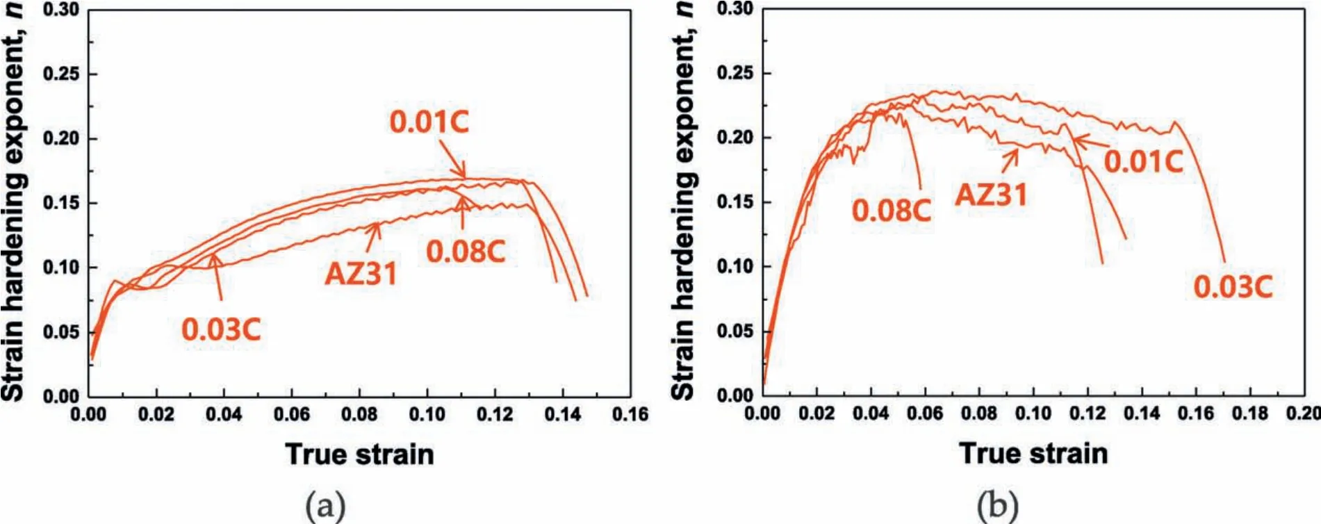
Fig.15.The plots for the n values of(a)the extruded materials and(b)the annealed HRDSR materials measured as a function of true strain.
4.2.Strengthening mechanisms
As the grain sizes of the extruded materials are similar to one another and the grain sizes of the HRDSR materials are similar to one another,the strengthening effect of the composites is considered to primarily originate from the carbon black particles.There are three possible strengthening mechanisms associated with carbon black:(1)dislocation-carbon black interaction by Orowan strengthening,(2)load transfer from matrix to carbon black and(3)dislocation generation due to a difference in thermal expansion between matrix and carbon black.
The increase of yield stress due to Orowan strengthening can be estimated by Eq.(3)[21]:

whereMis the Taylor factor(6.5[22]),Gis the shear modulus of pure Mg(1.66×10⁴MPa[23]),bis the Burgers vector of Mg(3.21×10⁻¹⁰m[23]),ris the radius of nanoparticles,andλis the interparticle spacing,which can be expressed as[24]:

wheredpis the diameter of the particles andVpis the volume fraction of the particles.When it is assumed thatdpis the size of carbon black particle(27nm)and the carbon black is uniformly dispersed in the matrix,the increases in the strength due to the Orowan strengthening mechanism withVp=0.01,0.03 and 0.08vol% are 8.1,14.1 and 23.3MPa,respectively.

The increase of yield stress due to generation of geometrically necessary dislocations caused by thermal stresses originated from the difference in thermal expansion coeffi cient between a matrix and a particle can be expressed by Eq.(5)[25]:whereαis a constant(1.25[25]),ΔT is the temperature change from processing temperature to room temperature(325K)and CMgand CCBare thermal expansion coeffi cients of pure Mg(26×10−6K−1[26])and carbon black(6.6×10⁻⁶K−1[27]),respectively.The increases in the strength due to the thermal mismatch strengthening mechanism with Vp=0.01,0.03 and 0.08vol% are 6.2,10.7 and 17.5MPa,respectively.
The strengthening due to the load transfer from soft matrix to hard carbon black can be estimated by using Eq.(6)[28]:

whereσmis the yield stress of a matrix(177MPa for the extruded AZ31 and 154MPa for the annealed HRDSR AZ31).The increases in the strength due to the load transfer strengthening mechanism with Vp=0.01,0.03 and 0.08vol% are 0.009,0.03 and 0.07 MPa for the extruded materials,respectively,indicating that this strengthening effect is negligible in both of the extruded and annealed HRDSR materials.
The net increase in yield strength due to the three strengthening mechanisms(Δσy)can be coupled together using the quadrature method.In this case,the improvement in yield strength by the addition of carbon black is depictable as follows:

The values ofΔσyare 10.2,17.7 and 29.1MPa at Vp=0.01,0.03 and 0.08vol%,respectively.
The extruded 0.01%C-AZ31 and the annealed HRDSR 0.01%C-AZ31 exhibit a higher yield strength than that of the extruded AZ31 and HRDSR AZ31 by 14 and 13MPa,respectively.This strength increment reasonably well agrees with the prediction by Eq.(7)(10.2MPa),suggesting that 0.01% carbon black could be well dispersed in the matrix using extrusion only.The annealed HRDSR 0.03%CAZ31 exhibits a higher yield strength than that of the annealed HRDSR AZ31 by 18MPa.This strength increment is similar to that predicted by Eq.(7)at Vp=0.03 vol.%(17.7 MPa),indicating that at the amount of 0.03%C,the uniform dispersion of carbon black was achieved under severe plastic deformation by HRDSR.To enhance the dispersion of the carbon black at a higher amount(>0.03%C),a decreased thickness of the carbon black coating layer on the magnesium chips may be advantageous,and for this,magnesium chips with a decreased size compared to that used herein should be applied.
5.Conclusions
Carbon black and magnesium chips were used to fabricate carbon black-reinforced magnesium matrix composites,and the following results were obtained.
1.After extrusion,the magnesium chaps coated with carbon black were well bonded.The addition of carbon black did not significantl affect the grain size after extrusion.
2.After extrusion,the strength,strain hardening rate and tensile elongation increased as the result of the addition of 0.01% carbon black,but a further improvement in the strength and work hardening rate was not achieved with a further increase in the amount of carbon black.The tensile elongation increased due to the addition of 0.01% carbon black but decreased as the amount of carbon black increased.
3.After application of HRDSR to the extruded materials and subsequent annealing,the 0.03% C AZ31 exhibited the best mechanical properties.This occurred because HRDSR improved the dispersion of carbon black using high shear,allowing for an increased amount of carbon black(0.03%)to be more uniformly dispersed in the matrix.
4.The extruded composites exhibited the three hardening stages:stage II,stage III and stage IV,while the annealed HRDSR composites mainly exhibited the stage III hardening.The strain hardening rate increased by the addition of carbon black at all the strain hardening stages.At the initial hardening stage,the strain hardening rates of the extruded composites were higher than those of the annealed HRDSR composites due to the weaker basal texture of the former,but this result became reversed at the later hardening stage due to the more enhanced dispersion of carbon black in the latter.
5.The strength analysis indicates that uniform dispersion of 0.01% and 0.03% carbon black in the matrix is achievable through extrusion and extrusion+HRDSR,respectively,but a uniform dispersion beyond 0.03% amount is difficul even under severe plastic deformation.
Conflic of interest
The paper submitted has no conflic of interest.
Acknowledgments
This research was financiall supported by the Basic Research Laboratory Program through the National Research Foundation of Korea funded by the Ministry of Education,Science and Technology(Project No.NRF2020-000000).
Data availability
The raw/processed data required to reproduce these find ings cannot be shared at this time as the data also forms part of an ongoing study.
杂志排行
Journal of Magnesium and Alloys的其它文章
- The effect of K2SiF6 on the MgH2 hydrogen storage properties
- Influenc of graphene oxide(GO)on microstructure and biodegradation of ZK30-xGO composites prepared by selective laser melting
- The creep behavior of Mg-9Al-1Si-1SiC composite at elevated temperature
- HA coating on Mg alloys for biomedical applications:A review
- Constitutive modeling of f ow behavior and processing maps of Mg-8.1 Gd-4.5Y-0.3Zr alloy
- Fabrication of high-strength duplex nanoporous Cu by dealloying a dual-phase Mg-Cu precursor alloy
