Effect of particles addition to solution of plasma electrolytic oxidation(PEO)on the properties of PEO coatings formed on magnesium and its alloys:A review
2020-12-18ArashFattahalhosseiniRaziehChaharmahaliKazemBabaei
Arash Fattah-alhosseini,Razieh Chaharmahali,Kazem Babaei
Department of Materials Engineering,Bu-Ali Sina University,Hamedan 65178-38695,Iran
Received 4 November 2019;received in revised form 18 April 2020;accepted 4 May 2020 Available online 29 May 2020
Abstract The plasma electrolytic oxidation(PEO)procedure is utilized in order to amend the surface properties of Mg and its alloys.This procedure creates a ceramic coating on the surface applying high-voltage.The presence of deep pores and porosities in the surface that affect the corrosion resistance of the coatings is one of the PEO procedure limitations.One of the useful methods to decrease porosities of coating and improve its fina properties is changing electrolyte conditions based on the presence of micro-and nanoparticles.The present paper reviews the mechanisms of particle adsorption and composition in PEO thin film in addition to the effect of particle addition on the microstructure,composition and corrosion behavior of coatings that were applied on magnesium alloys.© 2020 Published by Elsevier B.V.on behalf of Chongqing University.This is an open access article under the CC BY-NC-ND license.(http://creativecommons.org/licenses/by-nc-nd/4.0/)Peer review under responsibility of Chongqing University
Keywords:Plasma electrolytic oxidation(PEO);Nanoparticles;Microparticles;Corrosion;Magnesium.
1.Introduction
Magnesium(Mg)is the lightest metal among all the engineering metals that has the density of 1.7 g/cm3.Alloys of magnesium have especial benefit while utilizing as structural materials due to their good damping characteristics,high ratio of strength-to-weight,particular rigidity and castability that has made them appropriate in different field in modern engineering[1-6].The major drawback of magnesium and its alloys is that they are really susceptible to corrosion[7,8].It is also one of metals that is among the most electrochemically active ones.Furthermore,the magnesium and its alloys are not highly wear resistant.That is why a wide range of coating methods are developed to dominate these drawbacks for many usages[9-14].Protective coating is a really impressive way in order to enhance magnesium and magnesium alloys corrosion resistance.There are a lot of methods in order to achieve protective coatings including electroplating,sol-gel process[15],chemical vapor deposition[16],and electrodeposition[17,18].Among many possible and accessible coating methods to improve the magnesium alloys corrosion resistance,PEO that is also known as micro-arc oxidation(MAO)procedure,is a popular technique owing to its environmental friendliness and high performance[19-21].
PEO is a plasma chemical and electrochemical procedure.This procedure mixes electrochemical oxidation with a spark treatment having high voltage inside an alkaline solution leading to the formation of a physically protective oxide fil on the metal surface in order to increase corrosion and wear resistance in addition to long lifetime of components[22-25].This process can make really hard-kind of like as hard as corundum-tenacious and dense coatings on surface of magnesium and its alloys[8,26-31].It is noticeable that the PEO process is a multifactor-controlled procedure that is affected by numerous factors whether intrinsic or extrinsic ones[32,33].The substrate materials compositions and electrolyte are considered to be intrinsic factors that play a major role to the structure and PEO coatings composition whereas the extrinsic factors are normally composed of processing temperature,oxidation time,electrical parameters as well as additives[34-38].The effective parameters on the PEO coating properties are shown in Fig.1.
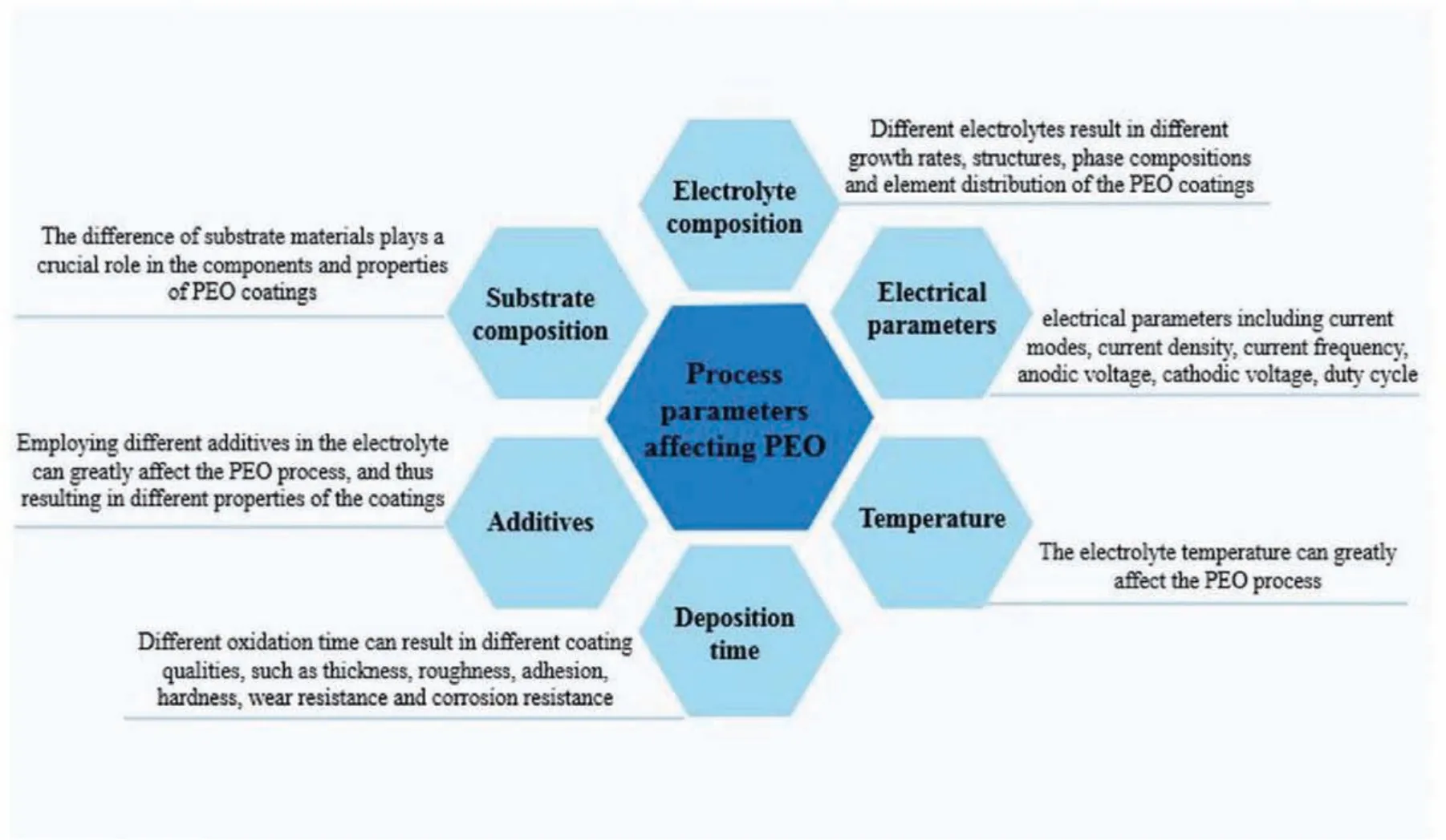
Fig.1.The effective parameters on the PEO coating properties.
PEO coatings create a two-layered morphology that has an amorphous outer fil with a porous and coarse morphology in addition to an inner and crystalline f lm having many fin pores[39-42].The cavities are as a result of the oxygen production that may be joined to the crystallization of amorphous elements in the inner fil[43].Nevertheless,it is improbable to prevent high porosity of PEO coatings,specifi cally for magnesium alloys and behaviors of coatings are also limited because of the restricted effect of the electrical parameters on the composition of coating.Another helpful method to optimize the composition and microstructure for amending the improve properties of coating is to modify composition of the electrolyte[44].The latest advancements in this fiel have focused on adding particles into the solution,aiming at in-situ incorporation or the porous PEO coatings sealing and making the coatings have new functionalities.Adding particles into the solution affects the PEO procedure.This happens because it can alter the solution,i.e.conductivity,pH and viscosity that may affect morphology and properties of the coating as a result[34,40].
When particles are combined with no formation of a new phase or without a reaction,it is noticed as an unmoving incorporation.It means the shape and size of the particles are not noticeably changed.The other possibility is an incorporation which is reactive or a little reactive.In this condition,the particles may be melted as a result of the high-energy discharges in the process of PEO and have a reaction with other elements of matrix and electrolyte.This complicated procedure depends on many parameters including the substrate,Zeta potential(ζ)and particles concentration,melting point,electrolyte composition and the energy that is provided via the discharges[45-47].This review gives a general and critical review about the effect of dissimilar particles on the PEO procedure,composition of coating and corrosion behaviors of magnesium and its alloys.
2.The effect of utilized particles in PEO coatings
In many studies,addition of particles to the solution are in the powder forms or sol.Since it has more fl xibility and provides more options than the particles diminishing over the substrate.Furthermore,formation of in-situ particle may happen inside the electrolyte deliberately or if the solubility extent of some compounds is surpassed throughout PEO procedure[48].Also,such methods can be noticed as electrolytes of particle-containing.Obtaining uniform particles dispersion in the electrolyte of PEO is a challenge.A significan factor that explains the behavior of charging at the interface of the solid-liquid isζ.This method is used to calculate the filζin terms of the equation of Helmholtz-Smoluchowski[49,50].Theζmagnitude shows the degree of electrostatic repulsion among the adjacent particles within the electrolyte.Particles having higher value ofζare more stable and this leads to avoid agglomeration and settling in electrolyte of PEO.A highζis favorable in electrophoretic procedure as this increases the particle movement rate under a certain electrical fiel[51,52].
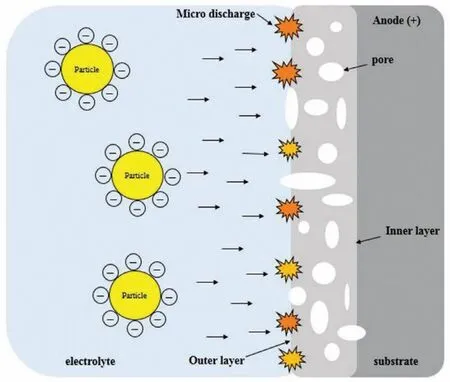
Fig.2.Schematic illustration indicating the particles addition to the oxide fil within PEO coating.
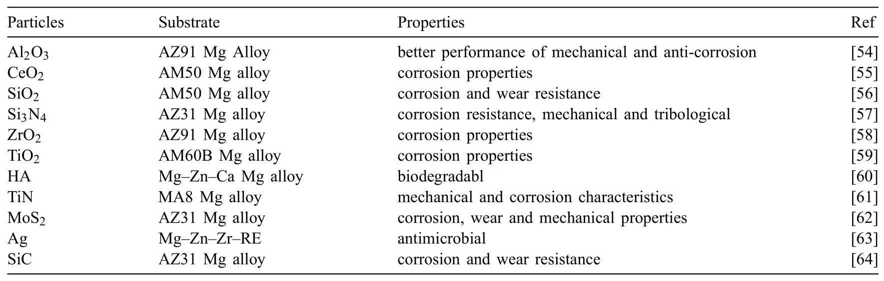
Table 1Particles applied in PEO processing
Fig.2 illustrates the adding particles to the oxide fil within PEO coating.It was discovered many of these particles are negatively charged and show a negativeζin the current and utilized alkaline solutions.The negativeζcan simplify the particles incorporation as the substrate and the coating on its surface act as anode within positive or DC pulses under conditions of AC[53].Table 1 gives an outline of different particles which have been used in the PEO solution intending to achieve improved properties and presenting new functionalities of PEO coatings[54,55,64,56-63].
3.Absorption of particles and mechanisms of incorporation in the electrolytes
The absorption and incorporation of particles mechanisms of in PEO coatings have been investigated in a many studies recently.Pores on the surface of coating were noticed as uptake paths of particles to go into the coating as the pores are generally fille by the particles after PEO process.Bordbar-Khiabani et al.[65]studied that the morphological changes that were observed and according to the electrochemical theories,the subsequent mechanism is suggested for ZnO nanoparticles incorporation into the coating of MgO.ZnO nanoparticles are not able to be dissolved in aqueous solutions like ionic types.They are also negatively charged after they are distributed within the solution.Thus,it is supposed that the surface of the ZnO nanoparticles which are negatively charged makes them migrate toward the substrate of AZ91 acting as the anode of positively charged(Fig.3(a)and(b))[65].While starting the oxidation procedure,at the frst step,a thin and protective f lm is formed on the substrate right away within the alkaline electrolyte and the zinc oxide nanoparticles will be trapped in this fil(Fig.3(c))[65].
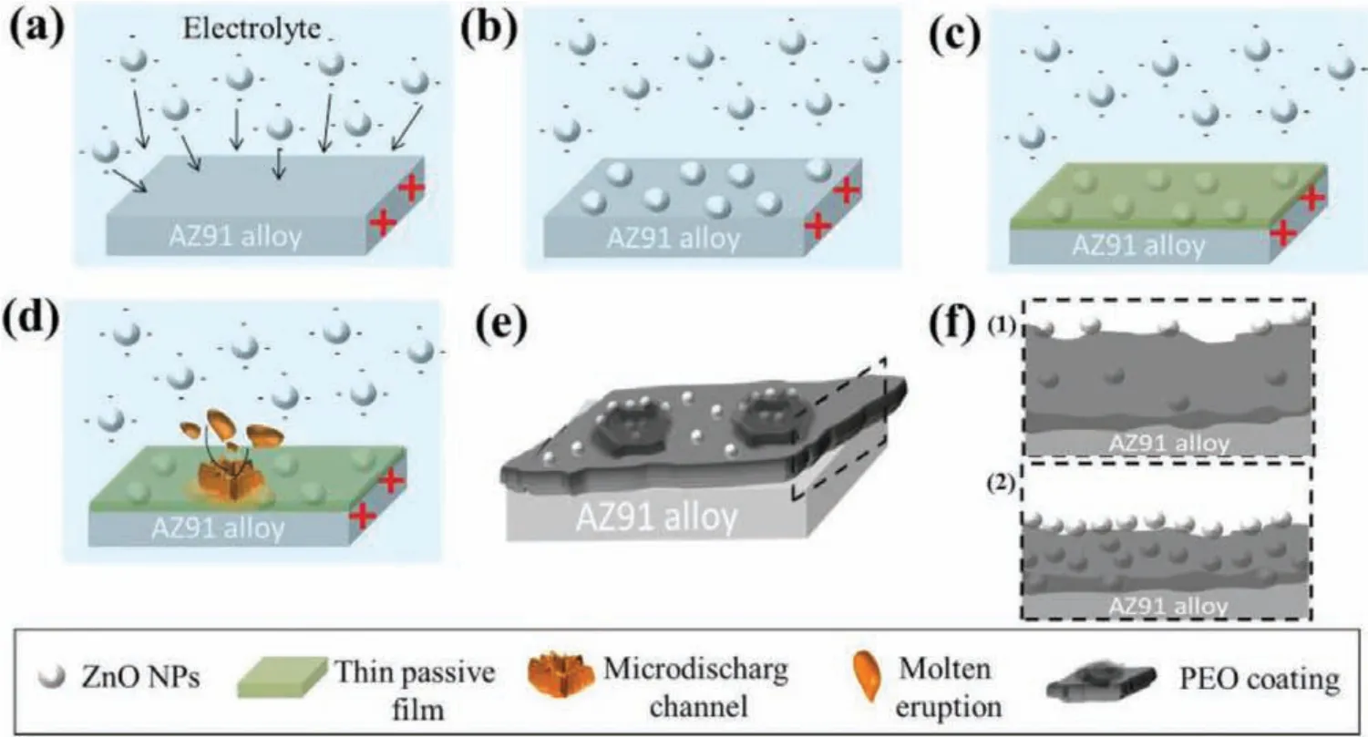
Fig.3.Mechanism of coating growth on AZ91 alloy:(a)negatively charged zinc oxide nanoparticles attracted to the surface,(b)deposition of nanoparticles,(c)formation of thin protective layer,(d)formation of micro-discharging channel and molten eruption,(e)formation of PEO coating,and(f)schematic of PEO coating(cross-sectional view)at low and high concentration of nanoparticles[65].(With permission from Ref.[65];License Number:4695501203007,2019,Elsevier).
Arrabal et al.reported that during anodizing period,thin passive layers having the thickness of∼300 and∼200 nm were created on magnesium,respectively[66].Then after dielectric breakdown and the sparking onset,zinc oxide nanoparticles are yet being adsorbed via the oxide film especially via the discharge channels having higher energy of surface,under the effect of the electrophoretic force.The molten oxide eruption leads a section of the accumulated zinc oxide nanoparticles to be trapped in affinit of the discharge channel throughout micro-discharge(Fig.3(d)and(e))[65].Moreover,fluctuatio and perturbation of the molten oxide while sparking result in incorporation of a few ZnO nanoparticles in the electrolyte near electrical discharge site and quick solidifi cation because of the contact with the electrolyte causing their incorporation into the oxide fil(Fig.3(e))[65].Repeating micro-discharges beside each other shifts and dislodges the combined particles.The zinc oxide nanoparticles might be detached from the molten oxide within perturbation during any of these stages.Rising ZnO nanoparticles concentrations inside the electrolyte make more particles be trapped in the coating in all of the above stages.However,the thickness of the oxide fil will be reduced by declining energy arising from micro-discharge.So,rising the concentration of ZnO nanoparticles result in the oxidation f lm higher density,but this will reduce its rate of growth(Fig.3(f))[65].In conclusion,ZnO nanoparticles incorporation inside the oxide coating within PEO procedure arises from their physical uptake over the substrate because of their mechanical intermixing with the molten oxide within the perturbation that were made using micro-discharges as well as the electrophoretic force.
All of the related studies obviously show that particles incorporation can happen either by reactive,relatively reactive or inert incorporation within PEO procedure,relying on the composition of electrolyte,employed electrical factors,substrate,melting point,size and the particles chemical stability[67].It is noticed to be an inert incorporation,if particles are mixed with no reaction or no new formation of phases.The other probability is reactive or relatively reactive incorporation when the particles are melted via high energy of discharges and then the reaction with other parts from the matrix and electrolyte.
In addition,the particles melting point sounds to play a significan role in the incorporation mode.Particles having a high melting point,for instance,CeO2(2400 °C),SiC(2730 °C),Si3N4(1900 °C)were mostly incorporated inertly,disregarding their sizes.Particles having kind of lower melting points were reactively incorporated[68].Also,the particles size affects the incorporation mode of particle,the coating properties and PEO procedure by extension.For example,ZrO2particles with nano-size(150-300 nm)have depicted a reaction with kinds of magnesium to produce Mg2Zr5O12in the outer fil of coating even if they have high melting points[53].
The size influenc of adding particles on PEO coatings has been studied,there are still many questions,though.Particularly,the absorption and incorporation manner of particles having distinct melting points and sizes is still to be established.Also,adding particles intrinsic mechanism to the PEO coating is still vague and obscure.For example,Arrabal and coauthors[69]claimed that zirconium dioxide nanoparticles addition into the PEO coating were moved to the interface of the outer/inner fil via short-circuit routes in the outer film Oppositely,Lee and coauthors[53]indicated that the mechanical combining and electrophoretic mobility within oxide of molten magnesium were major parameters resulting in incorporation of particles.Table 2 depicted kind of the particles,the substrate information,composition of electrolyte,coatings phase composition and incorporation manner of the particles[70,71,80,72-79].
Furthermore,the applied electrical factors play a significan role to specify the incorporation form of particles too,because the lifetime and intensity of the discharges are promptly as-sociated with the current density and voltage throughout the PEO procedure.The particles properties(size and melting point)and the applied electrical factors within PEO procedure directs the manner of the particles absorption and incorporation into the film Lu et al.[81]reported that in addition to the most current electrical factors(current density and voltage),duty ratio and frequency affect the absorption of particles within PEO treatment.Lower frequency and higher duty ratio let more particles incorporate into the PEO coating.Table 3 demonstrates the effect of operation conditions on PEO coating biodegradability[82-86].
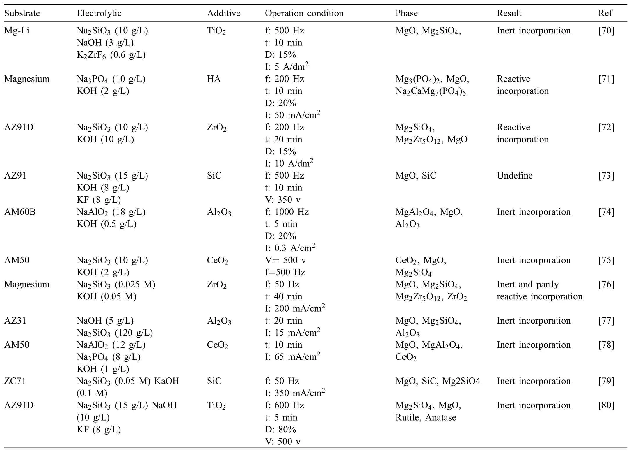
Table 2Detailed information of the substrate,electrolyte,type of the particles,operation condition,phase composition of the coatings and incorporation mode of the particles
4.Particle addition effect on electrical parameter and electrical response of PEO procedure
In general,voltage or current control is utilized for PEO process.Consequently,the current decreases or voltage rises proportionally depending on the procedure time since the dielectric ceramic fil insulating property is constantly boosted.As alkaline solutions are frequently utilized,particles got negatively charged and moved to the anode(magnesium alloy)accompanied with anions under the used electrical potential.As a result,the particles can be incorporated in PEO procedure and coating treatment.Adding particles into the electrolyte normally affect the PEO procedure.This is ascribed to the change in the composition and the electrolyte conductivity that plays a significan role in the PEO procedure[87].
According to Fig.4[64],it is clear that the particles addition affects the PEO procedure e.g.the voltage and current evolution within the procedure.In the case of f xed current system,the voltage rises more rapidly after the potential of breakdown and attains higher values by adding particles.The current declines earlier and quicker in the presence of particles during the mode of constant voltage.
Wang et al.[88]reported that the responses of voltage−time in the PEO procedure with nano-SiC and without it are illustrated in Fig.5.As is shown,the responses of voltage−time in the PEO procedure accompanied the same tendency with and without nano-SiC within the solution.But,nano-SiC addition to the electrolyte reduced the voltage increasing rate.It was discovered that the PEO procedure can be distributed to three steps based on the voltage increasing rate[89].In the primary step-in a high slope and the voltage increasing rate-(stage I),voltage augmented extremely withtime with nanoparticles and without them in the electrolyte is approximately similar.It can be noticed at the start of the experiment,the electrode was energized,and due to the deposition that occurs on the anode,a thin dielectric layer was formed on the surface immediately.As a result,the sample resistance augmented and thus the voltage augmented quickly.This procedure called anodic oxidation.Within this stage,the electrolyte did not have any reactions with the substrate,therefore,the nanoparticles addition into the electrolyte did not affect any changes in voltage.In step II,the voltage still augmented with time.Moreover,the voltage increasing rate with nanoparticles within the electrolyte was less than that of without nanoparticles within the solution.Reaching the striking voltage,the PEO process started(stage III).
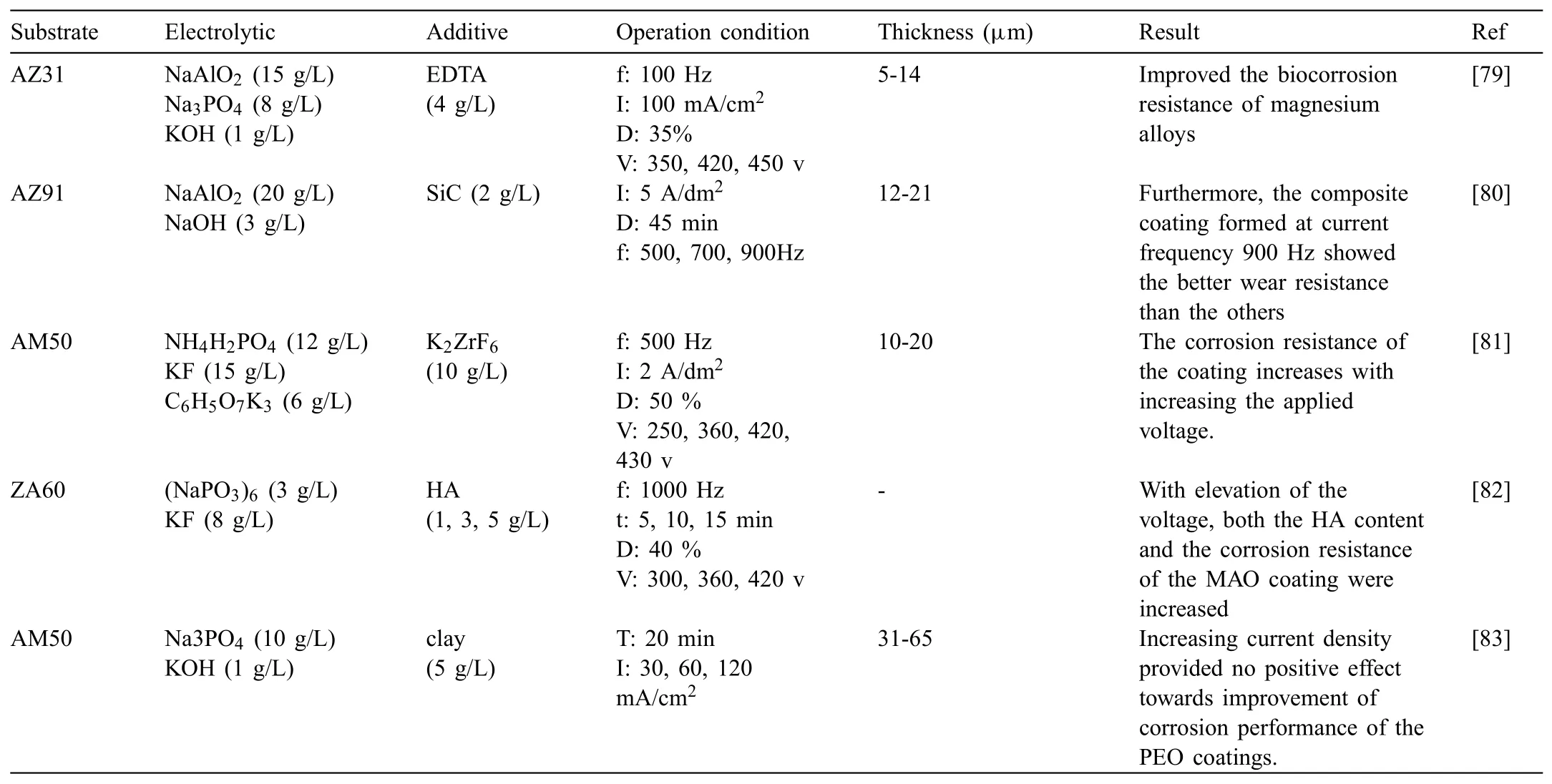
Table 3Effect of operation conditions on PEO coating with addition of nanoparticles to the electrolyte.
The PEO coating growth is a procedure having multiple cycles: formation of layer→breakdown→melting→sintering→layer formation again.In addition,due to fairly big nanoparticles surface energy,they are able to absorb negative ions of the solution in order to make particles of negatively charged colloidal.By the electric fiel effect,these colloidal particles moved to the anode(alloy of magnesium)and collected on its surface so,prevented alloy of magnesium discharge breakdown procedure and as a result reducing the growth rate of layer.In the last step(stage III),the voltage augmented more gradually while comparing to the previous two steps.Li et al.[90]proved that the addition of TiO2nanoparticles into the electrolyte caused the voltage to increase more quickly.But,debatable results of the voltage response and fina voltage were realized by other scholars[91-93].
5.Particle addition effect on morphology and microstructure of the coating
It is obvious that the morphology and microstructure of the coatings that were loaded by particles are distinct compared with the coatings of particle-free as the introduced particles affect PEO procedure and take part in the formation of coating.Diverse oxide particles have been utilized in order to modify PEO coatings applied on magnesium and its alloys.Generally,oxide particles that have small sizes and low melting points can have reactive incorporations much more easily than particles with high melting points that are large-sized.Small-sized particles(SiO2nanoparticles)have been melted,reacting with other constituents and leading to amorphous phase higher fraction in the coatings.In return,the coatings composition that was obtained in solutions having micro-sized particles of SiO2was not considerably influence except for the existence of inertly incorporated particles[64,94].
Lu et al.[64]indicated that micro and nano-sized particles of SiO2were in-situ incorporated into coatings of phosphatebased(These coatings are named as PPEO)and these particles effect on the composition,microstructure and coatings behaviors was studied.Fig.6(a,b and c)exhibit the differences of the surface morphology for the PEO coatings with and without addition of particles[64].PPEO(n-SiO2)has many pores but their sizes are smaller than those of the other two coatings and many pores are not totally filled There is no difference between PPEO and PPEO(μ-SiO2),except for many small adhering particles on the later coating surface.Adding particles of micro-sized into the electrolyte does not alter the roughness of coating considerably.The morphology and microstructure of PEO coatings are affected by introduction of particles,e.g.,the fil compactness and pore characteristic.Adding oxide particles into the solutions can decrease the number and/or size of the pores on the surface of coating[58,64,72,95].But,it was demonstrated that the surface of coating was not affected a lot[77,96]or got more porous while adding oxide particles into the electrolytes[54].
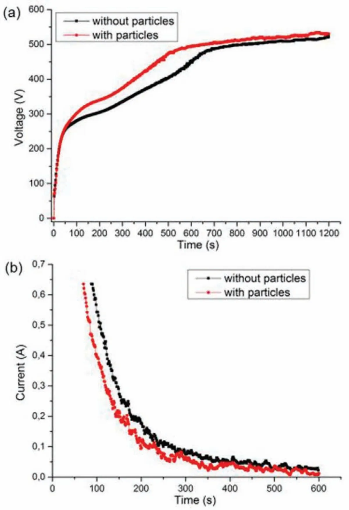
Fig.4.(a)Voltage evolution under current control and(b)current evolution under voltage control during PEO treatment in solutions with and without particles[64].(With permission from Ref.[64];License Number:4695500446514,2019,Elsevier).

Fig.5.Voltage vs.time during the PEO treatment[88].(With permission from Ref.[88];License Number:4696910147115,2019,Elsevier).
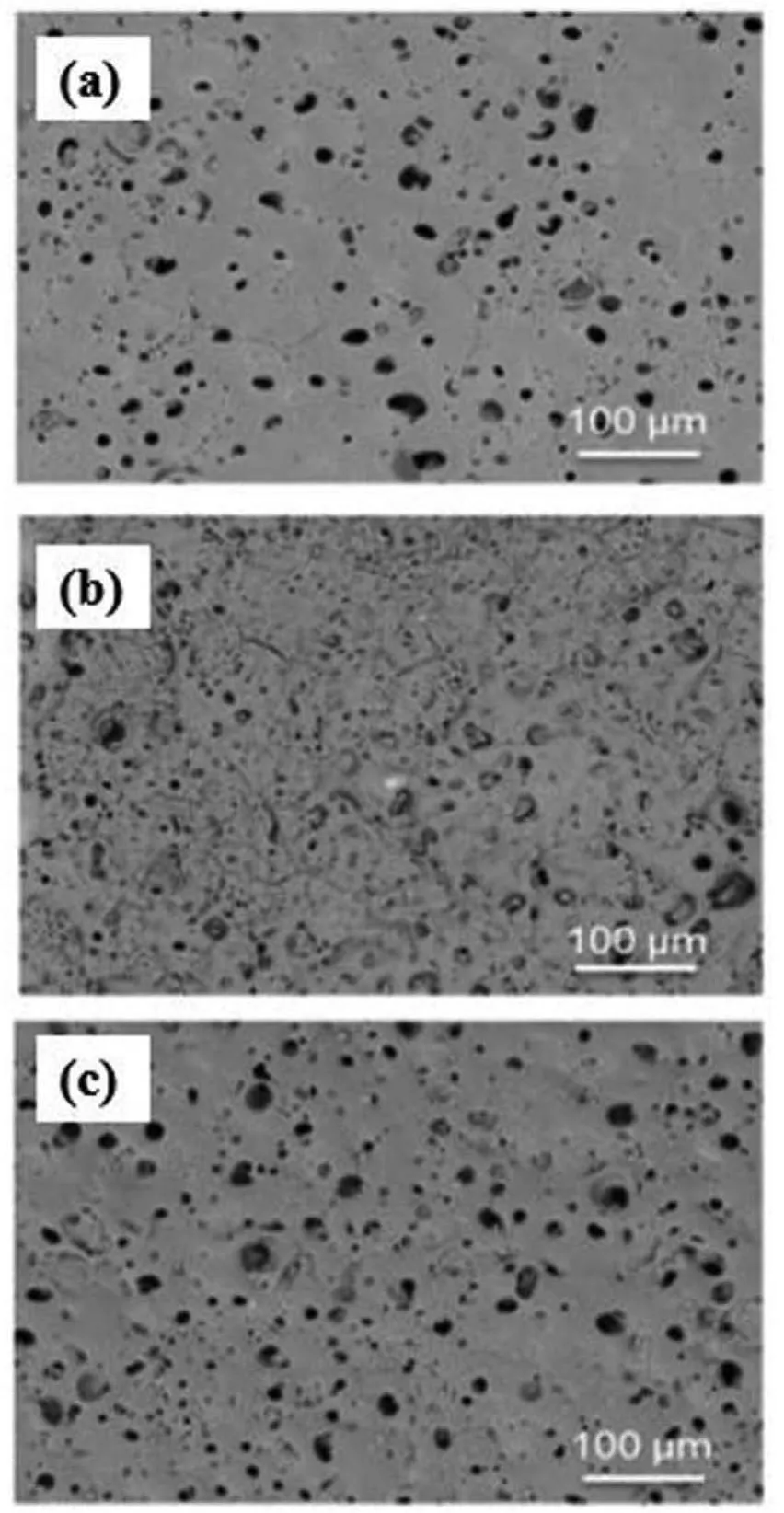
Fig.6.Surface morphology of the PEO coatings(a)PPEO,(b)(n-SiO2)PPEO,(c)(μ-SiO2)PPEO[64].(With permission from Ref.[64];License Number:4695500446514,2019,Elsevier).
Liang et al.[58]reports that Oxide layers have been formed on AM60B alloy of magnesium by PEO procedure in an electrolyte of alkaline phosphate by adding titanium dioxide(titania)sol and without it.Fig.7(a)and(b)show the surface morphologies of the oxide layers that were formed inside solution without titania sol and with it,respectively[58].Normal morphology of a formed oxide layer within electrolyte of alkaline phosphate with no addition of titanium dioxide sol is shown in Fig.7(a).It is obviously seen that the oxide layer on outer surface divulges a fairly rough surface.Cracks and micropores are discovered to be on top of the surface.The micropores diameter varies from 1 to 10μm.Obviously,these bigger micropores possess an open structure which deeply goes into the layer.It is accepted that it will not penetrate to the whole oxide layer[97].The surfaces of specimens(Fig.7(b))are coated by layers that are more steady in comparison to that of Fig.7(a)by adding titanium dioxide sol into the alkaline phosphate solution.Moreover,the formed oxide layer inside this solution has fewer and smaller micropores in comparison to that was formed within the electrolyte of alkaline phosphate.Also,it is observed that these micropores are revealed in order to be internally blocked.Thus,the titania sol addition to alkaline phosphate solution can create a considerable change in the morphology of surface,making a uniform oxide layer having less structural imperfections in the magnesium alloy structure.Lim and coauthors[94]created PEO layers on AZ31 inside a Na2SiO3-based solution having CeO2nanoparticles.Nanoparticles of CeO2were totally contributed to the coating and fille cracks and pores throughout the surface.
Madhankumarat at el.[98]investigated the effect of adding Ta2O5nanoparticles(1,5 and 10 g/L)on properties of magnesium alloy of AZ31.As it is observed in Fig.8[98]particles were totally participated in procedure of f lm formation and ideally fille up the available cracks and pores.Metallic and non-oxide particles such as organic(Polytetrafluoroet ylene(PTFE))and inorganic(Si3N4and hydroxyapatite),are normally inertly contributed into the PEO f lms[85,99,100].Unmoving incorporated particles are mostly known to decline the porosities of PEO coatings.For instance,the pores on the surface of coating were more homogenous and tinier after PTFE particles incorporation.
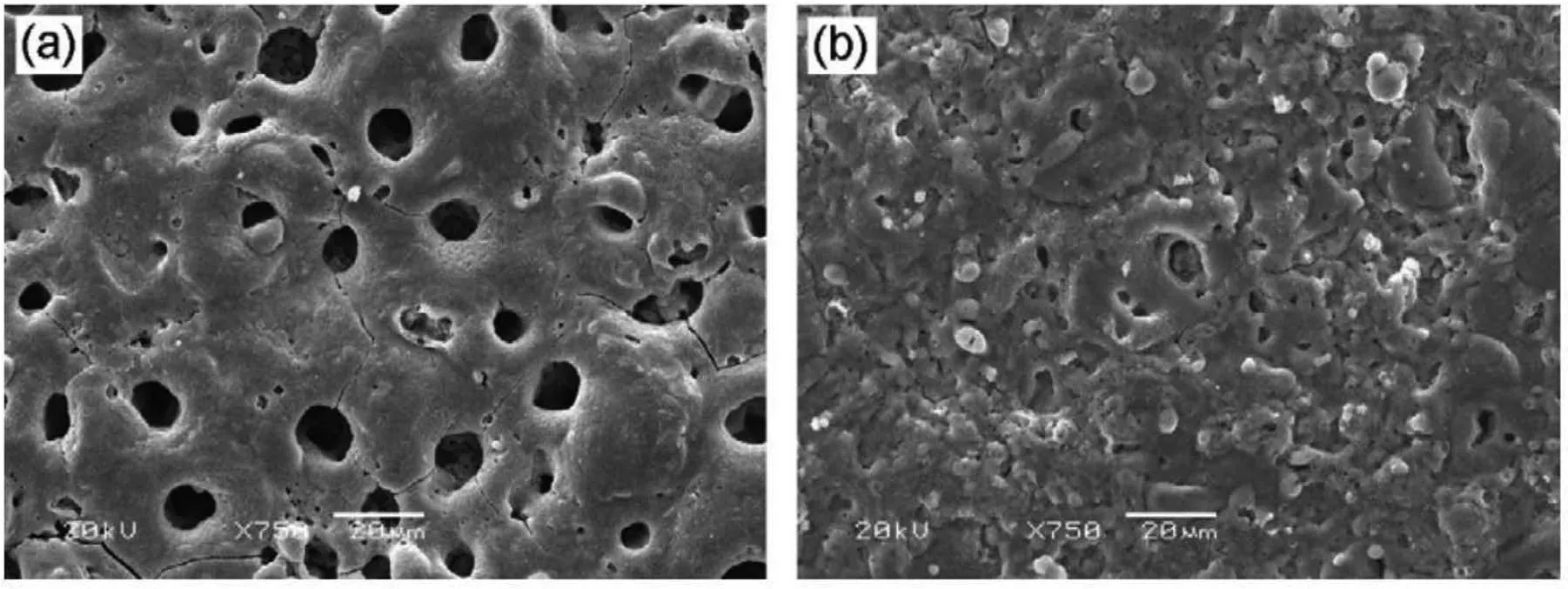
Fig.7.SEM micrographs of oxide layer formed in a phosphate solution(a)without and(b)with addition of 4% titanium dioxide sol[58].(With permission from Ref.[58];License Number:4695500724604,2019,Elsevier).
Blawert at el.[101]investigated the clay particles that were taken up as appropriate additives due to their possible reactions with the products of substrate-electrolyte conversion and their fairly low melting points.Comparing formed coatings in electrolytes with particles and without them obviously presents a whole change in the microstructure.However,all of the surfaces are controlled by the existence of cracks and pores throughout the coating.A combination of open and a little fille pores are observable on the surface using the standard electrolytes.They are produced by the PEO procedure discharges.The observable thing is the discharge channel surface side end attaining down across the coating to the substrate.The size is most probably dependent on the energy in the discharge and the composition of coating(melting point)specifying the melted coating using the discharge.Bigger pores and higher volume of melt often leads to closed or relatively closed pores while cooling the larger volume of melt is slower and the melt is able to fl w back before solidification closing or relatively closing the discharge channel after the discharge finished They are hard sticking on the surface showing that the absorption of the particles occurs mostly over the surface.Low energy and small discharges might not melt all of the phases or the volume of melt is little and cooling is fast.So,the discharge channels are not able to be closed by the melt of liquid before solidificatio creating open pores.If a specifie energy and size is attained by the discharges,the distinct phases and constituents of the coating begins to melt and particularly the clay additions are responsible to rise the volume of melt by reducing the melting point.Therefore,the pool of melt around the discharge gets bigger and cooling is lower and gives rising the time for the melt to f ow back in the channel of discharge before solidification The consequence is a bigger diameter of pore in addition to the development of fille pores[101].
6.Particle addition effect on the thickness of coating
In terms of cross-section morphology,all of the produced coatings can be distributed into three distinct zones including pore band,outer fil and inner compact barrier film Based on the mechanism of growth that was reported[102],PEO coatings grow to the reverse directions concurrently,containing inwards growth to the substrate and outwards growth to the interface of coating/solution.The inwards growth can be ascribed to the oxygen diffusion towards the magnesium,whereas the outwards growth in thickness arises from the persistent ejection of molten material on the surface of coating and its following solidification Finally,the band of pore is created because the two directions growth dynamics are not always similar,leading to an unfille zone in the coating.The outer fil is really thicker in comparison to the two other parts of the coating,absorbing more than half thickness of whole coating.Nevertheless,a lot of observable imperfections can be seen unexpectedly in a fairly low magnification Generally,these imperfections are trapped gas pores,residual discharge channels and open pores that are produced because of the spontaneous solidificatio and short-lived sparks that are made by the immediate cooling by the solution.So,it is supposable that this outer fil is not able to supply adequate protection of substrate versus corrosion.Oppositely,the inner fil has a thickness of just about 2μm,but some imperfections can be divulged in the f lm and at the boundary of substrate/coating.Thus,it can be realized that the formed coatings are cohesively f xed to the substrate and resistive to corrosion mostly because of the fairly compact inner fil protection[102].
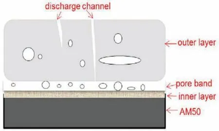
Fig.9.Schematic representation of the cross-section[68].(With permission from Ref.[68];License Number:4695510273025,2019,Elsevier).
Yang at el.[71]reports that the defects existed in the outer layer tend to be sealed by adding and rising the HA particles concentration.This optimization in morphology of cross-section is in a good agreement with corresponding microstructure of surface that offers the particles of HAp could influenc the discharge behavior and alter the composition of coating[64].
Lu at el.[68]a simple model structure of the cross-section can be offered(Fig.9)[68]assisting the later and more analysis.Nevertheless,these three zones volume ratios will change among the distinct systems.The coating having the highest thickness possesses the outer fil with highest thickness.Pores with small sizes sound to be gas inclusions that were trapped within solidificatio after micro-sparks vanished.Some discharge channels are observable for any coatings and the pores which are open are also present on the surface and are not totally penetrating.The thickness and compactness of the f lm can be changed or increased in the existence of oxide particles.It was found that the coating outer fil got more compact and steady in comparison to the formed coatings in electrolytes of particle-free[75,77].
There is no obvious tendency for the effect of particles on the thickness of coating.It was realized that oxide particles were not efficien to enhance the thickness of coating as the coatings normally indicated the same thickness[53]or even got thinner[64,77]by adding particles.However,several reports explained that the coatings were a little thicker[54,76]in the existence of particles.Changing the thickness of the particle-containing coatings is related to the changed evolution of voltage/current within PEO procedure.
Lu and co-workers[103]proposed that the nanoparticles addition changes the evolution of voltage and current within the PEO reaction to make an alteration in the thickness of coating.The alternation depends on nature of added nanoparticle and can make either an enhancement or a reduction in the thickness of coating.Particularly,a tendency of declining thickness was reported as Si3N4nanoparticles were added into the reaction of PEO on AM50[83],while thickness of coating enhanced when nanoparticles of Al2O3were added to a PEO treatment on AZ91D,probably because of the reaction between the magnesium substrate and Al2O3particles[54].It seems that increasing in the thickness of the PEO coatings for AM50 is due to the formation of Mg2SiO4phase because of the reaction between molten MgO and Si3N4nanoparticles within the plasma discharge[83].
Lee et al.[50]considered adding nanoparticles of titania and zirconia that have the sizes of∼200 nm to phosphate solutions.Increasing the voltage was seen at different solutions that was related to the enhancement in electrical resistance of layers due to titania and zirconia addition.Like any other formed PEO layers in phosphate solutions,cross-section analysis divulged a coating formation with outer and inner film[104].ZrO2particles could be seen really obviously in SEM studies.Nevertheless,particles of titanium dioxide were not discovered that is because of not higher melting point of titania in comparison to zirconia.As a result,it is protected to suppose that plasma temperature on the surface of specimen was between melting point of zirconium oxides and titanium.
Wang at el.[54]reports that the oxide fil having Al2O3nano-additive was so thicker than those with no Al2O3,and as a result the coatings average thickness enhanced by the Al2O3nano-additive concentration(Fig.10)[54].This result shows that the suspended particles of Al2O3result in the change in the formation as well as the fina coatings thickness.While adding into the electrolyte,the nanoparticles of Al2O3that attained the surface of coating and penetrated to the pores and then melted in addition to the partially reaction with molten MgO in MgAl2O4in discharge channels.
7.Particles addition effect on coatings corrosion behaviors
The two Tafel branches intersection clarifie the corrosion procedure as shown in Fig.11.The corrosion potential(Ecorr)is associated with thermodynamic aspect,showing the corrosion susceptibility,while the corrosion current density(icorr)clarifie the corrosion average rate through the area of sampled surface.In general,a lowericorrand a higherEcorrnormally show a higher corrosion resistance and also a better anti-corrosion function.The curves of cathodic polarization show the hydrogen evolution via reduction of water,whereas,the curves of anodic polarization indicate the magnesium matrix dissolution.The presence of coating can remarkably affect the cathodic and anodic reaction.It must be noticed that polarization plots do not surely provide an actual picture of the corrosion resistance owing to effect of the negative difference.Thus,theicorrabove was define by the current density at the vertical intersection via theEcorrwith slope of the cathodic Tafel.The measured values are fairly qualitative and mostly show the coating barrier properties and are not presenting any information about the kinetics of electrochemical charge transfer that is one normally expects about Tafel method[105].The current of cathodic polarization for all coatings is clearly less than that of magnesium substrate,showing that the cathodic hydrogen evolution is limited by the coating.Increased corrosion behaviors are mostly due to recently formed and stable phases or via the inertly incorporated particles that have a really high chemical stability[53,58,77].
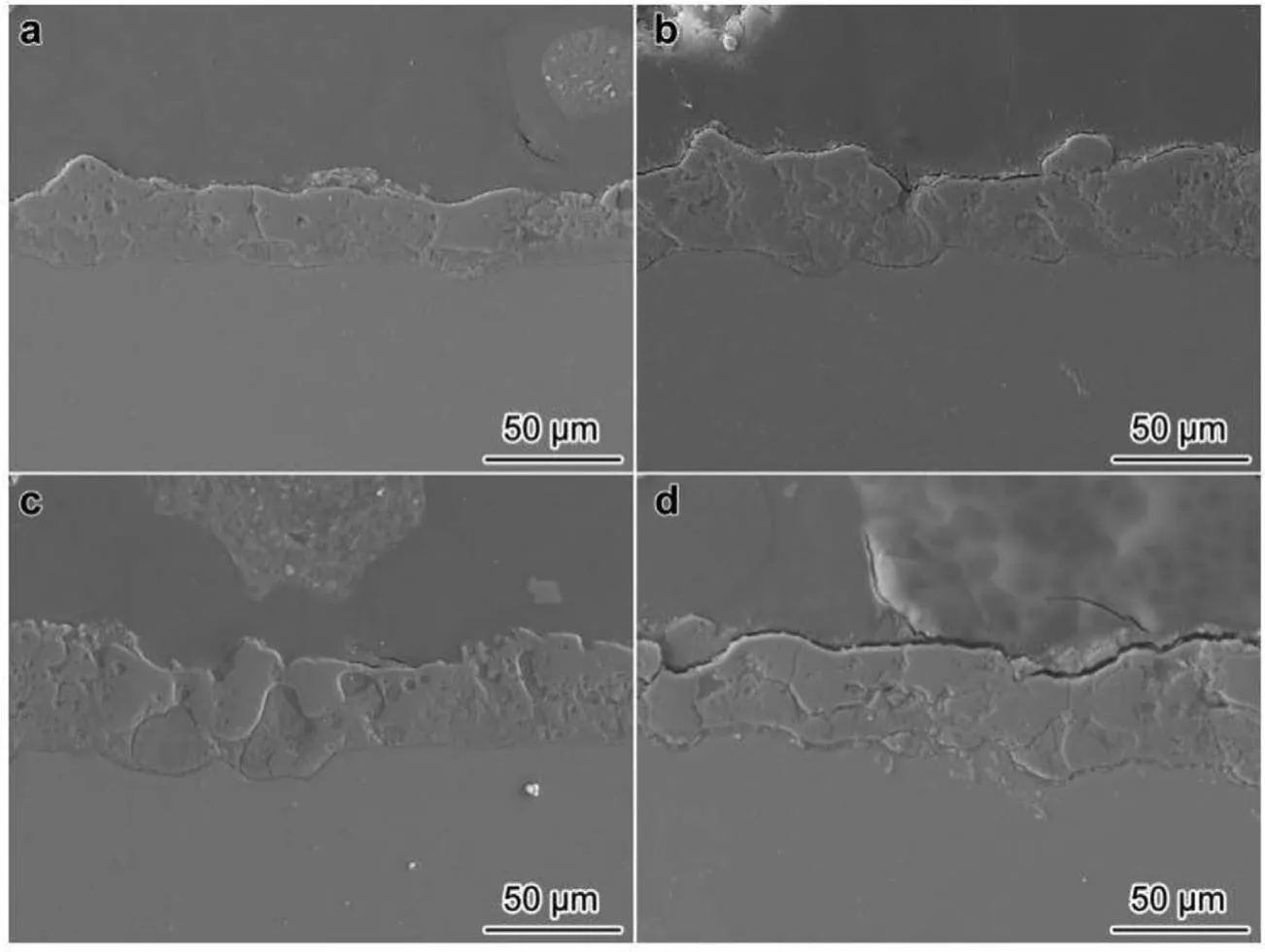
Fig.10.Cross-sectional micrographs of PEO coatings prepared on AZ91D with different concentrations of Al2O3 nanoparticles in solution:(a)0,(b)5,(c)10 and(d)15 g/L[54].(With permission from Ref.[54];License Number:4695520385622,2019,Elsevier).
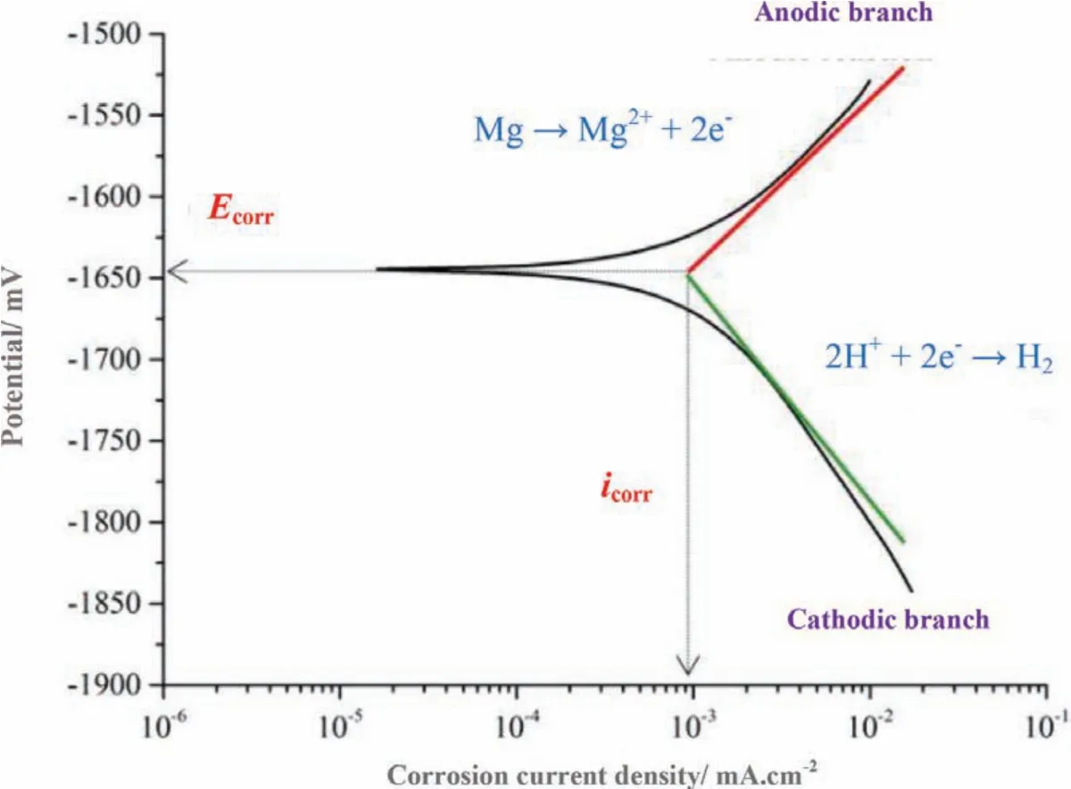
Fig.11.Schematic description of the determination of corrosion current density(The two Tafel branches intersection clarifie the corrosion procedure).
Seyfoori at el.[106]demonstrated that nanocomposite layer has higher corrosion resistance in comparison to the pure PEO coating.The curves of potentiodynamic polarization for the pure PEO,bare alloy and the nanocomposite layers in r-SBF environment are illustrated in Fig.12[106].The corrosion test parameters likeicorr,Ecorrand polarization resistance(RP)of the samples have been analyzed using Tafel extrapolation at the linear step of the cathodic and anodic curves.It is obviously observed that theicorris declined around one magnitude order through incorporating the nanoparticles in the oxide layer.Moreover,nanocomposite coating demonstrates greaterRPthat enhances more or less two orders of magnitude in comparison to the bare alloy of magnesium and pure PEO layer.Existence of the nanoparticles in the PEO structure has been taken from the layer that can block the corrosive environment diffusion having Cl ions,towards the substrate and as a result,they can enhance the nanocomposite coating corrosion resistance in comparison to pure PEO coating.This occurrence involving the structural pores that fil the layers of micro-arc oxidized can be owing to HAp nanoparticles large ratio of surface to volume.
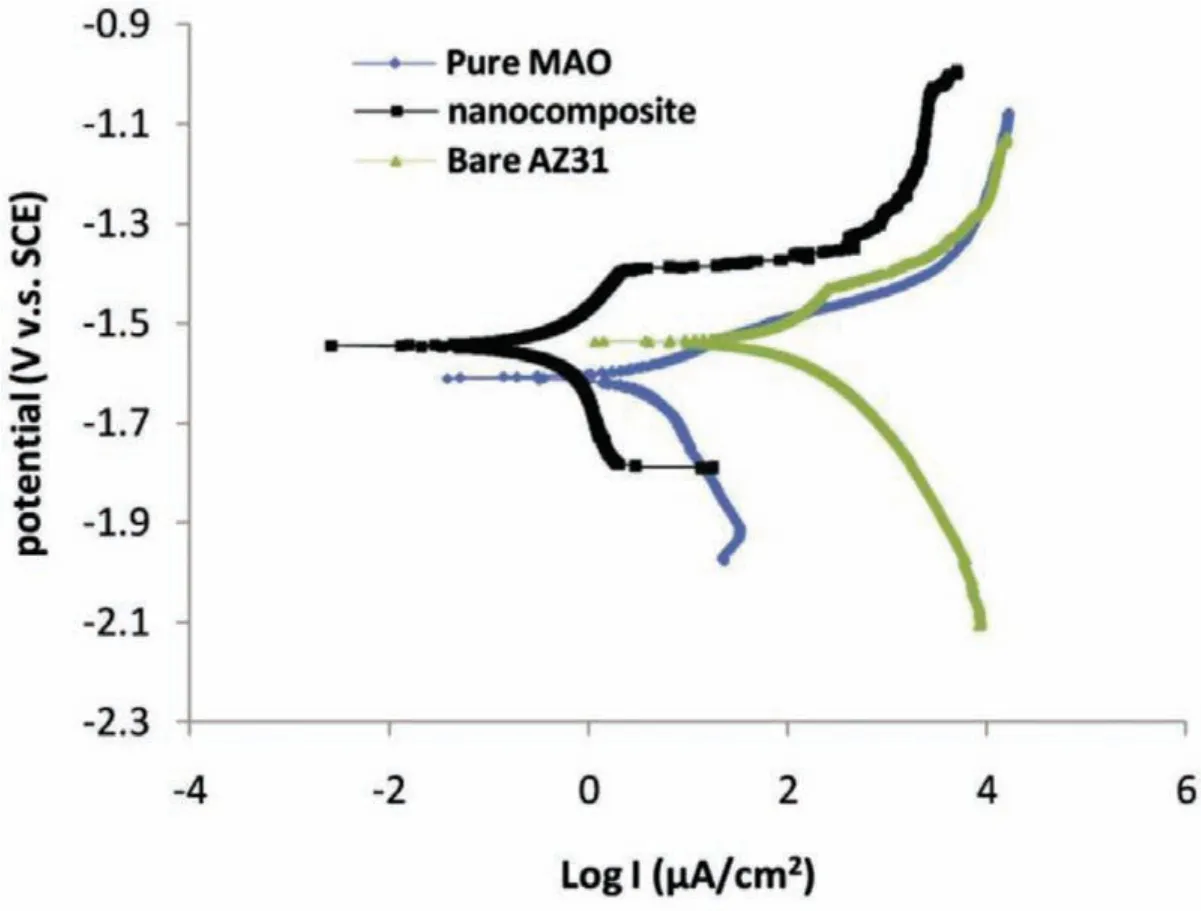
Fig.12.Polarization plots of the experimental specimens in r-SBF solution[106].(With permission from Ref.[106];License Number:4695520110185,2019,Elsevier).
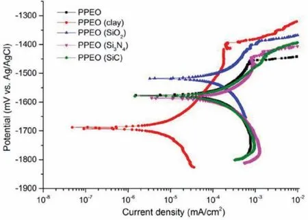
Fig.13.Polarization curves of the coatings[107].(With permission from Ref.[107];License Number:4695511439038,2019,Elsevier).
Lu at el.[107]investigated effect of particles having distinct melting points on PEO coatings properties.PEO coatings were formed on AM50 in an electrolyte of alkaline phosphatebased with addition of SiO2,clay,Si3Ni4and SiC micro-sized particles and without their addition.They indicated that clay particles reactive incorporation helps to formation of a dense fil and therefore amends the coating corrosion resistance.The PEO coatings corrosion resistance was measured using potentiodynamic polarization(Fig.13)[107].It is obvious that the coatingicorr(8.7±2.2 nA.cm−2)loaded using particles of clay are much less than that of other coatings.Notice that polarization test just gives restricted data and reflect the fil short-term corrosion resistance and so,long-term electrochemical impedance spectroscopy(EIS)measurements have been carried out in order to specify the corrosion resistance of PEO coatings.EIS was applied in order to determine the degradation procedure and corrosion behavior.The coatings show a double-loop pattern in Nyquist plot that occurs simultaneously well with their relative curves of Bode plot in medium and low frequencies.Taking a closer look to the Bode plots indicates that there are specifie signs of a third relaxation procedure in high frequencies.This high-frequency time constant could be ascribed to the existence of the outer PEO film whereas the one at medium frequencies demonstrate the response from inner barrier film Eventually,the procedure of low-frequency relaxation can be related to the electrochemical activity(capacitance of double layer and resistance of charge transfer)in the imperfections at interface of metal/solution.

Fig.14.(a)Nyquist and(b)Bode plots of samples coated with various concentrations of HA[108].
Chaharmahali et al.[108]studied the effect of adding HA nanoparticles(5,10 and 15 g/L)on properties of AZ31 magnesium alloy.Fig.14(a)illustrates the Nyquist plots of the EIS tests for coated specimens of HA NPs at different concentrations[108].The Nyquist diagram displays that the uncoated sample has inductive treatment,as magnesium alloys are produced as faced the atmosphere,a porous oxide fil is produced on them and as immersing in a corrosive electrolyte,the oxide fil of the corrosive solution goes through them and attains the substrate,making an induction behavior because of their low corrosion resistance.The Nyquist diagram indicates that the formed coatings at various concentrations of HA have the similar behavior.The coatings have two capacitive loops and an inductive treatment that the existence of these three loops present the existence of three procedures.The produced loop at high frequencies is connected with the outer porous fil and exhibits the inner dense f lm at medium frequencies and also divulges the corrosion procedure at low frequencies with an inductive treatment.The inductive treatment shows that pitting corrosion has happened in the specimens.Increasing the percentage of HA NPs from 5 to 15 g/L,the Nyquist loop diameter rises that displays that the coatings corrosion resistance has been increased[108].
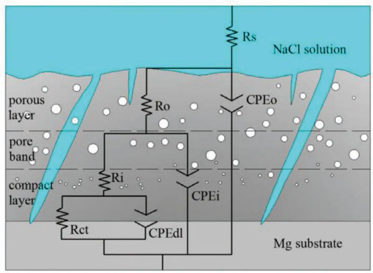
Fig.15.The best electrical equivalent circuit used for modeling the experimental impedance data of PEO coatings formed on Mg Alloys[71].(With permission from Ref.[71];License Number:4783721293516,2020,Elsevier).
Fig.14(b)displays Bode curves of the EIS tests for coated specimens of HA NPs at different concentrations[108].So,the curve at high frequencies has linear treatment in which the impedance value shows the strength of solution.A steep slope was made by the capacitive treatment happening in the circuit at median frequencies.There is a new slope in the curve after linearizing at low frequencies that is less steep than the slope at intermediate frequencies.This slope is due to the inductive treatment at low frequencies that proves the Nyquist curve behavior.According to the Bode curve in the low range of frequency,the impedance amount displays the corrosion resistance owing to the existence of a higher percentage of nanoparticles f lling the cavities,declining the porosity and so reducing the defects.Therefore,the HA 15 specimen has the most impedance and the best corrosion treatment[108].
Yang et al.[71]supplied equivalent circuit to simulate the corrosion behavior of PEO coatings as shown in Fig.15.In the suggested circuit,Rsshows electrolyte resistance between reference electrode and working electrode.Two sequential groups of resistor paralleled combination(RoandRi)and constant phase element(CPEoand CPEi)are used to depict the capacitance and resistance of the outer porous fil and inner barrier film respectively.Rctand CPEdlshow the resistance of charge transfer and double f lm capacitor at the interface of substrate/coating,whileR0and CPEohint at the resistive and capacitive response from the outer porous fil[71].
Bordbar-Khiabani at el.[65]studied the concentration of 0 to 4.5 g/L zinc oxide nanoparticles effect in electrolyte of phosphate-based on the corrosion behavior of coatings.Fig.16(a)-(c)reveals the EIS plots of PEO coated specimens[65].The symbols stand for the experimental data and the solid lines stand for f tting data.The corrosion behavior of the specimens can be qualitatively compared with the EIS plot.In this conditions,bigger semicircles normally show a higher corrosion resistance[109].Specimen Z3 indicated the capacitive loop with greater radius,showing it supplied a better and effective corrosion protection in comparison to other specimens.Moreover,the impedance module(|Z|)of Specimen Z0 was in the range of 64 kΩcm2in little frequencies,while the impedance of Specimen Z3 was 8 MΩcm2at the similar frequencies(Fig.16(b)).According to Fig.16(c),the PEO coatings having the ZnO nanoparticles show an enhancement in the phase angle peak in high frequency that is an ordinary characteristic for the coating system impedance.Moreover,for specimen Z3 the phase angle is about 80° proposing that the electrochemical procedure happening in a high frequency and declines the rate of corrosion[65].
Mohedano et al.[77]studied the effect of CeO2particle concentration on the coatings fina microstructure within the solution and its affection on the corrosion behavior.CeO2particles were included into the coatings and situated preferentially in cracks and pores.The process affects both rising and reactive absorption of CeO2under local melting that was made via micro-discharges.Fewer concentrations of CeO2within the solution results in an incomplete block of the cracks and pores in the coating.Nevertheless,an increment in the concentration of particles up to 10 g/L produces more heterogeneous microstructure having higher number of cracks and pores that are unsealed.The short term corrosion behavior of the coated specimens was specifie via the microstructure of the coatings;thus PEO-CeO2-3 g/LL divulged the highest amounts of the entire resistance and PEO-CeO2-10 g/LL depicted the lowest comparing with PEO coating without addition of CeO2.
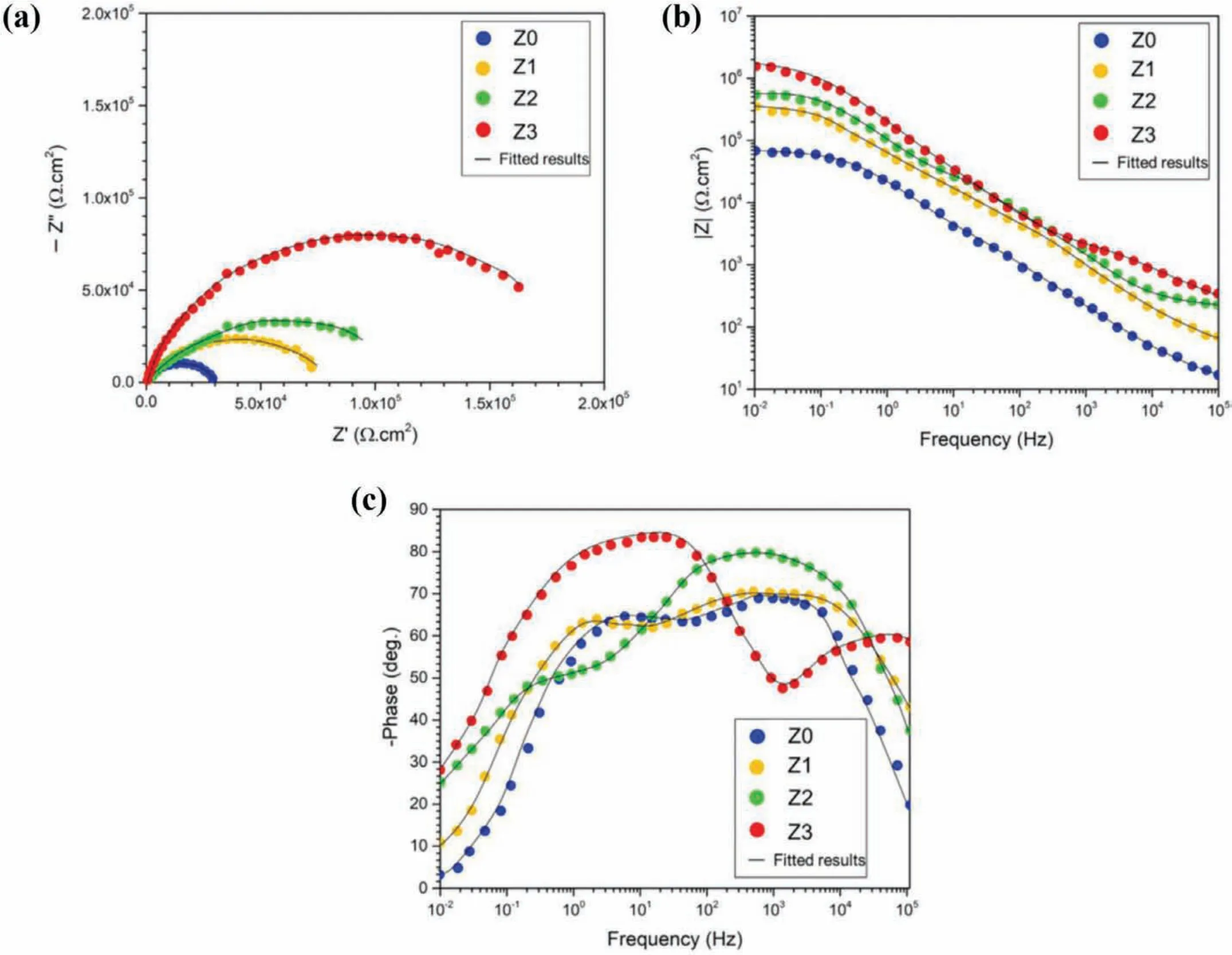
Fig.16.(a)Nyquist and(b,c)Bode plots of the coated specimens[65].(With permission from Ref.[65];License Number:4695501203007,2019,Elsevier).

Table 4Influenc of particle addition on corrosion properties

Fig.17.EIS spectra of the uncoated AZ31 alloy sample and the four PEO-coated samples:(a)Nyquist plots and(b,c)Bode plots[110].(With permission from Ref.[110];License Number:4777710185118,2020,Elsevier).
Li et al.[90]studied the effect of TiO2nanoparticles addition(2,4 and 6 g/L)on properties of AZ91 magnesium alloy.As adding TiO2nanoparticles in the solution was lower than 4 g/L,it helped to make more uniform and thicker coatings having smaller micropores than that was produced in the solution without nanoparticles of TiO2.Nevertheless,abundant TiO2can make a concentrated thermal effect that can decline the corrosion resistance of the coating because of forming cracks,as discovered with addition of the TiO2nanoparticle 6 g/L.
Zhao et al.[110]studied the effect of GO nanoparticles addition(0,1,2 and 3 g/L)on corrosion properties.The EIS(Nyquist and Bode)spectra of the coated and uncoated AZ31 alloy specimens are indicated in Fig.17[110].Comparing with the E0 specimen,the other three specimens with GO in their PEO coatings indicated greater capacitive loops,with the E2 sample showing the biggest loop.The pronounced increment in the magnitude of the impedance showed an important enhancement in corrosion resistance upon the PEO process.Electrochemical investigates the PEO coatings disclosed that the corrosion resistance of the PEO coatings was enhanced upon the GO incorporation in the structures of coating.So,the PEO coating produced the presence of 2 g/L GO during the PEO procedure indicated the best uniformity of coating,the highest corrosion resistance and the highest carbon content.Higher GO concentrations in the solution made an increment in many micropores and a decline in the uniformity of the coating structures leading to a decline in the corrosion resistance.With respect to the corrosion behavior,distinct particles(CeO2,TiO2and ZrO2)have been used to amend the corrosion behavior of PEO coatings on magnesium and magnesium alloys(Table 4[111-118])but controversial consequences have been discovered.
8.Conclusion
An effective method for surface modificatio and optimizing morphology,microstructure,chemical composition and corrosion properties of PEO coatings is introducing particles.One of the beneficia techniques for decreasing porosities of the coating and amend its fina properties is to alter conditions of electrolyte based on the presence of particles.The uniform particles dispersion in the electrolyte of coating procedure seems like a challenge.Zeta potential is utilized in order to evaluate the charge level of particles and dispersion stability.Most of the nanoparticles have negative zeta potential in the common alkaline electrolytes which are typically used in the PEO procedure.As the substrate and the produced coating on it are utilized as anode,the negative zeta potential can promote the particles incorporation into the coating.The structure of coating surface is modifie by particles incorporation and sealing the present pores.As a result,this improved microstructure declines the penetration of destructive ions from the coating to the substrate that leads to an increase in corrosion resistance of the PEO coatings.The particle adsorption procedure is carried out at high temperature and pressure of discharge and nature of the particle can specify the state of particle incorporation by itself.Particles can incorporate the coating in inert or reactive mode.The way particles incorporate(inert or reactive)depends on the used electrical parameters,the electrolyte chemical composition and the properties of the particles like size,melting point and chemical stability.Particles with a lower melting point or smaller size can more easily experience reactive incorporation into the coating.Particles having low melting point can incorporate the coating inertly while having high chemical stability.Inert incorporation occurs when particles incorporate the coating without reaction and the formation of a new phase.Under these conditions,there is no large change in particle size and shape and the particles are easily known in the coating and only surface reactions between the particles and the coating surface may occur.The reactive incorporation occurs when the particles are melted by high-energy discharges and then they are again reacted with components of substrate and electrolyte.
Declaration of Competing Interest
The authors declare that they have no known competing financia interests or personal relationships that could have appeared to influenc the work reported in this paper.
杂志排行

Journal of Magnesium and Alloys的其它文章
- Microstructure and tensile properties of magnesium nanocomposites fabricated using magnesium chips and carbon black
- The effect of K2SiF6 on the MgH2 hydrogen storage properties
- Influenc of graphene oxide(GO)on microstructure and biodegradation of ZK30-xGO composites prepared by selective laser melting
- The creep behavior of Mg-9Al-1Si-1SiC composite at elevated temperature
- HA coating on Mg alloys for biomedical applications:A review
- Constitutive modeling of f ow behavior and processing maps of Mg-8.1 Gd-4.5Y-0.3Zr alloy