Constructal design method dealing with stiffened plates and symmetry boundaries
2020-11-04RodrigoAmrlGrgoriTroinCristinoFrgssAnPvloviMreloCunhLuizRohElizldodosSntosLirioIsoldi
Rodrigo R. Amrl, Grégori S. Troin, Cristino Frgss*, An Pvlovi Mrelo L. Cunh,Luiz A.O. Roh, Elizldo D. dos Sntos, Liério A. Isoldi
a School of Engineering, Federal University of Rio Grande, Rio Grande, Brazil
b Advanced Applications in Mechanical Engineering and Materials Technology, University of Bologna, Bologna, Italy
c Departament of Mechanical Engineering, University of Vale do Rio dos Sinos, São Leopoldo, Brazil
Keywords: Deflection minimization Stress minimization Optimal design Plates with stiffeners Bending
ABSTRACT A new computational procedure for modelling the structural behavior of stiffened plates with symmetry boundary conditions is here presented. It uses two-dimensional finite elements as a way to decrease computational time without losing precision thanks to a relatively small number of elements applied for analyzing out-of-plane displacements (deflections) and stresses. Adding, the constructal design method was included in the procedure, together with the exhaustive search technique, with the scope to optimize the stress/strain status of stiffened plates by design changes.For the purpose, a reference plate without stiffeners was initially design and used as starting point.Part of the volume was reshaped into stiffeners: thickness was reduced maintaining unchanged weight, length and width. The main goal was to minimize strains and stresses by geometric changes. Results demonstrated that, thanks to this design procedure, it is always possible to find an adequate geometry transformation from reference plate into stiffeners, allowing significant improvements in mechanical behavior.
Plates are thin-walled structures that result from the engineering tendency to find a compromise between the high structural load-carrying capacity and low structural weight [1].Whereas the thin-wallness does a great job in achieving this objective, it also makes the structures more susceptible and sensitive to dynamic loads, buckling, etc. Various engineering solutions have been developed to address this aspect. Some of those imply the use of rather modern materials such as fiber-reinforced composite materials [2, 3] to produce directionally dependent properties, or even the so-called "smart" materials to produce active structural behavior [4]. Those solutions involve significant expenses. On the other hand, one of the most frequently used classical solutions characterized by high robustness, cost-effectiveness and relative simplicity is the application of stiffeners.
Plates with stiffeners may have a higher strength with a relatively lower amount of material than plates which contain no reinforcement, making them an economical structure because it presents an improvement in the resistance and rigidity in relation to its weight. These structural components mainly use steel as a material for its fabrication due to their high resistance in the different states of stresses. They can be used in architectural engineering, for example, in reinforced concrete slabs with unidirectional or bidirectional beams, often used on the floor of buildings. In civil engineering, decks of road bridges generally consist of stiffened plates with rectangular, triangular, or trapezoidal ribs. Also, the use of stiffened plates is indispensable in naval and aerospace structures: being found in the hull, the deck and the bottom of the ships, as well as in naval superstructures; while the wings and the fuselage of the aircrafts are composed mainly by stiffened plate [5, 6].
According to Salomon [7], different approaches for the analysis of plates with stiffeners can be employed, highlighting the model of orthotropic plate, used mainly in obtaining solutions by analytical means; and the model of plate-stiffening system,widely used in numerical methods. The following researches can be mentioned addressing the behavior of stiffened plates: O’Leary and Harari [8] developed a finite element method (FEM) based procedure for the modeling of thin plates reinforced with thicker and widely spaced stiffeners. Sapountzakis and Katsikadelis[9] presented a stiffened plate analysis that considers the forces and strains in the plane of the plate as well as the axial stresses and strains present in the stiffeners. Banai and Pedatzur [10] developed an algorithm of an orthotropic model for stiffened plates to estimate the maximum deflection caused by a uniformly distributed transverse load. Sapountzakis and Mokos [11] presented a general solution for stiffened plates in their deformed configuration, the analysis of this model considered the nonlinear distribution of the transverse shear force of the interface between the plate and the stiffener, such as the non-uniform torsion of the stiffeners. Bhaskar and Pydah [12] presented an analytical elastic solution for stiffened plates, so that the plate is modeled as a 3D solid and the stiffeners are treated as a plane stress problem due to strain caused by shear force and rotational inertia considered in the analysis. Troina et al. [13] presented a geometric optimization of simply supported stiffened steel plates subjected to transversal load through the construtal design (CD) allied to exhaustive search (ES), with SHELL93 and SOLID95 computational models developed in the ANSYS Mechanical APDL and determined that the redistribution of the material used in the construction of stiffened plates allows a significant improvement in the structural rigidity regarding the central deflection of the plates.
As Troina et al. [13], the present work also associates FEM (by ANSYS Mechanical APDL), CD, and ES for a geometric optimization of stiffened steel plates under bending. Here, however, a new computational model with symmetry boundary conditions is developed; the stiffened plates are considered as clamped; and the minimization of maximum deflection as well maximum von Mises stress are adopted as performance indicators.
According to Bejan and Lorente [14] and Bejan [15, 16] the CD can be defined as the philosophy of evolutionary design for engineering systems, being also called as design with constructal theory (DCT). As explained by Bejan and Lorente [17],the constructal theory is the view that the generation of images of design (pattern, rhythm) in nature is a phenomenon of physics which is covered by a principle: the constructal law of design and evolution in nature. The constructal law states that: for a finite-sized flow system to persist in time (to live), its configuration should evolve such that it facilitates access to its currents(fluid, energy, flow of stresses, species, etc.). The CD application in fluid mechanics and heat transfer flow systems is scientifically enshrined, existing innumerous publication about these subjects. For instance, in fluid mechanics CD is used to determine: the best cross section that minimizes the pressure drop of the flows in ducts [18, 19]; the best configuration of the vascular channels when dealing with turbulent flows [20]. In its turn, in heat transfer CD is adopted to define: the best cooling cavities in conductive solids with uniform heat generation, for C- and Tshaped cavities [21] as well as H- and T-Y shaped cavities [22,23]. In addition, one can find studies involving a multi-objective problem, e.g. in Ref. [24], where the maximization of Nusselt number and the minimization of the drag coefficient for a mixed convective flow over a triangular arrangement of circular cylinders were concomitantly considered. Despite the enormous spread of CD in these areas, in the structural engineering field there are only few works using this method in literature. It is possible to quote Bejan and Lorente [14], Lorente et al. [25] and Isoldi et al. [26] which stated that it is possible to apply the CD method in structural engineering problems (based on the existing analogy among heat transfer, fluid mechanics and mechanics of materials areas). One can also find the application of the CD for the analysis of aircraft structures in Mardanpour et al.[27] and Izadpanahi et al. [28]. Regarding the research novelty, to the authors’ knowledge, no other contribution is currently available, specifically dealing with the employment of CD to stiffened steel plates in such conditions of loads and constraints.However, there are some related studies. Helbig et al. [29] and Da Silva et al. [30] analyzed the elastic and elasto-plastic buckling of simply supported steel plates with centered cutouts; Lima et al. [31, 32] studied the elasto-plastic buckling of simply supported stiffened steel plates; and finally De Queiroz et al. [33]and Troina et al. [13] investigated the bending of simply supported stiffened steel plates.
It is important to highlight that CD is a method for investigation of design based in a physical principle (the constructal law of design and evolution) for deterministic generation of design for any finite flow system [16]. Several optimization methods,since ES until heuristic techniques (as genetic algorithm, simulated annealing, differential evolution and others) can be associated with CD, which is the method for geometric investigation.More important than the achievement of optimal configurations,CD is concerned with the influence of design over system performance. Therefore, we believe that the main contribution of the present work is to show the influence of design (represented by the degrees of freedom and constraints) over the performance of the stiffened plates following a physical principle of design.
Concerning the proposed computational model, it was developed in ANSYS Mechanical APDL (Release 18.2) and employs the finite element SHELL281 (Fig. 1), which is suitable for the analysis of thin-walled shells and plates. The SHELL281 has eight nodes with six degrees of freedom per node (three translations in thex,y, andzaxes and three rotations around thex,y,andzaxes), being based on the Reissner-Mindlin theory [34].
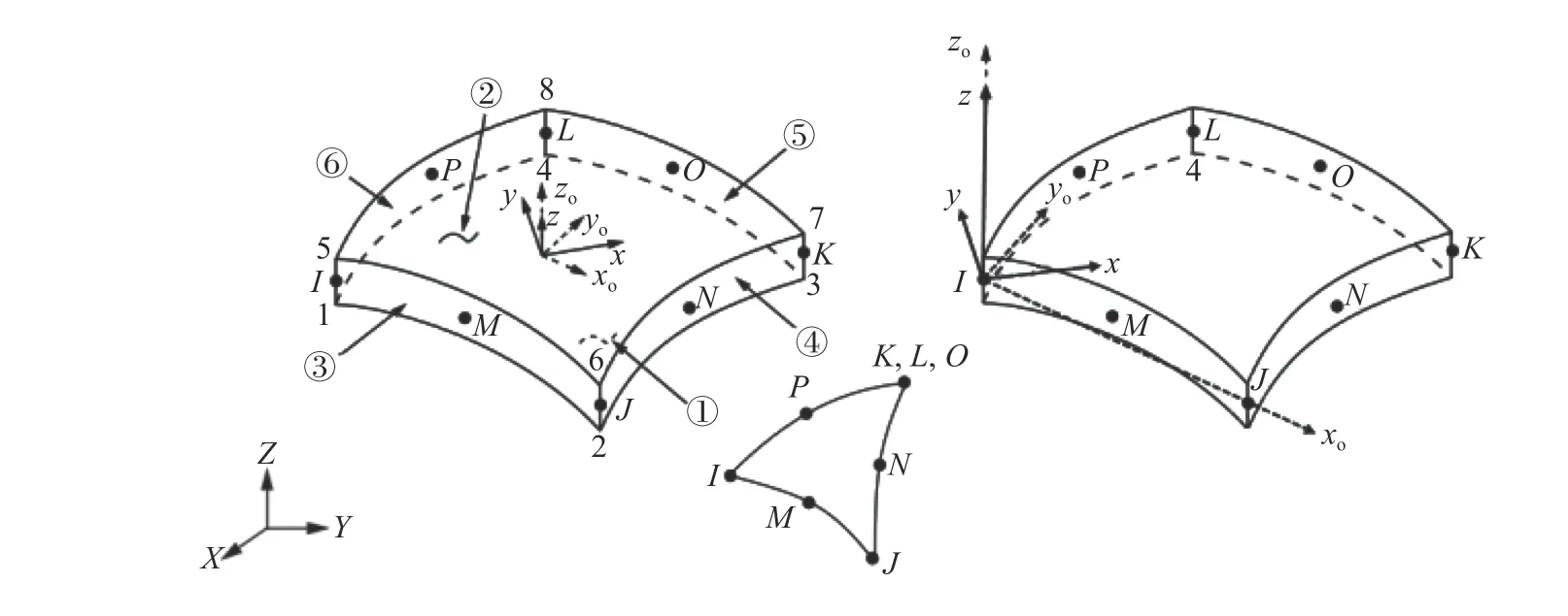
Fig. 1. Finite element SHELL281 [34]

Fig. 2. Constructal design application: a reference plate and b stiffened plate P(2, 2)
It is important to mention that the developed computational model, unlike most computational models found in the literature for stiffened plates, adopts the symmetry boundary conditions. The use of the symmetry boundary conditions allows the reduction of processing time and the use of a more refined mesh, since it is possible to consider a computational domain with half or a quarter of the problem when it presents symmetry characteristics in relation to its geometry, loading, bonding conditions and material properties. When applying the symmetry boundary conditions it is assumed that the out-of-plane translations and in-plane rotations are set to zero [34].
From the CD application it is possible to define different stiffened plate geometries, composing the search space of the analysis. To do so, a non-stiffened plate (with lengtha, widthband thicknesst) was used as reference. The total steel volume and the dimensionsaandbof the reference plate are kept constant, while a fraction of its volume (identified byφ) is transformed into stiffeners from the decreasing of its thickness(Fig. 2).
This volumetric fraction is a restriction parameter of the CD method and is defined as:

whereVsis the volume of the reference plate transformed into stiffeners,Vris the total volume of the reference plate,Nlsis the number of longitudinal stiffeners,Ntsis the number of longitudinal stiffeners,hsis the height of the stiffeners andtsis the thickness of the stiffeners.In addition to theφparameter,Nls,Nts, and ratiohs/tsare adopted as degrees of freedom of the CD method, being its variations responsible by the generation of the geometric configurations which compose the search space.So, the analysis involved plates formed by 25 combinations of longitudinal and transverse stiffeners, obeying the format P(Nls,Nts) , varying the following degrees of freedom:Nls=2, 3,4, 5, 6 andNts=2, 3, 4, 5, 6. In view of this, the following plates were analyzed: P(2, 2), P(2, 3), P(2, 4), P(2, 5), P(2, 6), P(3, 2), P(3,3), P(3, 4), P(3, 5), P(3, 6), P(4, 2), P(4, 3), P(4, 4), P(4, 5), P(4, 6),P(5, 2), P(5, 3), P(5, 4), P(5, 5), P(5, 6), P(6, 2), P(6, 3), P(6, 4), P(6,5), and P(6, 6), as illustrated in Fig. 3. Regarding the stiffeners,they have a rectangular cross-section and commercial values of thicknesses of steel plates were adopted (3.18, 4.75, 6.35, 8.00,9.53, 12.70, 15.90, 19.21, 22.20, and 25.40 mm). Besides, four geometrical constraints are imposed: (1) the height of longitudinal and transverse stiffeners are the same; (2) the height of the stiffeners cannot be greater than 0.3 m, in order to avoid geometric disproportions between the height of the stiffener and the lateral dimensions of the plate; (3) the ratiohs/tsmust be greater than 1 to prevent the thickness of the stiffener being greater than its height, which would de-characterize the stiffener which must have a height greater than its thickness; (4) as depicted in Fig. 2,the stiffeners have equidistant longitudinal spacingSlsand transverse spacingStsgiven, respectively, by

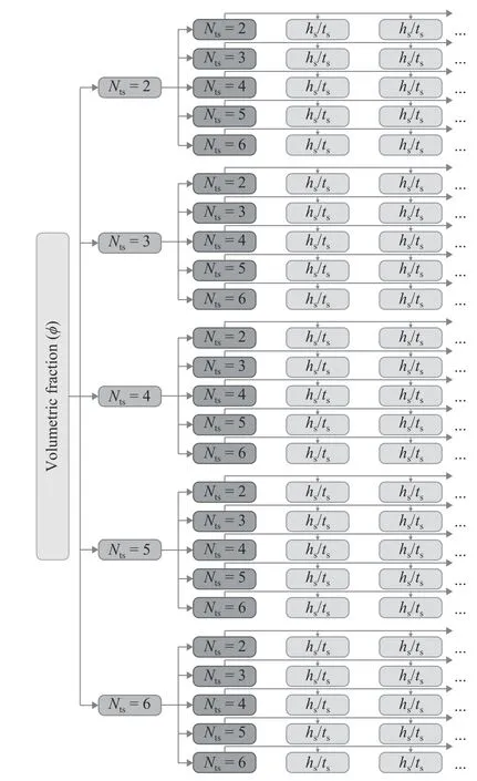
Fig. 3. Geometric on figurations generated by CD method
Concerning the reference plate, it is adopteda= 2 m,b= 1 m,andt= 20 mm, being made of structural steel A-36 with elastic modulus ofE=200 GPa, Poisson's ratio ofν=0.3 and yielding strength ofσy=250 MPa [35]. The ratio between the volume of material transformed into stiffeners and the volume of the reference plate isφ=0.3, i.e., 30% of the total steel volume is used as stiffeners (based on Ref. [13]). The edges of reference plate, as well as of the stiffened plates (including the edges of the stiffeners), are considered as clamped. For all plates a uniformly distributed transverse loading of 10 kPa is taken into account, ensuring a linear-elastic behavior.
Finally, the geometric configurations of the search space are numerically simulated and its results are compared among each other characterizing an optimization by means ES technique,being the goal the minimization of maximum deflection and minimization of maximum von Mises stress.
Therefore, before the application of the proposed methodology, it was necessary to perform the computational model verification. First, it was verified the computational model applied to the reference plate (see Fig. 2a). To do so, the analytical solution for the central deflection of a clamped plate with no stiffeners is given by [36]

whereqis the uniformly distributed transverse load. From Eq.(4) a central deflection of 0.1734 mm was obtained.
Employing the developed computational model, simulating only 1/4 of the plate due to the symmetry boundary conditions,with a converged mesh of 10296 quadrilateral SHELL281 finite elements with size of 7 mm, the central deflection of the plate was 0.1739 mm.
If compared the numerical result with the analytical one, a difference of 0.29% is achieved, verifying the developed computational model.
Next, the verification of the computational model applied to the stiffened plates was performed with a square steel plate,clamped on four sides, with two orthogonal stiffeners (Fig. 4)and subjected to a uniform transversal load of 9.8 kPa; having the following material properties:E= 210 GPa andν= 0.30. The results of the present study were compared with those presented by Salomon [7].
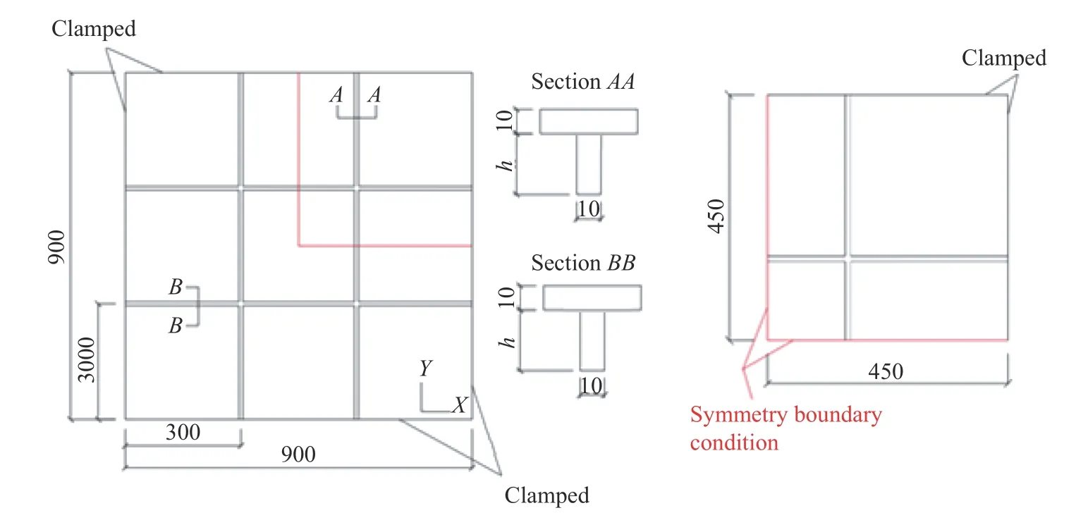
Fig. 4. Square plate with two orthogonal stiffeners (unit: mm)
According to Salomon [7] a variation in the height of the stiffenersh(see Fig. 4) from 10 to 100 mm (with an increment of 10 mm) was carried out, being the analysis based on the results of maximum displacement (w) and maximum bending stress of the stiffeners (σ).
So, to reproduce this study a mesh convergence test was developed for the entire plate and for 1/4 of the plate (with symmetry boundary conditions), as can be viewed in Fig. 4. To exemplify, Fig. 5 shows the results for the mesh convergence test for the case withh= 100 mm.
Figure 5a shows that the stabilization of the maximum deflection analysis occurred for the mesh with 2604 elements (element size of 22 mm) in the entire plate. For the plate that employs the symmetry condition, it was used a mesh with 216 elements (element size of 44 mm). Regarding the analysis of the bending stress, Fig. 5b indicates that the stabilization occurred for a mesh with 10416 elements for the entire plate and 2604 elements for the plate with symmetry. In both cases, for the stress analysis, the size of the element was 11 mm.
Mesh convergence test for the other cases (h= 10, 20, 30, 40,50, 60, 70, 80, and 90 mm) were carried out in a similar manner to that presented in Fig. 5 for the caseh= 100 mm. So, the obtained results in all mesh convergence tests are presented in Table 1.

Fig. 5. Mesh convergence test for the case with h = 100 mm. a Maximum displacement and b maximum bending stress
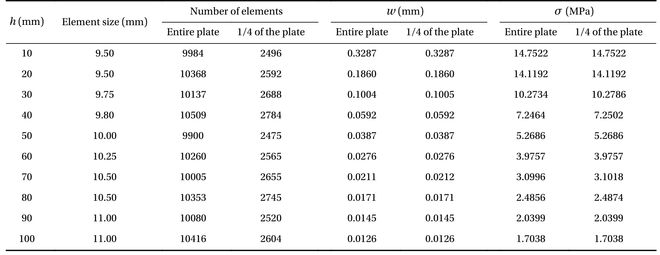
Table 1 Size of the simulated element for the entire plate and the plate with symmetry
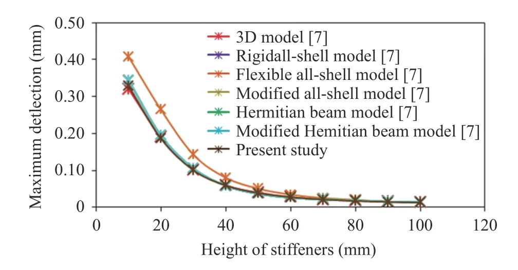
Fig. 6. Computational model verification for maximum deflection
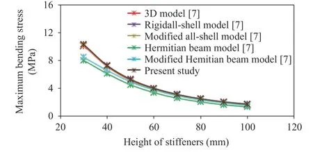
Fig. 7. Computational model verification for maximum bending stress
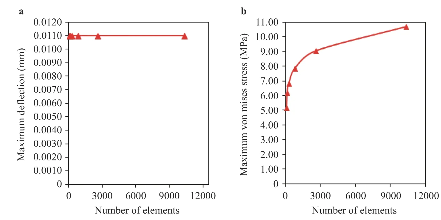
hs/tsFig. 8. Mesh convergence test for a maximum deflection and b von Mises stress of the plate P(6, 6) with = 66.3476 with symmetry
It is important to highlight that, as expected, the converged mesh adopted for each case (see Table 1) was defined by the mesh convergence test related with the maximum bending stress. In addition, also in Table 1, one can observe that the numerical results for both maximum out-of-plane displacement and maximum bending stress considering 1/4 of the plate conduct to very similar values to those obtained with entire plate.
Thereafter, the numerical results obtained by the proposed model with the converged meshes were compared to those presented by Ref. [7], being Figs. 6 and 7 related to maximum deflection and maximum stress, respectively.
Figures 6 and 7 indicate, respectively, that the results of deflection and stress obtained in the present study are in good agreement with the results presented in Ref. [7]. Among the computational models adopted in Ref. [7], the most accurate is the 3D model. Then, using the 3D model as a reference, it was reached a maximum difference for the deflection analysis around 6% and a maximum difference for the stress analysis around 5%, which occurs for the highest values ofh(90 and 100 mm). From these comparisons, it is possible to affirm that the developed computational model was adequately verified.
Despite the performed verification, it is well known that the ideal way for the accuracy evaluation of a computational model is by means a validation, i.e., the comparison of its numerical results with experimental data. However, for the present work no adequately experimental cases were found.
From the computational model verifications, the earlier proposed methodology it was applied in a case study. To do so, a mesh convergence test was developed considering the stiffened plate with greater geometric complexity among all configurations of search space, i.e., the plate P(6, 6) withhs/ts= 66.3476.Figure 8 shows the numerical results for the mesh convergence test concerning the maximum deflection (Fig. 8a) and the maximum von Mises stress (Fig. 8b) analysis for the plate P(6, 6) withhs/ts= 66.3476. For the deflection analysis it was possible to determine the solution of mesh independence, as can be observed in Fig. 8a. The used mesh required 91 elements with a size of 384 mm. However, for the von Mises stress analysis the results indicated a need for the use of more refined meshes due to the nonstabilization of the test.
Therefore, from Fig. 8 one can observe an excellent meshconvergence for the deflection analysis (Fig. 8a); while for the von Mises stress a stabilization trend can be observed (Fig. 8b),but being necessary more refined meshes to obtain the convergence. The ANSYS 18.2 academic version limits the computational modeling to a maximum use of 32000 nodes per simulation. For this reason, the more refined possible mesh was employed for each geometric configuration numerically simulated in this work, as indicated in Table 2. Therefore, the maximum value of the von Mises stress was used only as a means of comparison, and not as definitive value.
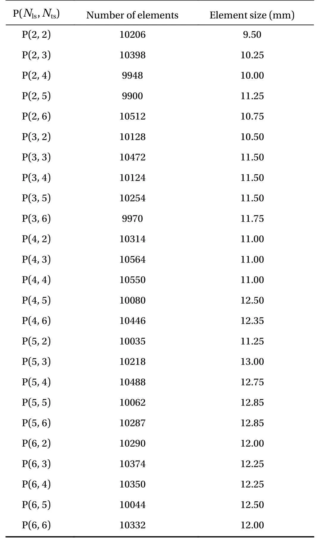
Table 2 Finite element size SHELL281 used in each P(Nls,Nts)

Fig. 9. Variations of the maximum deflection as a function of hs/ts for a Nls=2, b Nls=3, c Nls=4, d Nls=5, and e Nls=6
Thereafter, employing the verified model, the proposed geometries by means CD were numerically simulated with spatial discretization indicated in Table 2. From the obtained results,scatter plots were generated with maximum deflection (Fig. 9)and maximum von Mises stress (Fig. 10) for each geometric comb.ination P(Nls,Nts) as a function of the degree of freedomhs/ts
Figure 9 indicates that the transformation of 30% of reference plate volume into stiffeners always leads to an improvement over deflection, i.e., all stiffened plates have a smaller maximum deflection than the reference plate. In turn, for the maximum von Mises stress (Fig. 10), it can be noted that there is a specific value ofhs/ts from which it is possible to obtain astiffened plate with a superior performance than the referenceplate. For instance, in Fig. 10a thishs/tsvalue is value is approximately 5,having several configurations submitted to smaller stress than reference plate. On the other hand, in Fig. 10e only the plate P(6,6) withhs/ts= 66.3476 reached a stress slightly smaller than reference plate. However, for values ofhs/tssmaller than these specific magnitudes, there was an increase in the maximum stress and, consequently, a worsening in the stress mechanical behavior if compared with reference plate.
Another observed aspect is that as the value ofhs/tsincreases, the deflection (Fig. 9) and the von Mises stress (Fig. 10)of the stiffened plates decrease. An explanation for this, as previously observed in Ref. [13], is due the increase in the moment of inertia of the cross-section of the new structures formed.
Next, Table 3 shows the best geometric configurations for each P(Nls,Nts), i.e., the stiffened plates that minimized the deflection and von Mises stress of each combination of longitudinal and transverse stiffeners addressed in this study.
Observing Table 3, it was noticed that P(2, 6) withhs/ts=53.4905 has the minimum value for the maximum deflection, being 95.23% smaller than the maximum deflection of reference plate. About the stress analysis, P(2, 5) withhs/ts= 59.4087 is the best geometry, achieving a stress reduction of 44.98% if compared with the reference plate.
From Table 3, the influence ofNtsover the performance indicators is depicted in Fig. 11. It was inferred that whenNtsincreases, in a general way, occurs a decrease of the maximum deflection and a decrease of the maximum von Mises of the stiffened plates.
Finally, in Fig. 12 was carried out a qualitative evaluation of the deflected configuration for the reference plate (Fig. 12a),plate P(6, 2) withhs/ts= 1.3581 (worst geometry for deflection purpose, in Fig. 12b), and plate P(2, 6) withhs/ts= 53.4905 (best geometry for deflection purpose, in Fig. 12c). In a similar way,Fig. 13 shows the von Mises stress distribution of reference plate(Fig. 13a), plate P(6, 3) withhs/ts= 1.2790 (worst geometry for the stress purpose, Fig. 13b), and plate P(2, 5) withhs/ts=59.4087 (best geometry for stress purpose, Fig. 13c).

Fig. 10. Variations of the von Mises maximum stress as a function of h s/ts for a N ls=2 , b N ls=3 , c N ls=4 , d N ls=5 , and e Nls=6
From Fig. 12, the stiffened plate P(6, 2) withhs/ts= 1.3581(Fig. 12b) has a global deflection mechanical behavior quite similar to that of the reference plate (Fig. 12a); while the best plate P(2, 6) has local deflections among the stiffeners. This fact occurs due to the regions confined among stiffeners that behave like small square plates supported in its four edges (due to the highratio), allowing the rigidity improvement. This same trend can be observed in Fig. 13, where the best geometry also has an elevatedvalue and the almost square regions formed by the stiffeners arrangement, allowing the improvement of mechanical resistance.
Based on the presented results, it was possible to determine a time gain in the computational processing of the simulations,because the proposed model reduces the computational domain of the problem and, as a consequence, needs fewer finite elements for their spatial discretization. For example, adopting a quadrilateral SHELL281 finite element with size of 24 mm, theplate P(6, 6) with= 66.3476 showed a reduction in computational processing time of 75.38%, since the plate with symmetry requires only 1.00 s to solve the equations of 2583 elements; while the model that considers the entire plate as computational domain required 4.06 s to solve the equations of 10332 finite elements. Regarding the random access memory (RAM) of the computer allocated to solve these models, the entire plate model used 747.25 MB, while the developed model using symmetry boundary conditions needed only 162.30 MB, demonstrating a reduction of 78.28% in the RAM.
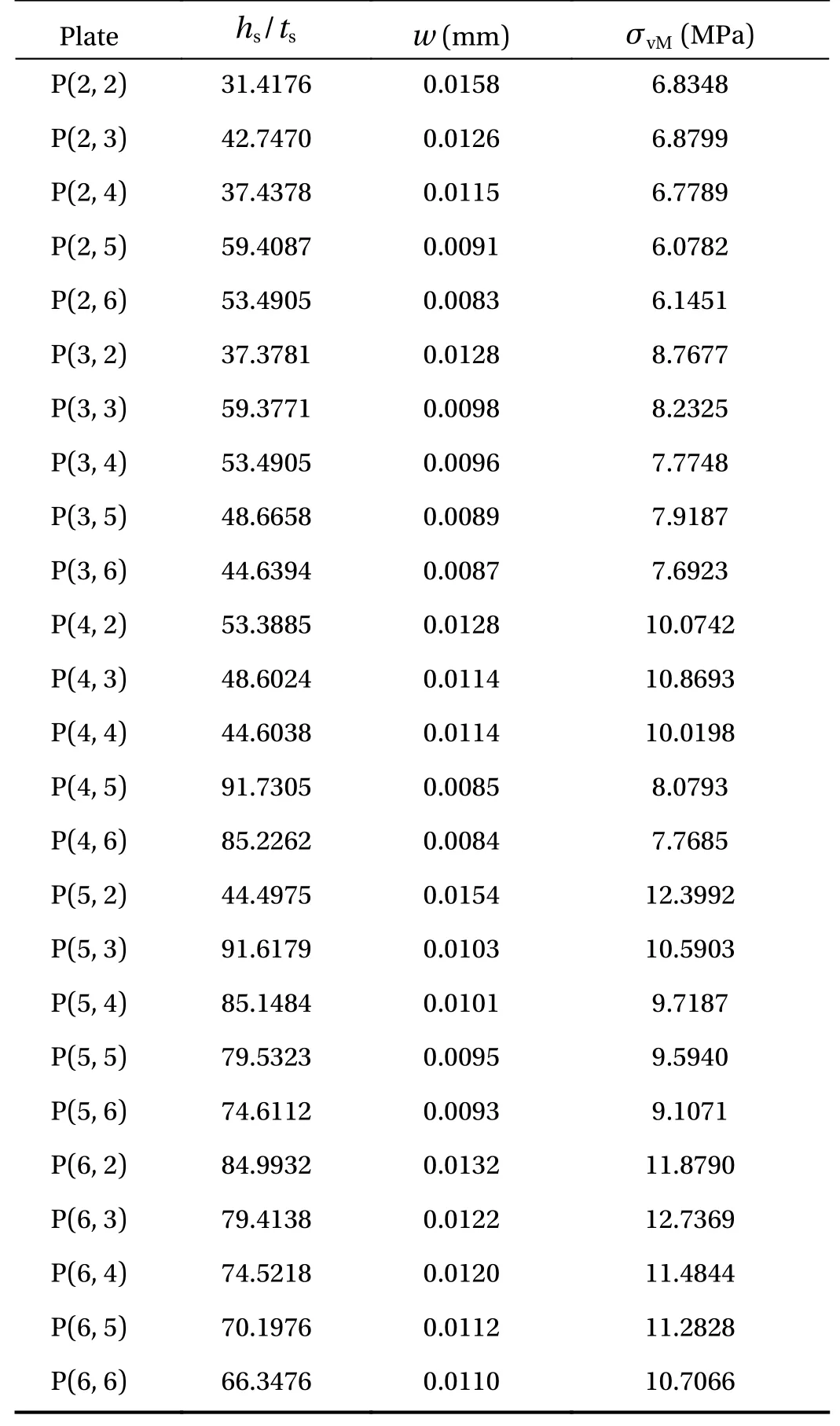
Table 3 Best geometric configurations for each P(Nls,Nts)
Moreover, the CD method and the Exhaustive Search technique were used in conjunction with the developed computational model aiming to define the best geometric configurations that minimize the deflection and minimize the stress of clamped stiffened steel plates subjected to uniformly distribute transverse load. It has been shown that the transformation of 30% of the volume of a non-stiffened reference plate into longitudinal and transverse stiffeners can results in an improvement of structural mechanical performance. It was also observed that in addition to the number of longitudinal stiffenersNlsand transverse stiffenersNts, the ratio of stiffener height per stiffener thicknesshs/tshad a strong influence on the rigidity and resistance of the stiffened plates. For the performed stress analysis, thehs/tsvariation was the geometric parameter that defined if the stiffened plate achieved or not a superior performance than the reference plate. Regarding the improvement on the deflections, all stiffened plates reached a smaller deflection than the reference plate; with the increasing of thehs/tsratio conducting to the deflection reduction. Among all search space configurations and considering the proximity for the deflections and stress results, it is possible to indicate the stiffened plates P(2, 5) and P(2, 6) as the optimized geometries for the improvement of mechanical behavior.
Finally, the study of different geometric configurations with the same volume of material proved that the simple increase in the number of stiffeners does not always imply in the mechanical behavior improvement of stiffened plates, evidencing the importance of the geometric evaluation in this type of structural component.
Acknowledgement
This study was financed in part by the CAPES (Coordination for the Improvement of Higher Education Personnel), finance code 001. The authors also thank FAPERGS (Foundation for Research Support of the State of Rio Grande do Sul), CNPq (Brazilian National Council for Scientific and Technological Development) and the Italian Minister of Foreign Affairs and International Cooperation (MAECI), as part of the "Two Seats for a Solar Car" international project.
杂志排行
Theoretical & Applied Mechanics Letters的其它文章
- A unidirectional SH wave transducer based on phase-controlled antiparallel thickness-shear (d15) piezoelectric strips
- A novel method for investigation of acoustic and elastic wave phenomena using numerical experiments
- A note on a family of proximal gradient methods for quasi-static incremental problems in elastoplastic analysis
- Modeling rock fragmentation by coupling Voronoi diagram and discretized virtual internal bond
- Dynamic mode decomposition and reconstruction of transient cavitating flows around a Clark-Y hydrofoil
- Numerical investigations to design a novel model based on the fifth order system of Emden-Fowler equations
