A novel method for investigation of acoustic and elastic wave phenomena using numerical experiments
2020-11-04AlenaFavorskayaIgorPetrovc
Alena Favorskaya*, Igor Petrovc
a Moscow Institute of Physics and Technology, Dolgoprudny, Moscow region, Russian Federation
b Scientific Research Institute for System Analysis of the Russian Academy of Sciences, Moscow, Russian Federation
c Xi'an Jiaotong University, Xi'an 710049, China
Keywords: Elastic waves Acoustic waves Waves scattering Fractures Seismic prospecting
ABSTRACT The emergence of new types of composite materials, the depletion of existing hydrocarbon deposits, and the increase in the speed of trains require the development of new research methods based on wave scattering. Therefore, it is necessary to determine the laws of wave scattering in inhomogeneous media. We propose a method that combines the advantages of a numerical simulation with an analytical study of the boundary value problem of elastic and acoustic wave equations. In this letter we present the results of the study using the proposed method: the formation of a response from a shear wave in an acoustic medium and the formation of shear waves when a vertically incident longitudinal wave is scattered by a vertical gas-filled fracture. We have obtained a number of analytical expressions characterising the scattering of these wave types.©2020 The Authors. Published by Elsevier Ltd on behalf of The Chinese Society of Theoretical and Applied Mechanics. This is an open access article under the CC BY-NC-ND license(http://creativecommons.org/licenses/by-nc-nd/4.0/).
A theoretical study of elastic and acoustic wave phenomena in media with complex structures can help solve many practical problems in the fields of seismic exploration and ultrasonic nondestructive testing. For a theoretical study of wave phenomena,exact analytical expressions are used for particular solutions of wave equations [1, 2] and the modelling of measurements results, i.e., seismograms, ultrasonic sensors data, etc. The theory of constructing analytical expressions is usually based on Fourier transform [3]. Methods for modelling wave phenomena can be divided into two classes: full-wave modelling methods that allow for solving boundary-value problems of the elastic and acoustic wave equations in the time domain [4] and ray tracing methods [5]. There are many numerical methods for modelling wave phenomena. Modern advanced research methods include the boundary element method [6], the finite element method[7-9], the discontinuous Galerkin method [10] and the spectral element method [11]. Some studies combine an analytical and computational approach by comparing the final results for example [12]. In this letter we propose a combined method for studying wave phenomena, in which a comparison between analytical expressions and the results of numerical experiments is carried out at the derivation stage of these analytical expressions.
When applying full-wave modelling, all types of scattering are present. However, due to the huge amount (hundreds of TBs on a hard disk) of calculated data, the interpretation of the results of computational experiments is significantly complicated.The Poynting vector is used to separate waves into longitudinal(P-) and shear (S-) waves [13], however, this technique does not work well in cases of multiple interference, nor for surface waves. It also does not allow the researcher to form a complete understanding of wave dynamics and complicates the search for wave phenomena, which are previously not used in practice.
We propose a method called wave logica, combining the advantages of analytical research of wave phenomena and fullwave modelling (Fig. 1). A numerical method is used to model wave phenomena in the time domain, for example, the gridcharacteristic method [14]. A detailed calculation grid is used.Then, sections of wave fields (snapshots) inside the object under study are drawn and analysed in dynamics, determining various types of waves [14, 15]. One thus obtains either methods that can be used in practice for a wide class of mechanical-mathematical models, or analytical expressions characterising the identified wave phenomenon. The obtained methods and analytical expressions are tested using numerical experiments on synthetic data (Fig. 2).
Thus, the advanced method allows reducing the amount of mathematical framework by simpler obtaining the exact analytical expression needed to develop a novel technology. For example, to develop a new method of seismic imaging or ultrasonic non-destructive testing of rails, only a formula relating the scattering angles and the type of scattered wave depending on the elastic parameters and reflector geometry may be sufficient,and the reflection and transmission coefficients can be neglected. For other technical solutions, reflection and transmission coefficients are needed, but the proposed method allows obtaining them without explicitly writing out the exact analytical solution of the boundary value problem under consideration.This gives advantages, since in spite of the fact that for many practical models the exact solution of a boundary value problem consists of a superposition of known solutions, and there are a lot of these particular solutions, and the final solution is too complicated, see Refs. [14, 15]. The use of wave patterns makes it possible to establish compliance between each particular solution and line at wave patterns according to specific rules and to avoid using a complete record of the superposition of these particular solutions.
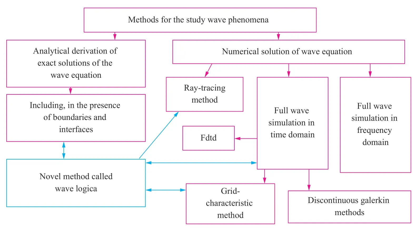
Fig. 1. Place of the novel wave phenomena investigation method (marked with turquoise) among the well-known methods. Interrelations between different methods are shown by arrows.
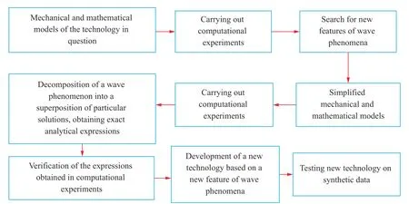
Fig. 2. Proposed scheme of the novel wave phenomena investigation method for the development of a new technology.
The application of the proposed method for studying wave phenomena can be described as follows: initially, a series of simplified mechanical-mathematical models is developed. For this series of simplified models, computational experiments are carried out, the wave fields of the velocity module and/or velocity components and the Cauchy stress tensor components are visualised, and snapshots of wave fields (wave patterns) are obtained. Features of the construction of these wave patterns are described in Ref. [16]. These wave patterns are then analysed and the types of waves and angles at which these waves move relative to the considered boundaries and contact boundaries are determined. The components of the velocity and the Cauchy stress tensor of each wave in the original coordinate system are then analytically determined using the initial relations for the amplitudes and the vector and tensor components' transformation formulae during rotation. The obtained components of the velocity and the Cauchy stress tensor in each wave in the original coordinate system are checked by correlation with the simulated wave patterns, and the obtained components are substituted into the boundary conditions. Finally, accurate analytical expressions relating the amplitudes are derived. If it turns out that the problem contains critical parameters, a series of simplified mechanical-mathematical models is modified, and the whole algorithm of actions is repeated again. Analytical expressions relating amplitudes are checked for accuracy by correlation with wave patterns. Thus, the proposed method for studying wave phenomena consists of the joint use of numerical modeling (not necessarily the grid-characteristic method), certain rules for visualizing and interpreting calculated wave fields, and using analytical calculations to obtain accurate analytical expressions. Moreover, at certain stages of the derivation of analytical expressions, a comparison with the results of numerical experiments is used in accordance with Fig. 3.
The types of waves in visualised wave fields (wave patterns)can be determined by the propagation velocity, by the shape of the wave front, by localisation in space (for example, surface waves are dampened in volume), by the visible width of the wave front, by the direction of media oscillations in the wave, or by relations between the signs of the components of the velocity and the Cauchy stress tensor.
Further, we present the results of a study using this method of S-wave scattering at the boundary between an elastic and acoustic medium (Problem 1) and of plane P-wave scattering by a gas-filled fracture located along the wave front (Problem 2).The response from a shear wave in an acoustic medium was used to develop a new method for offshore seismic exploration.Shear responses from a vertically incident wave on a vertical fracture are important for the development of non-destructive ultrasonic testing methods of railway tracks and other objects.Coupled transmission of elastic waves and acoustic waves in a Tjoint was also investigated in Ref. [17] using the analytical method.
In order to obtain wave patterns for Problems 1 and 2 we used the numerical grid-characteristic method. The results of comparison of the grid-characteristic method with accurate analytical solutions and with other numerical methods one can find in Refs. [14, 18, 19].
In Problem 1 we consider the following problem statement illustrated in Fig. 4. A plane S-wave propagates from the lower half of the figure to the upper. In the upper half we solve the acoustic wave equation given by

In the lower half we solve the elastic wave equation given by the following formulae:

In Eqs. (1)-(4) and further in the letter v (r,t),p(r,t), andσ(r,t) are unknown functions of timetand position vector r,i.e., velocity (derivative of displacement with respect to time),pressure, and Cauchy stress tensor;ρis material density;cis speed of sound;cPis speed of P-waves;cSis speed of P-waves;⊗marks tensor production,(a⊗b)ij=aibj.
We use the following boundary conditions on the interfacebetween elastic and acoustic media:

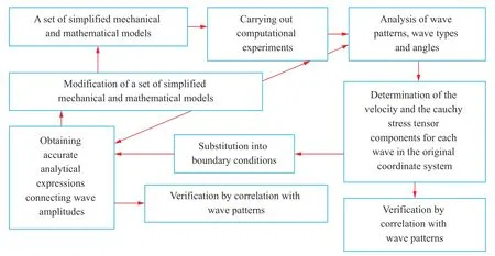
Fig. 3. Proposed scheme of obtaining accurate analytical expressions using computational experiments.

In Eqs. (5)-(7) and further in the letteris a unit vector of the outer normal to the boundary of elastic medium,is velocity in elastic medium,is velocity in acoustic medium.
In the results of these experiments various types of plane waves were revealed, shown in Fig. 4. When an S-wave in an elastic medium propagates to the interface at an angle α of inclination of the wave front, some of the oscillations are transmitted to the acoustic layer, forming a response: a P-wave propagating at an angleβbetween its front and the interface. We called these responses from S-waves in acoustic media rS-waves. One can calculate the angleβusing the following formula:

Reflected SS-waves, head S-waves, and reflected PS-waves also arise in an elastic medium. The angle between the front of the PS-wave and the interface can be found by the following expression:

Numerical experiments with varying parameters showed that in Problem 1 there are two critical speeds of sound:cCR1=cSandcCR2=cPin an acoustic medium, and two critical angles between the front of the incident S-wave and the interface. One can calculate these critical angles using the following formulae:
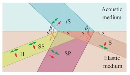
Fig. 4. S-wave scattering on the boundary between elastic (in beige)and acoustic (in turquoise) media; incident S-wave (in beige), reflected longitudinal SP-wave (in red), head H-wave (in yellow), and shear SS-wave (in yellow), transmitted longitudinal rS-wave (in turquoise); red arrows correspond to wave propagation direction,green arrows correspond to medium vibration direction into the wave.

Moreover, the second critical angleexists only under the following condition:

Thus, depending on the parameters, the types of waves that appear in Problem 1 are shown in Fig. 5.
We have carried out numerical experiments for all 19 cases noted in Fig. 5, varying the speed of sound in an acoustic medium and the angle of incidence of the S-wave. We used an acoustic medium with the speed of sound equalled to 1500 m/s and density equalled to 1000 kg/m3. We give the elastic parameters of the elastic media in Table 1. In Figs. 6-14 we present the results of some numerical experiments, demonstrating various cases indicated in Fig. 5. Black arrows correspond to wave propagation directions and white arrows correspond to medium oscillation directions. The H-wave is not marked in Figs. 6-14, since its front geometrically coincides with the SS-wave front.
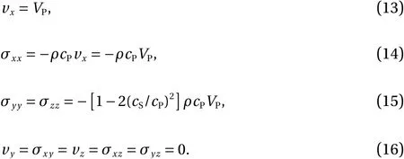
Taking into account the revealed angles and the results of numerical experiments, we obtained the scattering amplitudes based on the following expressions for the elastic P-waves' components:
S-waves' components:

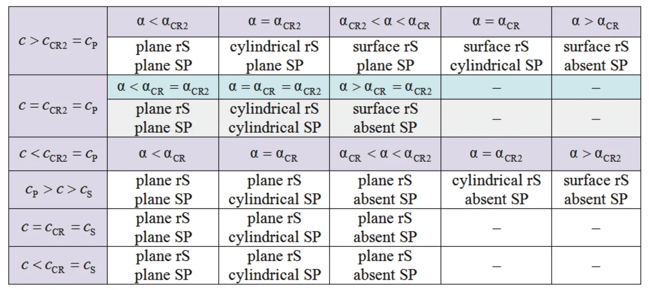
Fig. 5. Types of waves in Problem 1, depending on the critical speeds of sound in an acoustic medium and the critical angles α. Dashes indicate impossible cases. SS-waves are plane in all cases.

and acoustic P-waves' components:
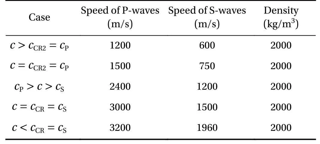
Table 1 Elastic characteristics of elastic media in Problem 1
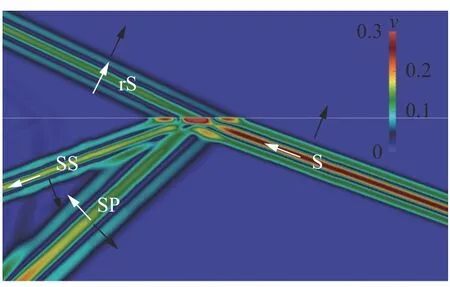
Fig. 6. Wave field snapshot of velocity module,cP=cCR2>c>cCR=cS, α <αCR, plane rS-wave, plane SP-wave.
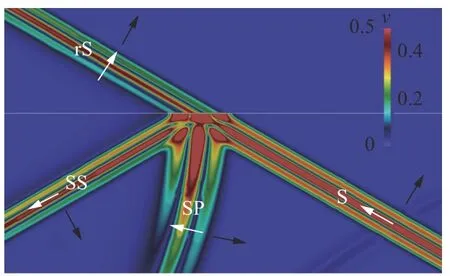
Fig.7.Wave field snapshot of velocity module, c =cCR=cS ,α=αCR,plane rS-wave, cylindrical SP-wave..
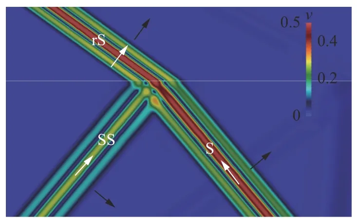
Fig. 8. Wave field snapshot of velocity module, c <cCR=cS ,α=αCR , plane rS-wave, absent SP-wave.
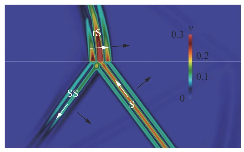
Fig. 9. Wave field snapshot of velocity module,c P=cCR2>c>cCR=cS, α =αCR2, cylindrical rS-wave, absent SP-wave.
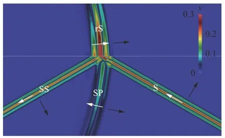
Fig. 10. Wave field snapshot of velocity module, c =cCR2=cP ,α=αCR=αCR2, cylindrical rS-wave, cylindrical SP-wave.
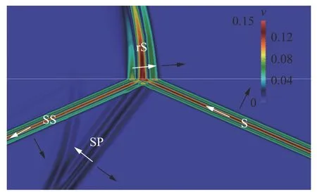
Fig. 11. Wave field snapshot of velocity module, c >cCR2=cP ,α=αCR2, cylindrical rS-wave, plane SP-wave.
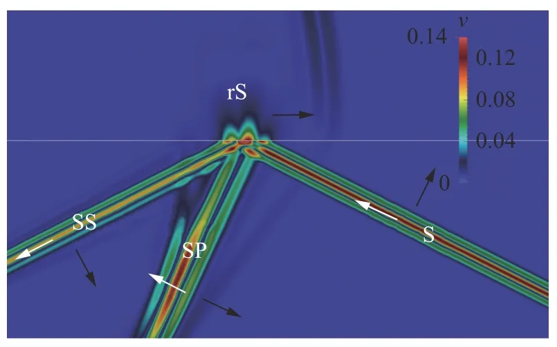
Fig. 12. Wave field snapshot of velocity module, c >cCR2=cP ,αCR2<α<αCR , surface rS-wave, plane SP-wave.

In Eqs. (13)-(22)VP,VS, andVAare amplitudes of elastic Pwaves, S-waves, and acoustic P-waves, respectively.
The scattering amplitude rS-wave has the greatest practical value. We give the corresponding formulae in this letter:
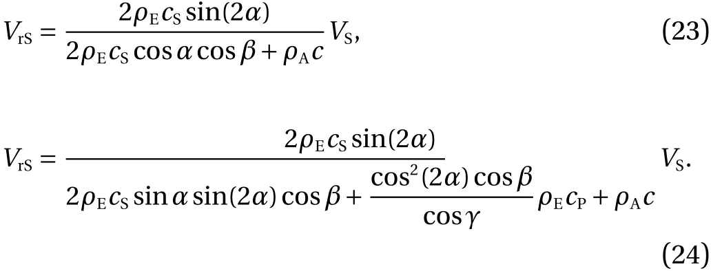
Equation (23) is valid if one of the Eq. (25) or (26) is true,when SP-wave is absent (Fig. 5)

Equation (24) is valid if one of the Eq. (27) or (28) is true,when SP-wave contributes to the reflection (Fig. 5)

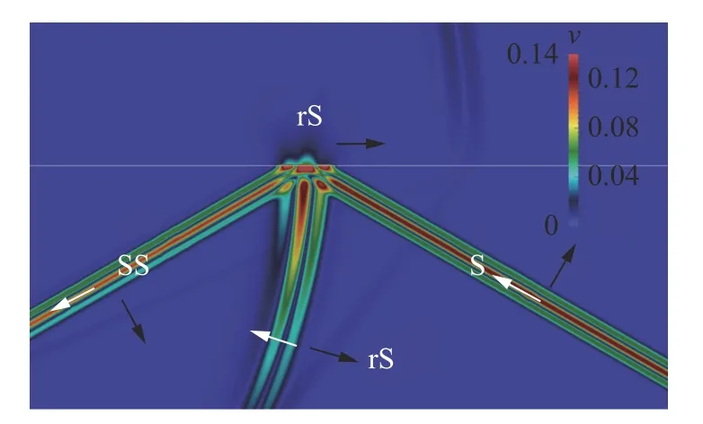
Fig. 13. Wave field snapshot of velocity module, c >cCR2=cP ,α=αCR , surface rS-wave, cylindrical SP-wave.
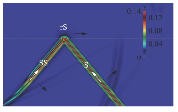
Fig. 14. Wave field snapshot of velocity module, c >cCR2=cP ,α>αCR , surface rS-wave, absent SP-wave.

In Eqs. (23) and (24),VSis the incident S-wave amplitude,VrSis the reflected longitudinal rS-wave amplitude in acoustic media,ρEis elastic material density,ρAis acoustic material density,andαis the angle between the incident S-wave front and the boundary. Anglesare given by Eqs. (8) and (9) respectively.
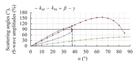
Fig. 15. Graphs of the percentage relationship between velocity modules in rS-wave and in S-wave, and scattering angles,c<cCR=cS.
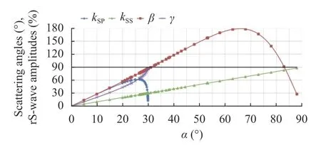
Fig. 16. Graphs of the percentage relationship between velocity modules in rS-wave and in S-wave, and scattering angles,c=cCR=cS.
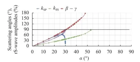
Fig. 17. Graphs of the percentage relationship between velocity modules in rS-wave and in S-wave, and scattering angles,cCR2=cP>c>cS=cCR1.
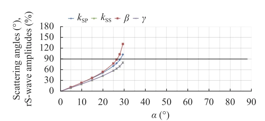
Fig. 18. Graphs of the percentage relationship between velocity modules in rS-wave and in S-wave, and scattering angles,c=cCR2=cP.
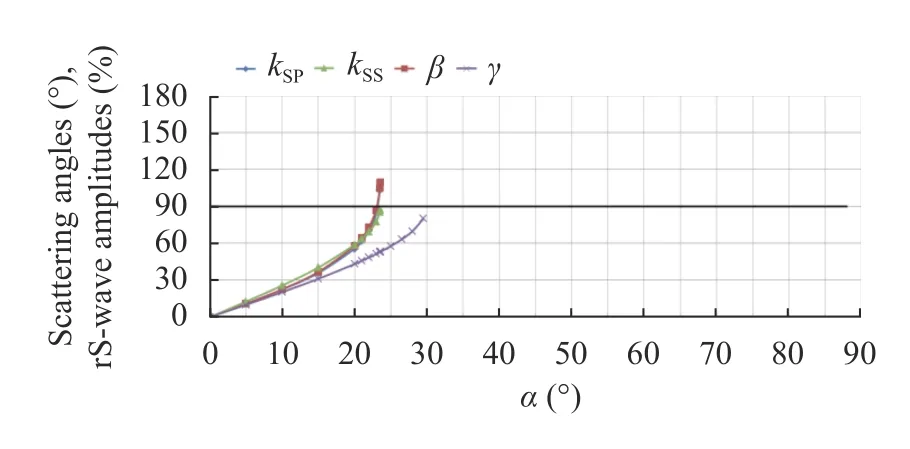
Fig. 19. Graphs of the percentage relationship between velocity modules in rS-wave and in S-wave, and scattering angles,c>cCR2=cP.
It can be seen that for all cases the numerical values are in accordance with Eq. (23) and are close to numerical values in accordance with Eq. (24). Therefore, only Eq. (23) can be used for estimates. Note that thekSSandkSPin excess of 100% does not contradict the law of conservation of energy, since the formulae are given for the ratio of the amplitudes of velocities, not energies.
In Problem 2 we solve the system of Eqs. (3) and (4) in the space with the given fracture into it. At the fracture boundaries,we use the free boundary condition in accordance with

in which, f is the traction, n is a unit vector of the inner normal to the boundary of the fracture.
We have paid attention to the scattered S-waves arising in this problem (Fig. 17).
For the development of non-destructive testing methods, the relationship between the characteristics of the scattered SSwaves and the fracture length as well as the motion geometry of the scattered SS-waves are of the greatest importance. We give below the corresponding expressions:

In Eqs. (30)-(32),Lis fracture length,Dis the reflected Swave front extension,θis the angle between the S-wave front and the fracture,are P- and S-wave widths respectively.
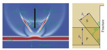
Fig. 20. Wave field snapshot of velocity module for Problem 2 (on the left side). Green arrows mark wave propagation directions.White lines mark the fracture. SL- and SR-waves are left and right reflected S-waves respectively. Scheme for determining the angle is on the right side.
The scattering angles in both problems were determined as follows, using the angleθfrom Problem 2 as an example: The wave field perturbation duration along the fracture boundary(Fig. 20) should be the same for the incident P-wave and reflected S-wave. The relationship between the width of their fronts is known for having the same wavelet shape (Eq. (31)). In this way,a geometrically accurate expression forθcan be obtained in accordance with the drawing at the right side of Fig. 20.
The obtained results are applicable for a frequency range in which the vibration of materials is correctly described by systems of Eqs. (1) and (2) or Eqs. (3) and (4). Usually, the propagation of waves in geological media is described by these systems of equations for the frequency range from 1 Hz to 200 Hz [20, 21].The results obtained demonstrate the effectiveness and advantages of the proposed method for studying wave phenomena using computational experiments. The results of the study of the formation of the response from shear waves in water presented in the letter are applicable for solving problems of seismic exploration on the shelf [16], since the analysis of the data of responses from shear waves will make it possible to obtain information on S-waves arising in the geological rock without using bottom stations, instead obtaining information directly from feedback in the water. The results of the study of scattering of plane P-waves on gas-saturated cracks located along the movement of these P-waves presented in the letter are of importance for modifying the non-destructive testing of railway tracks [22],since these type of cracks, without taking into account this response, can fall into the blind zone of tester equipment.
The proposed wave phenomena investigation method can be used to find exact analytical expressions characterizing the accurate solution of boundary value problems, in the case then an accurate solution of boundary value problems is a superposition of previously known and possibly unknown particular solutions.For example, the proposed method can be used to develop novel approaches of seismic imaging and ultrasonic non-destructive testing because the considered boundary value problems of the elastic and acoustic wave equations have the desired property.
Acknowledgement
This work was performed at Moscow Institute of Physics and Technology and supported by the Russian Science Foundation(Grant 19-11-00023).
杂志排行
Theoretical & Applied Mechanics Letters的其它文章
- A unidirectional SH wave transducer based on phase-controlled antiparallel thickness-shear (d15) piezoelectric strips
- A note on a family of proximal gradient methods for quasi-static incremental problems in elastoplastic analysis
- Modeling rock fragmentation by coupling Voronoi diagram and discretized virtual internal bond
- Dynamic mode decomposition and reconstruction of transient cavitating flows around a Clark-Y hydrofoil
- Numerical investigations to design a novel model based on the fifth order system of Emden-Fowler equations
- Ultrasound calibration with ladder phantom at multiple depths for breast biopsy navigation system
