Modeling rock fragmentation by coupling Voronoi diagram and discretized virtual internal bond
2020-11-04SaiLiuZhennanZhang
Sai Liu, Zhennan Zhang*
School of Naval Architecture, Ocean and Civil Engineering, Shanghai Jiao Tong University, Shanghai 200240, China
Keywords: Rock fragmentation Block smash Voronoi diagram Discretized virtual internal bond Fracture
ABSTRACT The rock fragmentation involves the inter-block and the intra-block fracture. A simulation method for rock fragmentation is developed by coupling Voronoi diagram (VD) and discretized virtual internal bond (DVIB). The DVIB is a lattice model that consists of bonds. The VD is used to generate the potential block structure in the DVIB mesh. Each potential block may contain any number of bond cells. To characterize the inter-block fracture, a hyperelastic bond potential is employed for the bond cells that are cut by the VD edges. While to characterize the intra-block fracture, an elastobrittle bond potential is adopted for the bonds in a block. By this method, both the inter-block and intra-block fracture can be well simulated. The simulation results suggest that this method is a simple and efficient approach to rock fragmentation simulation with block smash.©2020 The Authors. Published by Elsevier Ltd on behalf of The Chinese Society of Theoretical and Applied Mechanics. This is an open access article under the CC BY-NC-ND license(http://creativecommons.org/licenses/by-nc-nd/4.0/).
In the geotechnical engineering, the rock fragmentation is often encountered, e.g., the rock burst, the landslide. It involves both the macro fracturing process that occurs between blocks and the micro fracturing process that occurs within blocks. How to simulate the rock fragmentation has been a tough and challenging issue. The challenge lies in that the fragmentation involves with the dynamic fracturing process of the large displacement and the rigid body rotation. It would be very hard to simulate the fragmentation behaviors by using the conventional continuum method. Jiang et al. [1, 2] coupled the finite element method with the smoothed particle hydrodynamics together to simulate the rock fragmentation induced by water jet. Gong et al.[3] used the discrete element method and Liu et al. [4] used a 2D Voronoi element-based numerical manifold method to simulate the rock fragmentation. These methods can simulate the rock fragmentation in which an integrated rockmass body is fragmented into blocks. However, the rock fragmentation involves the multiscale fracturing processes in that beside the inter-block fracture that occurs between blocks, the block itself is also fractured. The fracture that occurs in a block is here termed as intrablock fracture. Hence, to model the rock fragmentation, both the inter-block and the intra-block fracture should be accounted.The conventional discrete element method can well simulate the inter-block fracture, but is very hard to simulate the intra-block fracture. The intra-block fracture is a mechanical process that happens on the micro scale. The lattice method pioneered by Hrennikoff [5] provides an efficient approach to fracture simulation. It discretizes a continuum into a lattice bond system, transforming a 3D continuum fracture issue into a 1D bond rupture problem. Hence, the lattice method can avoid many difficulties that the continuum-mechanics methods encounter. Due to its advantages in fracture simulation, many lattice bond methods have been developed [6-9]. The lattice method can well simulate the fracturing process, but it cannot well simulate the rock fragmentation process by itself because it has no potential block structure. Different from these lattice models, Zhang [10] developed the discretized virtual internal bond (DVIB) model,which considers a solid to consist of bond cells. Each bond cell can take any geometry with any number of bonds. If each bond cell can be considered as mineral grain, DVIB can represent the mesostructural features of a rock. The DVIB can well simulate the dynamic fracturing process of the large displacement and large deformation [11, 12], but it still cannot simulate the rock fragmentation because no block structure is represented in it. In this letter, we will extend the DVIB to the fragmentation simulation. It is done by coupling the Voronoi diagram (VD) [13, 14]and DVIB together. The VD is used to generate the potential block structure based on the background DVIB mesh. The cohesion between macro blocks and that between micro material particles are characterized by different bond potentials.
Modeling idea
The microstructure of a DVIB solid is shown in Fig. 1. It consists of bond cells. Each bond cell has finite number of bonds.The interaction between particles are characterized by a bond potential, which intrinsically contains the micro fracturing mechanism. The total strain energy of a bond cell reads

whereWis the total strain energy of bond cell;Φ(l) is the bond potential withlbeing the bond length.
The constitutive relation of a bond cell is derived as

whereFianduiare the component of the particle force and displacement vector of the bond cell, respectively;Ki jis the component of the stiffness matrix of the bond cell.
The initial bond stiffness is calibrated in Ref. [10] as

whereΦ′′is the second derivative of bond potential with respect to the bond length;Eis Young modulus;Vis the bond cell volume (area for 2D cases);Nis the total bond number in a cell;l0is the bond length before deformation;λis a coefficient,λ=6 for 3D cases,λ=3 for in-plane stress cases andλ=3.2 for inplane strain cases.
If each bond cell is taken as a mineral grain, DVIB can capture mesostructural characteristics of a rock. In a rockmass many joints are distributed. These joints cut the rock into blocks.They have irregular geometries and are weakly connected. The VD is composed of continuous polygons that consist of the perpendicular bisectors of lines connecting two seed points. The generated Voronoi tessellation are very similar to the rock block.Thus, the VD provides a good idea to model the block geometry.
LetSdenote a set of points in a plane,

The Voronoi tessellation corresponding topiis a convex polygonV(pi), defined as

whered(p,pi) represents the Euclidean distance between pointspandpi[13, 14].
The whole VD is composed of the Voronoi polygons, i.e.,

To model the block structure based on the DVIB, we use the VD to discretize a background DVIB mesh, shown in Fig. 2.Firstly, a block body is created by the VD, shown in Fig. 2a. Then this block body is meshed by DVIB regardless of the block structure (Fig. 2b). After the DVIB meshing scheme is finalized, we overlap the VD and the DVIB mesh together (Fig. 2c). Consequently, some bond cells are cut by the edges of VD. Here, we term the bonds cut by the VD edges as the inter-block bond while the bonds within the block are termed as the inter-block bond, shown in Fig. 3. In a rockmass, there is a certain cohesive strength between blocks and these blocks cannot embed into each other. Hence, to describe the interactions between blocks,we adopt the two-parameter hyperelastic bond potential of Ref.[15] for the intra-block bonds. Its first derivative with respect to the bond length (relationship between the bond force and the bond length) reads


Fig. 1. Illustration of DVIB modeling rock. a Meso-structure of material (SEM image of marble). b Each mineral grain is represented by a bond cell. c Discrete system composed of bond cells.

Fig. 2. Block geometry modeling by VD. a Blocks system composed of Voronoi tessellations. b Background mesh of DVIB. c DVIB mesh cut by Voronoi tessellations to generate the potential block structure.
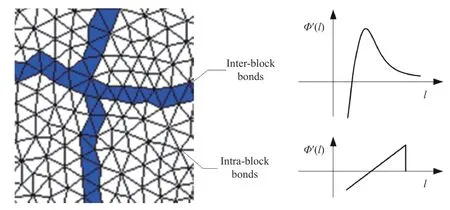
Fig. 3. Illustration of inter-block bonds and the intra-block bonds (the bonds covered by the colourful trace are the inter-block bonds whereas the bonds in a block are the intra-block bonds).
whereAis the initial stiffness of the inter-block bond andBis the relative characteristic bond length at which the bond force reaches the maximum. According to the diagram of this potential in Fig. 3, this potential can well describe the inter-block cohesion. When two blocks are compressed, the exponent stiffness can resist the embedment of blocks as far as possible.
The rock block itself is usually elastobrittle. To characterize the intact rock block, we use the following elastobrittle bond potential for the intra-block bonds. Its first derivative with respect to the bond length reads

whereαis the initial stiffness andβthe relative failure length of the intra-block bond. Ifβ=∞,Φ(l) becomes a linear elastic potential.
By considering both the inter-block and the intra-block bond potential, the DVIB should be able to simulate the multiscale rock fragmentation.
In the numerical implementation, we will firstly identify the inter-block bonds according to the coordinates of the Voronoi tessellation and the bond cells. The eventual outcoming equation of the discrete system has the form

where u is the nodal displacement vector of the discrete system;M and C are respectively the mass matrix and the damping matrix of the discrete system; F is the restoring force vector,which is usually an implicit function of the nonlinear system; R is the external force vector applied to the discrete system. To solve Eq. (9), we adopt the implicit time integration algorithm to compute the initial mechanical field while the explicit one to compute the dynamic fracturing process.
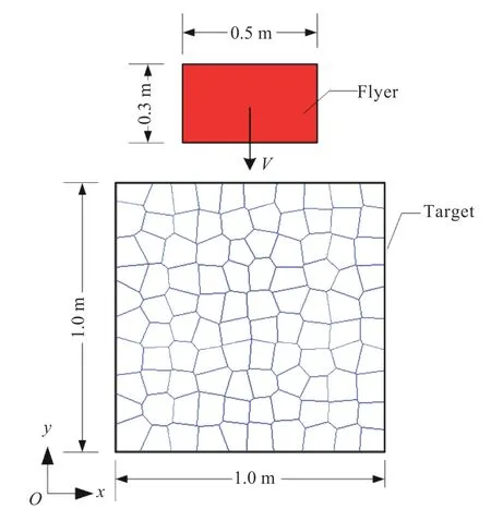
Fig. 4. Simulation object for impact.
Simulation examples
To examine the performance of the present method in rock fragmentation, we present two simulation examples in the following.
In the first example, we simulate an impact-induced fragmentation. The simulation object is a square target body impacted by a flyer, shown in Fig. 4. The target body is discretized into 100 Voronoi tessellations. The boundaries of the target body are traction- and restriction-free. The initial impact velocity of the flyer isV=25 m/s. The flyer is linear elastic withE=60.0 GPa and the densityρ=2400.0 kg/m3. The intrablock bond parameters areE=60.0 GPa ,β=1.002,ρ=2400.0 kg/m3. The inter-block bond parameters areE=40.0 GPa,B=1.0001. The explicit time integration algorithm is adopted with the time interval Δt=1.0×10⁻⁷s.
The simulated fragmentation process is shown in Fig. 5. It is seen that the target body is impacted into many blocks. It is noticed that some blocks near the impact surface are smashed.This indicates that this method can simulate both the inter-block and the intra-block fracturing process.
As a comparison, if we take the target block itself linear elastic by settingβ=∞in the intra-block bond potential (Eq. (8)), the simulation results are shown in Fig. 6. In the linear elastic intra-block bond case, only the inter-block fracturing process is reproduced. There are no intra-block fracture. In this simulation example, it also can be found that the DVIB can directly simulate the large rigid body rotation and movement of a block. This is very important for the rock fragmentation simulation.

Fig. 5. Simulated fragmentation process of rock under impact with elastobrittle taget blocks.

Fig. 6. Simulated fragmentation process of rock under impact with linear elastic starget blocks.
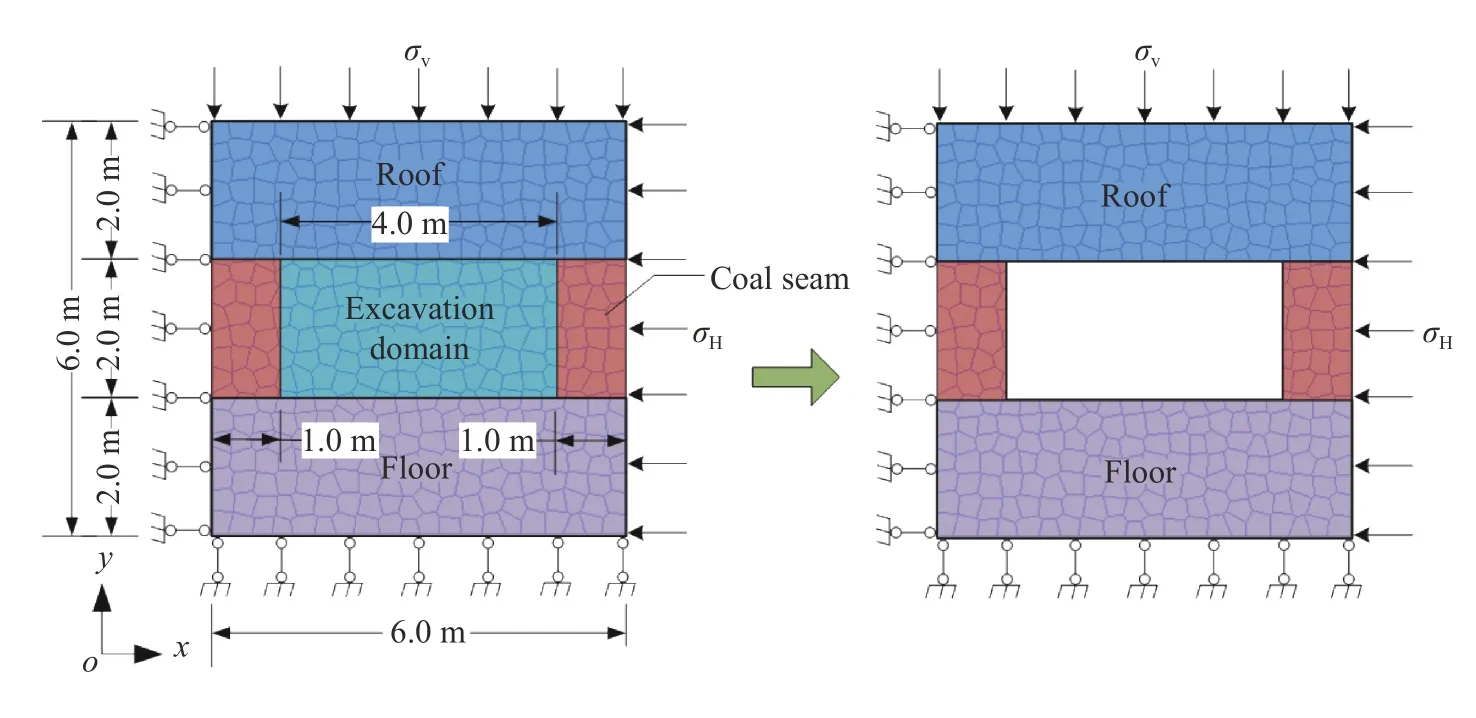
Fig. 7. Simulation object for coal seam excavation.
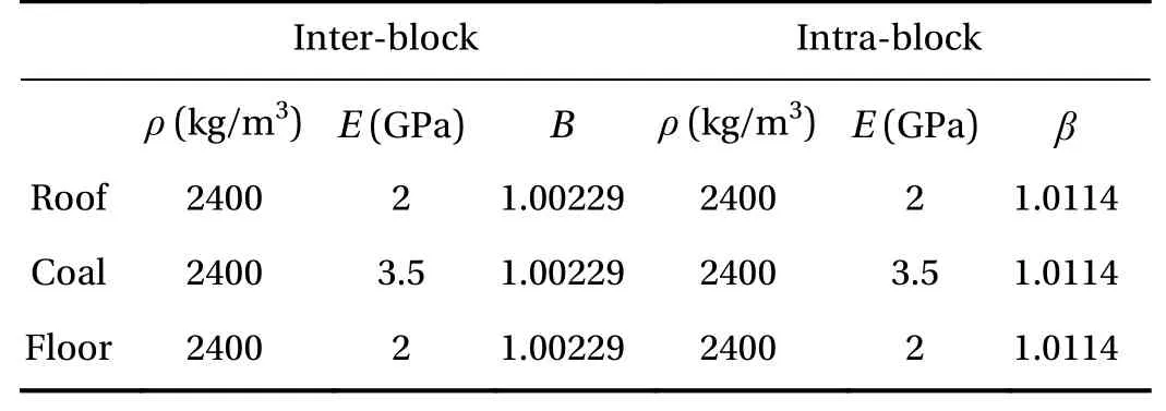
Table 1 Material parameters for tunnel collapse simulation
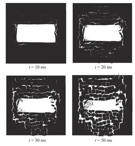
Fig. 8. Simulated coal seam tunnel collapse process after excavation with elastobrittle blocks.
In the second example, we simulate the tunnel collapse during coal seam excavation. The simulation object and the boundary conditions are shown in Fig. 7. It is composed of three zones,i.e., the roof, the coal seam and the floor zone. The left and lower boundaries are normally restricted. On the right and upper boundaries are applied the in-situ stresses. They areσH=20 MPa ,σV=15 MPa. Take gravity accelerationg=10 m/s2. The material parameters are listed in Table 1.
The interesting domain is discretized into 400 Voronoi tessellations. Firstly, the in-situ stress and gravity are slowly applied to the model, which is solved by the implicit time integration algorithm. Once the initial mechanical field is computed, the elements in the excavation domain are removed, shown in Fig. 7.After the excavation, the explicit time integration algorithm is adopted with the time interval Δt=1.0×10⁻⁶s. The simulation result is shown in Fig. 8. It is seen that the surrounding rock of the cavity begins to collapse due to the excavation. The surrounding rocks are fragmented into blocks and some blocks are smashed. This is consistent with the usual surrounding rock collapse of tunnel in the mining. If we do not consider the intrablock fracture by settingβ=∞in the intra-block bond potential (Eq. (8)), the simulation results are shown in Fig. 9. Compared Figs. 8 and 9, the collapse mode in Fig. 8 is much closer to the scenario of the coal tunnel collapse. So, consideration of the block smash is important for the rock fragmentation.
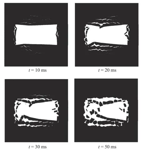
Fig. 9. Simulated coal seam tunnel collapse process after excavation with linear-elastic blocks.
The two examples demonstrate that the present method can simulate rock fragmentation. Both the inter-block and intrablock fracturing process can be well simulated. It provides a very simple and efficient method for the rock fragmentation simulation.
Acknowledgment
This work was supported by the National Natural Science Foundation of China (Grant 11772190), which is gratefully acknowledged.
杂志排行
Theoretical & Applied Mechanics Letters的其它文章
- A unidirectional SH wave transducer based on phase-controlled antiparallel thickness-shear (d15) piezoelectric strips
- A novel method for investigation of acoustic and elastic wave phenomena using numerical experiments
- A note on a family of proximal gradient methods for quasi-static incremental problems in elastoplastic analysis
- Dynamic mode decomposition and reconstruction of transient cavitating flows around a Clark-Y hydrofoil
- Numerical investigations to design a novel model based on the fifth order system of Emden-Fowler equations
- Ultrasound calibration with ladder phantom at multiple depths for breast biopsy navigation system
