Ultrasound calibration with ladder phantom at multiple depths for breast biopsy navigation system
2020-11-04JckritSuthkornNruchTniutchwootCholtipWirtkpn
Jckrit Suthkorn*, Nruch Tniutchwoot Choltip Wirtkpn
a Center for Biomedical and Robotics Technology (BART LAB) Department of Biomedical Engineering, Faculty of Engineering, Mahidol University, Salaya,Thailand
b Breast Diagnostic Center, Division of Diagnostic Radiology, Department of Radiology, Faculty of Medicine, Ramathibodi Hospital, Mahidol University,Bangkok, Thailand
Keywords: Ultrasound calibration system Ladder phantom Multi ultrasound depth Passive robotic needle holder
ABSTRACT Ultrasound guided breast biopsy navigation system with a graphical user interface and a passive robotic needle holder is developed to increase the performance and reliability of the radiologist.Ultrasound calibration and tool tip calibration are required before using the system. A ladder phantom is developed to be used for ultrasound calibration in real time system with only one ultrasound image required. The passive robotic needle holder structure results in an identity matrix for the makes the rotation matrix; therefore, only translation and scaling are required in the system. This method can be applied to multiple ultrasound depths, which has a relationship at each depth and a relationship to the ultrasound image on the display. The results show high accuracy (<1 mm.) and rapid calibration (5-10 minutes) which is suitable for a real time system like a breast biopsy navigation system based on tests with a breast phantom.
Breast biopsy is a procedure to obtain breast tissue, suspected to have cancerous, for examination. Medical modalities such as computed tomography (CT), magnetic resonance imaging(MRI) , 3D ultrasound, mammogram and 2D ultrasound, are applied to an image guided breast biopsy. Each has different types of techniques and gives various types of information. The conventional method for image guiding in breast biopsy is the 2D ultrasound image because it is inexpensive, there is no radiation,and it takes less time, has real time guidance and is more convenient for both patient and radiologist [1-3]. The patient lies down on a bed in supine position; the radiologist begins investigating an expected lesion and performs a breast biopsy using real time ultrasound image guidance [4, 5]. Even though ultrasound guided breast biopsy is a necessary procedure, needle guidance using a 2D image may also be a problem [3]. Many researchers, therefore, are working to develop a breast biopsy navigation system using different types of image modalities.
Ultrasound image-guided robotic breast biopsy was developed to localize the position of expected tissue and perform breast biopsies using the pendant patient breast position [3].However, this is not a conventional position for patients ultrasound guided breast biopsy. The aid for ultrasound guidance with static clip-on and couples rotary wheel needle guide device permits needle insertion using an ultrasound image but does not constrain needle motion within the ultrasound plane and is related to disposition of ultrasound image guidance [6]. Bluvol et al. [7] and our breast biopsy navigation system developed with the two planar linkage needle guidance for ultrasound guided breast biopsy. The needle insertion is overlaid on the ultrasound image to guide the radiologist. In Ref. [6], magnetic rotary sensors are used to localize the needle compare to the ultrasound transducer scanning surface.
Our present breast biopsy navigation system focuses on the procedure of coaxial needle insertion, the first procedure of breast biopsy, before using the biopsy needle to get multiple tissue samples. The system consists of a passive robotic needle holder and a graphical user interface with 2D ultrasound image guidance. The passive robotic needle holder aims to handle the coaxial needle’s alignment to be on the same alignment of ultrasound image using a planar robotic design. The coxial needle’s alignment and an insertion path between the target and entry point of insertion on the breast surface are displayed on the graphical user interface. This guidance can decrease tissue damage from multiple insertion and movement. An optical tracking device links all components. However, before starting the breast biopsy procedure, two procedures are required: tool tip calibration [8] and ultrasound calibration. The results from both of these methods are applied in the image guidance in the graphical user interface. The tool tip calibration procedure is used to find the tool tip position with respect to the marker that is attached to the needle, so the position of the needle tip is determined with respect to the world coordinates after utilizing the homogenous transformation.
The conceptual idea for ultrasound calibration procedure is similar to tool tip calibration, but is more complicated. Ultrasound calibration is needed to extract the information from 2D ultrasound image to 3D information, which assembles individual 2D ultrasound images into 3D volume and links position of surgical tools with respect to reconstructed volume. A tracking system, optical tracking or electromagnetic tracking, is needed to localize the position of the device and target in real world to link the information in the computer for calculation and guidance. Transformation matrices are needed to find the relationship of each matrix and unknown parameters, which will be determined by the calibration procedure [9]. The overall transformation of this method is shown in Fig. 1
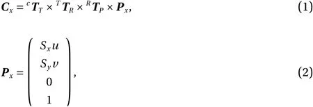
whereuandvare the column and row, respectively, of the pixel in the ultrasound image,SxandSyare scale factors with the unit mm/pixel, andCxis the pixel’s location in the coordinate system.
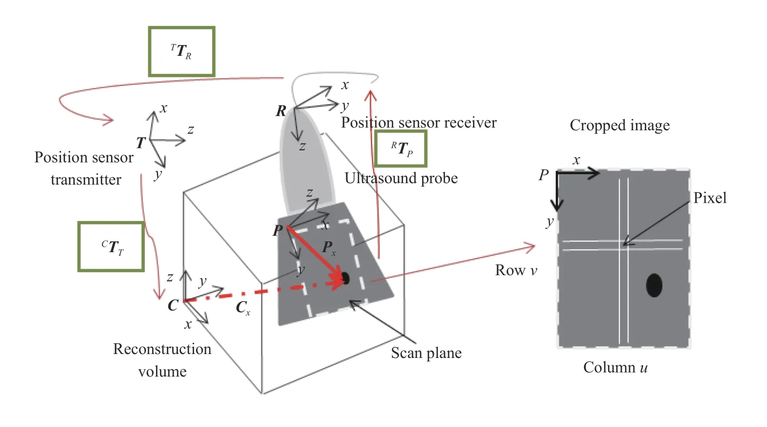
Fig. 1. Transformation between different coordinate systems.
The accuracy of the anatomical position depends on the calibration system [10], so there are many researches towards the development and investigation of various types of phantoms [11,12]. In Ref. [13] it classifies phantoms as follows: single point target and cross-wire phantoms [14], multiple point targets and cross-wire phantoms, 2D shape alignment phantoms, three-wire phantoms, fiducial phantoms, and wall phantoms. Not only do types of phantom affect the system accuracy but also closed form solutions or calibration methods are also important. Viswanathan et al. [15] utilize the closed form solution from two motions of the ultrasound transducer to decrease error when compared with traditional segmentation of points from ultrasound images.Moreover, some research [16] developed this system by applying image processing and a graphic user interface to automatically collect data and control a system. The researchers in Ref.[17] describe and summarize advantages and disadvantages for each type of phantom in terms of transducer type, ease of use,calibration reliability, accuracy and time. N-wire phantom calibration and tracked pointer are used to compare the consistency and accuracy of ultrasound calibration [18]. The result shows calibration using a tracked pointer has greater variance but better accuracy than N-wire phantoms. Tracked pointer calibration removes the source of multiple errors and is also more convenient in the ultrasound calibration procedure because no extra equipment is required. Even though there are many strategies for ultrasound calibration, there are some restrictions for each type that relate to ultrasound calibration in our breast biopsy navigation system. The Cambridge phantom is appropriate for a linear transducer and has high accuracy, but it takes time to finish and requires skill. N-based phantom, on the other hand, is the easiest to use and has rapid calibration. It is proper for a curvilinear transducer but has the worst accuracy result.
At our lab (BART LAB), an N-based phantom for ultrasound calibration algorithm [3, 16] with optical tracking system (Polaris Vicra, workspace 273 mm × 69 mm × 69 mm) was developed and tested. Details and procedures of this ultrasound calibration were explained in Ref. [16]. In this experiment, an ultrasound machine (IU 22, Philips) with 4 cm depth and linear transducer (L 12-5) were used for ultrasound calibration, and the result was integrated in the breast biopsy navigation system. The experiments were carried out using MATLAB program developed by BART LAB researcher, and the results are shown on Table 1.
From the table, it can be concluded that the results of each trial are different with numerous errors. Moreover, the number of images does not show any significance with respect to the accuracy. This method takes very long to collect and process images; however, the number of usable images is low when compared to the number of collected images. The results are applied to the breast biopsy navigation system developed in Visual Studio 2010 (WPF). After implementing the ultrasound calibration and tool tip calibration results into the breast biopsy navigation system, the system is tested with respect to its functionality with the phantom. A needle line, drawn from the position of the marker and tool tip, should be similar to that of the real needle as shown in the ultrasound image. Figure 2 shows an example of the integration system based on one result of the ultrasound image guided breast biopsy navigation system.
The simulated needle was shifted above the real needle and the length of simulation needle was shorter than the real needle.This result shows an error because of translation between the two systems. On the other hand, the rotation angle along theyaxis (perpendicular to the ultrasound image plane) with respect to the simulation needle corresponds to the real needle, which shows high accuracy along this axis. The rotation angle along thez(rotate) andx(front-back) axes should be zero because the needle lies on the ultrasound plane. Otherwise, the solution shows some error at both axes. When applied to other results of ultrasound calibration, the simulated needle also shift with respect to the real needle by varying distances.
These problems and errors are analyzed to improve ultrasound calibration results. The result from the tool tip calibration is one possible cause of error because tool tip calibration has a RMS error. This error is shown on the graphical user interface after finishing tool tip calibration process. Level of acceptable error varies on the user. However, the suggestion from the system is lower than one millimeter that will show green color on the light sign. Some such errors can result in the shifting of the simu-lation needle when compared to the real needle. On the other hand N-based phantom ultrasound calibration does not have consistency of results between the number of images and the system’s accuracy. Many ultrasound images are required, which leads to high time consumption.
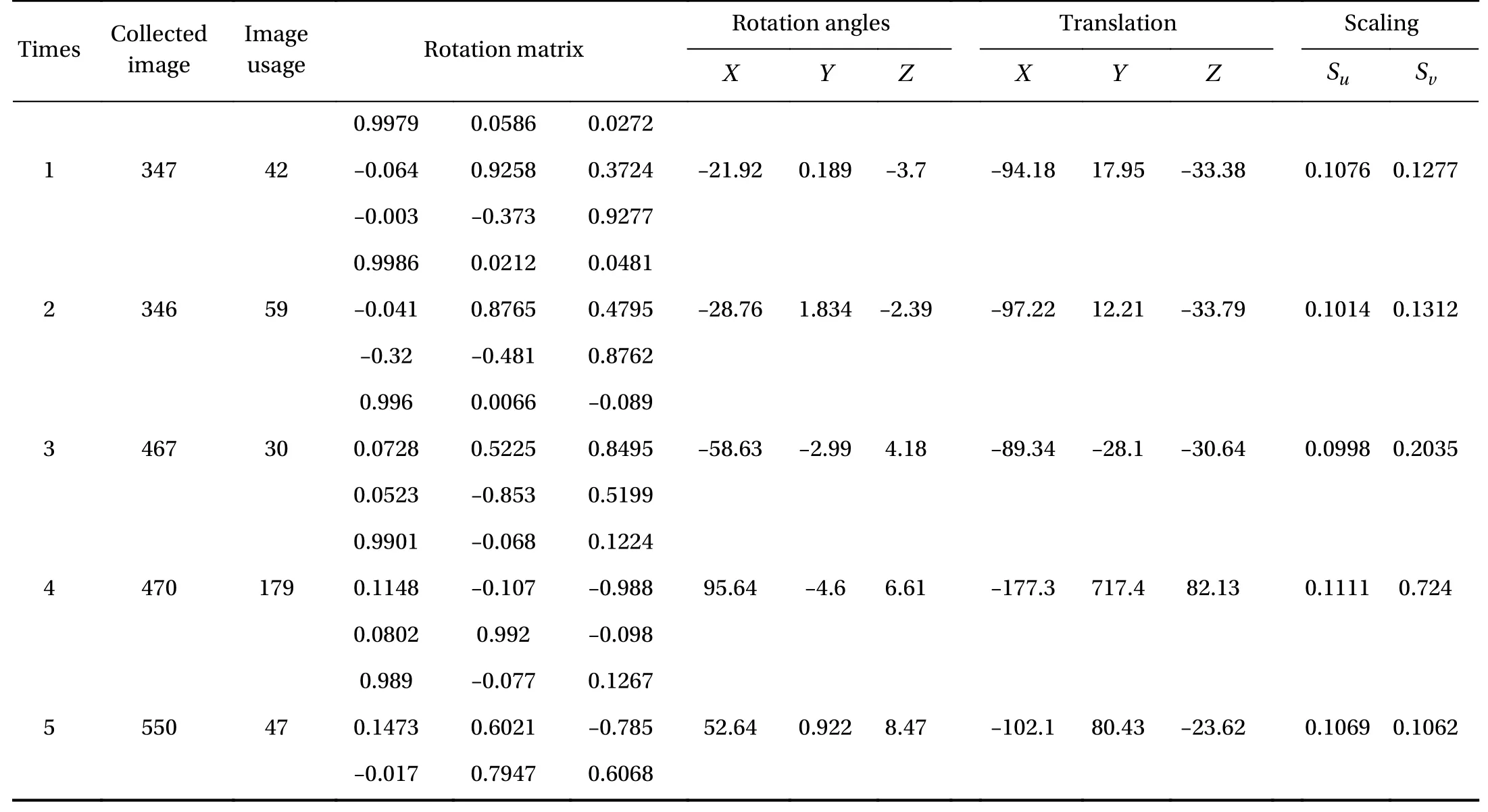
Table 1 Results of ultrasound calibration by N-based phantom in five times
This article presents the ultrasound calibration with a ladder phantom based on ideas of point phantom with stylus [19],multi-wedge phantom [20] and Cambridge phantom [21], which are easy to use, have rapid calibration, high accuracy and are appropriate for a linear transducer in a breast biopsy navigation system. The ladder phantom is called regarding the phantom design with 3 different levels of height. The edge of each ladder step presents the point on the ultrasound image that will be used for the ultrasound calibration. The results of ultrasound calibration from each ultrasound sound depth are discussed in the following section. N-based phantoms, developed by a BARTLAB members, are compared to the results and performance of the ladder phantom with respect to appropriation for breast biopsy navigation system. Moreover, the passive robotic needle holder and graphical user interface for ultrasound calibration and breast biopsy navigation system are discussed.
The passive robotic needle holder in Fig. 3 is designed and developed to control needle insertion alignment on the ultrasound plane. Two passive markers are attached to the passive robotic needle holder at a specific position. The first marker(passive marker 1 in Fig. 3) is assumed to be the world coordinates which are important for ultrasound calibration because information from an ultrasound image is related to this marker.The second marker (passiev marker 2 in Fig. 3) is used to localize needle position and is also important for tool tip calibration.The positions of the markers are designed to be parallel to the ultrasound transducer and ultrasound plane for easier implementation of the navigation system. Moreover, the component from the passive robotic needle holder (transducer attachment 2) is designed and developed to remain perpendicular to the ultrasound transducer of the ladder phantom.
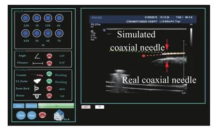
Fig. 2. Breast biopsy navigation system using the result of N-based phantom ultrasound calibration.
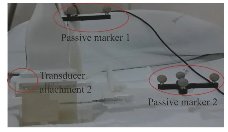
Fig. 3. The passive robotic needle holder for breast biopsy navigation system.
This ultrasound calibration procedure uses a passive robotic needle for assistance. The structure of the passive robotic needle holder allows the alignment of the passive marker and ultrasound image along the plane and in the same orientation.Moreover, the holder, attached to the clamp on the ultrasound transducer (transducer attachment 2), controls the ultrasound transducer position. The holder therefore maintains a perpendicular orientation with respect to the ladder phantom and aligns the ladder phantom along the ultrasound image plane.Therefore, the system is set to stay on the same orientation and it is implied that the orientation between the passive marker on the ultrasound transducer and the ultrasound image is an identity matrix. Only translation and scaling need to be determined for this system. The phantom’s position relates to the reference(the passive marker on the ultrasound transducer), which is determined using the pointer (coaxial needle after performing tool tip calibration) that helps avoid effects from tool tip calibration error. In the case of scaling, these parameters are found using the real distance (mm) and the distance in the ultrasound image(pixel) of the ladder’s corner at each step. The main purpose of this new procedure is rapid calibration, which is suitable for a linear transducer, with high calibration reliability and ease of use.
This new algorithm for ultrasound calibration based on a ladder phantom, a passive robotic needle holder and a coaxial needle is shown in Fig. 4 and is discussed in further detail in the scaling and translation sections. One ultrasound image is required to resolve the problem in this algorithm.
D1andD2are the distances between the corners of each ladder step in the real phantom (mm).SuandSvare the scaling factors in theZandXaxes, respectively. A limitation of these equations is the need for unequalD1andD2to avoid no solution

SuandSvcan be found using the Wronskian technique
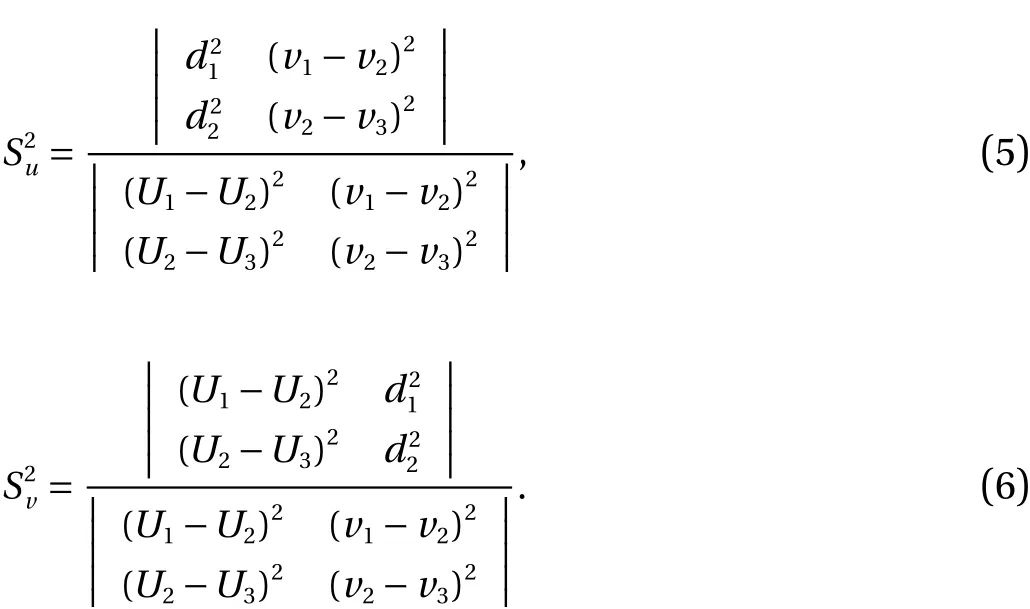
The reference coordinate is changed from the camera to the marker on the ultrasound transducer

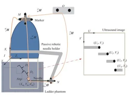
Fig. 4. Diagram of ultrasound calibration using a ladder phantom.

Then the origin of the ultrasound image (upper-left corner) is found by translating the needle tip’s position with respect to each axis along the ultrasound plane with appropriate scale as shown in the following equations

The ladder phantom in Fig. 5 made using transparent and white acrylic and is filled with gel candle. Gel candle is a good material for developing a phantom, especially for needle insertion with ultrasound image guidance, because sound penetrates this material and generates ultrasound images similar to those breast fats [22]. Moreover, this material is reusable, does not rot and self-repairs after needle insertion (usable for 1-2 days depending on the size of tract). The right side of the ladder phantom has a pore for needle insertion that controls the needle insertion to be a straight line. The ladder, made from white acrylic, is designed to stop the coaxial needle after insertion of 2 mm; the same thickness as the needle’s diameter.
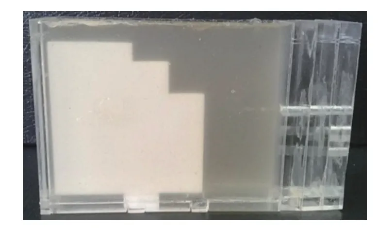
Fig. 5. Ladder phantom.
The ladder’s corners at each stage are required to calculate the distance to determine the image scale. Segmentation and localization are also required. There are two parts for image processing. (1) The first part is performed using real time images that go through basic image processing for guiding the user to choose an appropriate picture and find the ladder’s corners. (2)The second part is executed after the user captures an image from the real time image to fine tune the ladder corner and prepare the step for scaling and position calculations. Image processing is done in two parts because the frame rate decreases if many details of image processing that lead to delay time in imaging are completed before. Steps for finding the ladder’s corner at each stage are shown in the diagram below (Figs. 6 and 7).
An ultrasound image from video capture card (AVerTV Volar GO, supports video resolution of up to 720×576 pixels) is used to show images in real time; the proficiency of the real time image depends on the frame rate of each device. Each image from each frame is converted to bitmap index or binary image for image processing.
The image from the video capture card shows all information that is displayed on the ultrasound machine, but image processing is only performed on the ultrasound image area. Therefore, the image is cropped to keep the specific region of the ultrasound image; the coordinates of the area of interest represent(150, 100, 450, 375) the position ofX, position ofY, width and height.
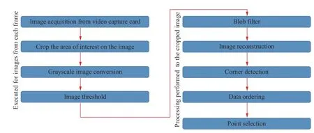
Fig. 6. Steps for finding the ladder’s corner.
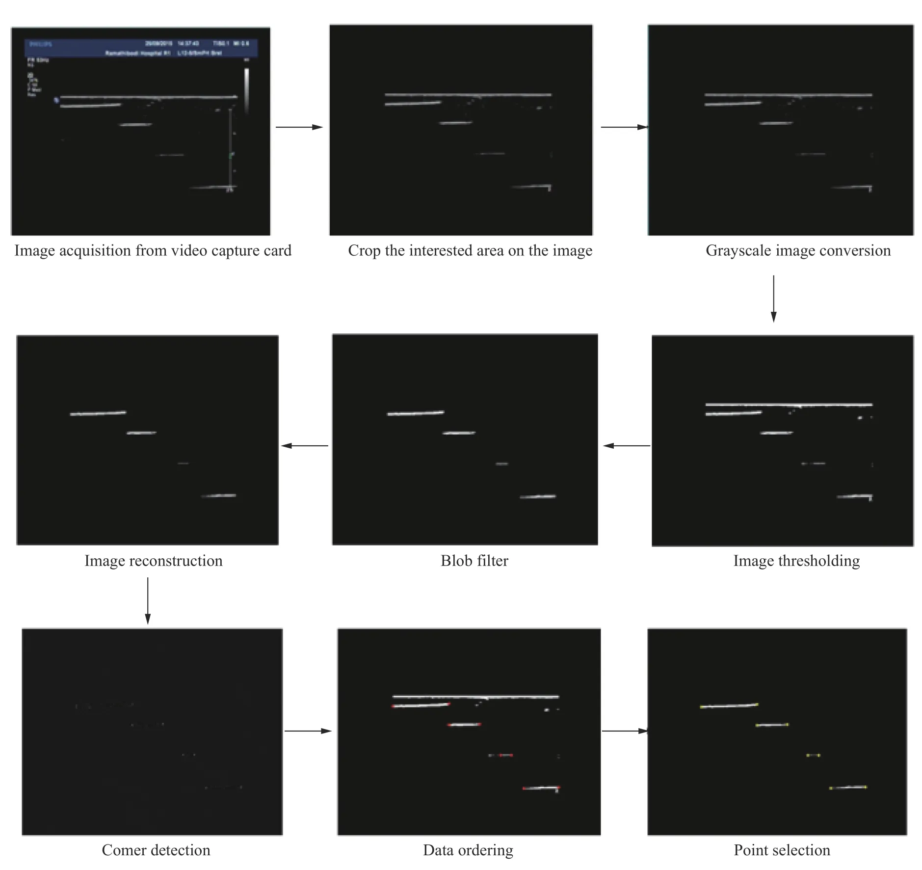
Fig. 7. Feature extraction from the ultrasound image to find the ladder’s corner.
All original color images are converted to gray scale images.Grayscale has less information per pixel. The grayscale intensity is stored as an 8-bit integer which gives 256 different shades of gray from black to white. The type of gray scale depends on the user’s setting for the ratio of red, green and blue components.
Image thresholding is a basic technique for image segmentation and is the most effective in images with high levels of contrast. This technique is applied to find the ladder’s steps and the inserted needle, which should be respectively by four lines deferent levels. The threshold number is set to a specific number;however. Contrast levels can be changed at the ultrasound machine for manual adaptation by the user. The image processing is adjusted until information is completed. The user clicks the capture button to capture the real-time image which is converted to a static image for the next step of image processing.
A blob filter is a filter of the size of area of interest and which rejects the noisy background. Only the ladder’s steps and the inserted needle identify the minimum and maximum height and width. The area that does not fit these conditions is discarded.
Four lines from thresholding and filter develop an incomplete image, so the reconstruction process is used to draw a straight line with white pixels and remove the unwanted area using black pixels. The first pixel is compared with the color of target pixel to surrounding pixels at the beginning. If there is white at the pixel position lower than the white line color, the pixel color is changed to black. This method eliminates the noise in and around the object of interest.
The intersection of two edges is a corner with different edge directions in the local neighborhood of the point. Harris corners detector is available as an open source file for developer programing. However, the results of the corner detection algorithm are multiple points at the corner of each step. The multiple points from a corner’s step are averaged to represent one point at the step’s corner.
Coordination of each point from the corner detection technique is not in sequence when collected in the program. This step rearranges the order of each point from the upper-left corner of the image to the lower-right corner of the image respectively to prepare for each point’s coordinates and compare each point in a local neighborhood of points.
The result after corner detection is incomplete; there are some points that appear at the center and between the left and right corners of the ladder’s step. Therefore, this process is used to check the point that represents the left and right corners of each step of the ladder. Minimum and maximum values ofXwith the sameYis found and identified to define the corners of each step. Yellow dots are drawn at these positions to show the result of corner detection, so the ultrasound image is changed from 8 bpp to 24 bpp.
The Philips iU22 xMATRIS ultrasound system with L 12-5 ultrasound transducer is used in this experiment. The output image of this modality is a digital to analog port that is the basic way to transfer a real time ultrasound image from the ultrasound machine to the guidance system. First, the ladder phantom for the ultrasound calibration (width 10 mm and heights 5 mm and 9 mm as shown in Fig. 8) is tested with a 4 cm depth of ultrasound image: The average depth of all ultrasound images. Ultrasound calibration with ladder phantom the, is tested at 2.5 cm, 3 cm, 3.5 cm, 4 cm, 4.5 cm, 5 cm, 6 cm, and 7 cm.
An optical tracking device, passive markers, ultrasound machine, passive robotic needle holder and ladder phantom are set up as shown in Fig. 8. The user has to check the tracking workspace before capturing an ultrasound image and starting image processing.
Using the algorithm discussed above, only one ultrasound image is needed to perform calibration. After completing calibration, the data is applied to the breast biopsy procedure. Figure 9 shows an example of the result after integrating tool tip calibration and ultrasound calibration in the breast biopsy navigation system at 4 cm depth from different positions. The simulated needle and real needle lie along the needle insertion path and rotate with the same orientation. This therefore supports the user of the ultrasound calibration algorithm for a breast biopsy navigation system.
The 35-ultrasound images were collected to test the repeatability of the translation and scaling determination. Tables 2 and 3 show the example results from 10 example experiments and the average and standard deviation of ultrasound calibration from 35 ultrasound images.
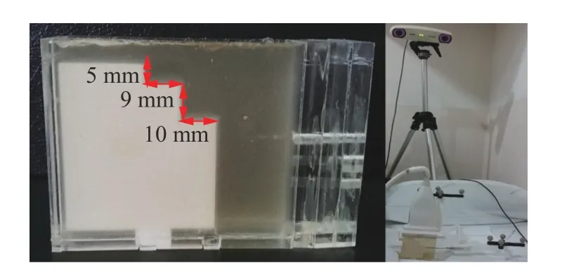
Fig. 8. Ladder phantom for ultrasound calibration of 4 cm depth and system set up for ultrasound calibration.

Fig. 9. Example result of an integrated breast biopsy system.
The results show high repeatability in scaling with low standard deviation results (< 0.01). The translations alongX,Y, andZaxes demonstrate low standard deviation (< 1). The diameter of the coaxial needle is 2 mm, therefore, the acceptable error is lower than 1 mm from the needle center. The results show shifting of less than 1 mm, therefore this method is suitable for ultrasound calibration. Moreover, after applying every result from the ultrasound calibration at each value, these results develop a simulated needle that lies along the path of the original needle.
The number of ultrasound image used in the calibration is not the main factor for high accuracy of the ultrasound calibration. One ultrasound image is enough for results similar to many ultrasound images. Low standard deviations of each result means the results are very close to each other. However, the most important factor for high accuracy in this method is the image proficiency for image processing, which is decided by a human investigator/researcher. Moreover, the ultrasound transducer position, passive marker and ladder phantom have to be at the right position.
The results of ultrasound calibration from 4 cm. depth cannot be used for other depths because the position of the ultrasound image that is displayed on the graphical user interface changes with respect to the ultrasound depth. Therefore, ultrasound calibration was performed at 2.5 cm, 3 cm, 3.5 cm, 4 cm,4.5 cm, 5 cm, 6 cm, and 7 cm depths to find the relationship between each ultrasound depth. The 15 images from different ultrasound depths were collected to find the relationship between each ultrasound image in scaling and translation results. Table 4 shows an example set of results at each depth.
Translation along theXaxis at each depth is a number similar to that along theYaxis, but translation along theZaxis was almost the same at depths of 2.5, 3, 3.5 and 4 cm. Scaling alsoshows similar numbers at depths of 2.5, 3, 3.5 and 4 cm and increased step by step at 4.5, 5, 6 and 7 cm depths. This changing shows a relationship when displayed on the ultrasound machine. The width of the ultrasound image is gradually decrease with a constant height when increasing the depths after 4 cm depth. Also, the height of the ultrasound image gradually decreases with constant width when decreasing the depths after 4 cm. Tables 5 and 6 show averages and standard deviations of ultrasound calibration results with respect to the translation and scaling from 20 ultrasound images.
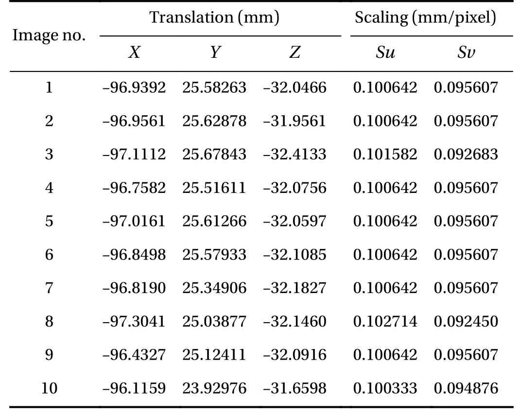
Table 2 Result of ultrasound calibration from 10 ultrasound images

Table 3 Average and standard deviation of ultrasound calibration from 35 ultrasound images
Each ultrasound depth result shows high repeatability for translation and scaling with a small standard deviation and average results at each depth similar to the result from one ultrasound image. This result implies that one ultrasound image is sufficient for ultrasound calibration at each depth as mentioned for 4 cm depth results. However, the relationship between the different depths cannot be determined as a mathematical equation, so ultrasound calibration is performed at every depth. The time to finish an ultrasound calibration at one depth is less than 30 seconds depending on the user; even if 8 trials of ultrasound calibration (8 ultrasound depths) are required, the time to finish the ultrasound calibration process is still comparably low.
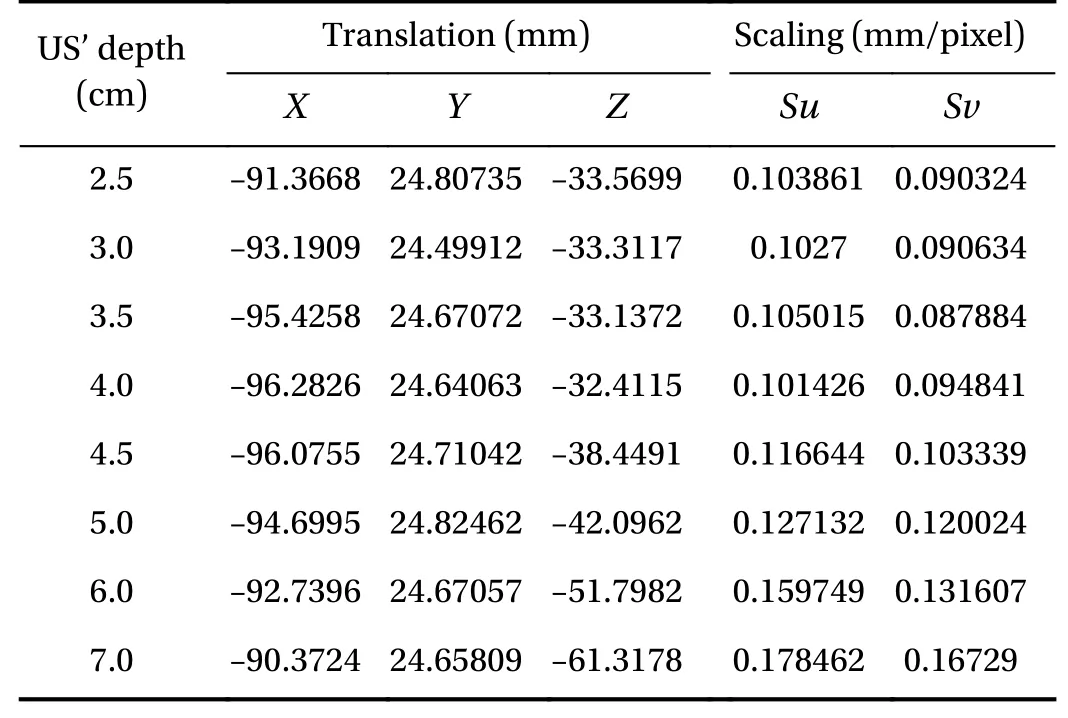
Table 4 Example of translation and scaling at different ultrasound image (US) depth from one set
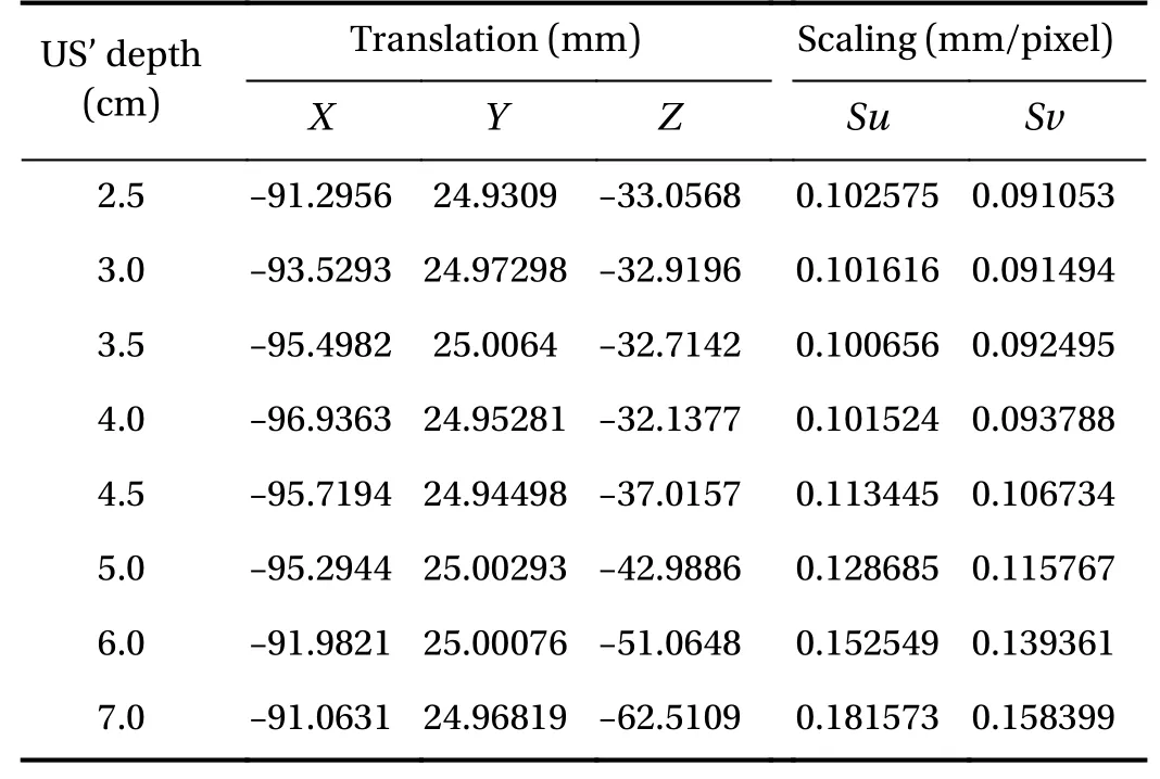
Table 5 Averages of ultrasound calibration from 20 ultrasound images
The US cal icon on the first page helps the program links to the ultrasound calibration page as shown in Fig. 10. The graphical user interface for the ultrasound calibration system consists of five parts: instruction for ultrasound calibration procedure, ultrasound image in real-time, results after image processing in image capture, ultrasound depth, and results of the ultrasound calibration.
This part consists of Start, Stop, Apply and Reset buttons. The Start and Stop buttons are used to control ultrasound machine.The Apply button records the ultrasound calibration’s result to the system. The Reset button deletes the previous value and recalibrate the device does the ultrasound calibration. The marker status alerts the user if the tools go outside the camera’s workspace. The progress bar shows the wait time for the camera connection. The Back button returns the user to the main page.
The ultrasound image from the ultrasound machine is displayed in this part of the graphical user interface (GUI) after transient the threshold image in real-time. The user can adjust the image with adjustment buttons on the ultrasound machine.Therefore, noise and speckle on the ultrasound image is filtered.When the information on the ultrasound image looks clear, the user clicks, Capture, to localize the ladder’s corner at each step and the needle tip’s positions.
Yellow dots represent a step’s corner detection and the needle tip position, consisting of 8 points. The number of yellow dots is shown on number of edge points. If the result of detec-tion is suitable for calculation, the process button will be ticked to find the translation and scaling of the ultrasound image. If the information is incomplete (such as wrong number of yellow dots), the caution will appear. A new image will be captured to restart all processes.
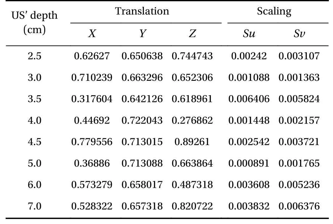
Table 6 Standard deviation of ultrasound calibration from 20 ultrasound images
Results are collected at a specific depth of the ultrasound calibration relates to depth choice. Therefore, the ultrasound calibration has to be done 8 times in different ultrasound depths to collect data at every level.
Position and scaling of ultrasound image are displayed in this part. If the result is unacceptable or incorrect, the capture button is pressed to start the image processing with a new image.
The breast phantom in Fig. 11a, using gel candle, is used to test the system’s accuracy. A plastic ball with 30 mm diameter is assumed as a breast lesion. Figure 11b shows the result of the ultrasound calibration integrated with the breast biopsy navigation system, which calculates the same path for the needle line and the real needle.
The N-based phantom requires many ultrasound images for highly accurate high accuracy of results. The ladder phantom requires only one ultrasound image.
The time to set-up, collect data and calculation of N-based phantom is longer than for the ladder phantom, because of all the processes and the number of ultrasound images required.Ultrasound calibration with N-based phantom can be completed in around 15-20 minutes, and ultrasound calibration with a ladder phantom takes around 5-10 minutes, which is different depending on user’s experience.
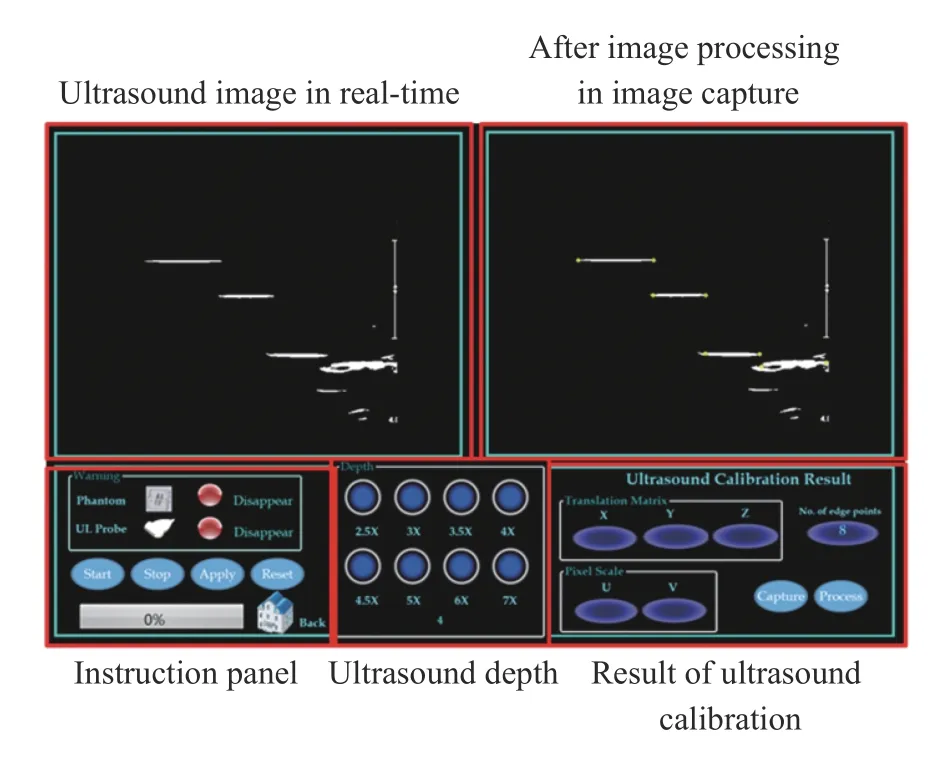
Fig. 10. Graphical user interface for the ultrasound calibration procedure.
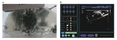
Fig. 11. Result of the ultrasound calibration integrated with the breast biopsy navigation system a the real breast phantom with breast lesions and b the guidance image in the GUI of the breast biopsy navigation system.
The ultrasound calibration of the ladder phantom shows high accuracy when compared to an N-based phantom in the results of a breast biopsy navigation system. The needle line usually shifts above or under a real needle approximately 10-15 mm when using the results from the N-based phantom. Conversely,the needle line lies on the real needle on the ultrasound image when using the ladder phantom for the ultrasound calibration.However, the diameter of a coaxial needle is 2 mm, so the acceptable error from ultrasound calibration should be less than 1 mm.
Ultrasound calibration using a ladder phantom and a passive robotic needle holder to control the transducer position and alignment has been designed for use in a breast biopsy navigation system. Only one image at each depth is required to find the position and scaling of the ultrasound at each depth with high accuracy and rapid calibration, which is suitable for a real-time system. The phantom position can be determined using the coaxial needle (after doing tool tip calibration), which reduces the errors associated with the phantom design. Moreover, the static structure of the passive robotic needle holder helps control the repeatability of ultrasound the ultrasound calibration;ultrasound calibration procedure is not needed every time before starting the breast biopsy navigation system. However, this experiment has high accuracy for the linear transducer, but not for a curvilinear transducer. In the future, the authors aim to develop the relationship of the ultrasound calibration at each depth by analyzing and determining the mathematical equation to develop a more convenient ultrasound calibration for any ultrasound depth.
Acknowledgement
This research was funded by the Computer-Integrated Intelligent Medical System Project under the National Research University Grant through Mahidol University. Another fund resource is the Integration of Surgical Navigation and Surgical Robotics for Breast Biopsy in Breast Cancer using Mammogram and ultrasound Images on Breast Mathematical Model Project under the Government Research Budget through Mahidol University (Grant 111-2558). N. Tanaiutchawoot would like to thank Ramathibodi hospital staff and radiologist to give me a lot of knowledge and recommendation to develop this system. Another group N. Tanaiutchawoot would like to thank is BARTLAB members who give me many knowledge in mechanical design,programming and statistical analysis.
杂志排行
Theoretical & Applied Mechanics Letters的其它文章
- A unidirectional SH wave transducer based on phase-controlled antiparallel thickness-shear (d15) piezoelectric strips
- A novel method for investigation of acoustic and elastic wave phenomena using numerical experiments
- A note on a family of proximal gradient methods for quasi-static incremental problems in elastoplastic analysis
- Modeling rock fragmentation by coupling Voronoi diagram and discretized virtual internal bond
- Dynamic mode decomposition and reconstruction of transient cavitating flows around a Clark-Y hydrofoil
- Numerical investigations to design a novel model based on the fifth order system of Emden-Fowler equations
