On the mechanism by which nose bluntness suppresses second-mode instability
2020-08-10ArmaniBatistaArhamAminKhanJosephKuehl
Armani Batista, Arham Amin Khan, Joseph Kuehl
Department of Mechanical Engineering, University of Delaware, Newark, Delaware 19716, USA
Keywords:Second mode instability Hypersonics boundary layer Blunt body paradox Entropy layer
ABSTRACT A physical mechanism by which nose bluntness suppresses second-mode instability is proposed.Considered are 7 degree half-angle straight cones with nose bluntness radii of 0.15 mm, 3.556 mm,5 mm, 9.525 mm, 12.7 mm and 25.4 mm at tunnel conditions relevant to the AFOSR-Notre Dame Large Mach 6 Quiet Tunnel. It is shown that second-mode suppression is achieved via entropy layer modulation of the basic state density gradient. A weakening of the density gradient disrupts the acoustic resonance necessary to sustain second-mode growth. These results are consistent with the thermoacoustic interpretation which posits that second-mode instability can be modeled as thermoacoustic resonance of acoustic energy trapped within an acoustic impedance well.Furthermore, the generalized inflection point criterion of Lees and Lin is applied to develop a criterion for the existence of second-mode instability based on the strength of the basic state density gradient.
©2020 The Authors. Published by Elsevier Ltd on behalf of The Chinese Society of Theoretical and Applied Mechanics. This is an open access article under the CC BY-NC-ND license(http://creativecommons.org/licenses/by-nc-nd/4.0/).
Nomenclature
AWave amplitude
cpSpecific heat at constant pressure
cvSpecific heat at constant volume
MMach number
mMass
PPressure (Pa)
RnNose radius (mm) or (in)
ReReynolds number
sEntropy (J/K)
TTemperature (K)
tTime (s)
UStreamwise velocity (m/s)
uStreamwise velocity (m/s)
vWall-normal velocity (m/s)
WWeight function
wAzimuthal velocity (m/s)
xStreamwise direction (m)
yWall-normal direction (m)
zAzimuthal direction (m)
α Streamwise wave number
β Crossflow wave number
γ Specific heat ratio
ν Kinematic viscosity (m2/s)
ρ Density (kg/m3)
Σ Summation
σ Bandwidth deviation
Φ Generic wave variable
φ Generic flow variable
ω Frequency (kHz)
′Disturbance quantity or wall-normal derivative (context provided by text)
¯ Basic state identifier or slow variable assumption (context provided by text)
ˆ Generalized inflection point criterion identifier (context provided by text)
Subscript
0 Stagnation quantity
eBoundary layer edge quantity
iVariable number
kIndex number
∞ Freestream quantity
Controlled and sustained hypersonic flight remains an open problem and a national priority in many countries. Several gaps in fundamental knowledge exist which must be addressed before sustained hypersonic flight operations can be achieved that analog the commercial aviation industry or meet the requirements of civil defense [1, 2]. One important open question is a fundamental understanding of the physical mechanisms responsible for the transition from a laminar to turbulent boundary layer (the "transition" problem). At high Mach number (i.e.10 <M<50, relevant to atmospheric re-entry) these gaps in knowledge correspond to aerothermodynamic heating (i.e.chemical non-equilibrium, ablation, etc.). Even at lower hypersonic Mach numbers (3 <M<10), where the compressible Navier-Stokes equations and ideal gas assumption hold, these gaps in knowledge persist [1, 3]. It is this "lower" hypersonic Mach number range which will be the focus of this manuscript.
The effect of transition on aerothermal heating of a vehicle is straightforward; turbulent boundary layers experience about 5-10 times greater heating than equivalent laminar boundary layers [4]. Thus, delaying the transition from laminar to turbulent flow over a vehicle results in significant reduction in thermal load. This allows for more efficient vehicle design by reducing the amount of heat shield required. The effect of transition on ballistic trajectory accuracy is slightly more subtle. Consider a laminar boundary layer over a streamlined vehicle. As laminar boundary layers result in less skin-friction drag than turbulent boundary layers, if the vehicle experiences asymmetric transition (i.e., one side of the vehicle is laminar and the other side is turbulent), an asymmetric drag will result. Due to their streamline nature, hypersonic vehicles have limited control surface functionality. Such asymmetric drag can overwhelm vehicle control capability resulting in loss of vehicle flight stability and catastrophic vehicle failure [2, 5]. In addition, transitional flow over a control surface may also lead to loss of flight stability and catastrophic vehicle failure. Thus, a fundamental understanding of hypersonic boundary layer transition physics is crucial to next generation vehicle development.
One of the many interesting open questions concerning hypersonic boundary layer transition is the so-called "blunt body paradox". That is, in second-mode dominated transitional boundary layers (such as blunt straight cones), the laminar-toturbulent transition is delayed with increasing nose bluntness.However, there exists a critical nose bluntness at which the transition front will jump forward (upstream). The cause of this"upstream jump" is unknown and is referred to as the "blunt body paradox" [6]. Much effort has focused on resolution of this paradox, with the bulk of the work revolving around the socalled transient growth mechanisms, i.e. non-modal instability[7, 8]. While these dynamics have been well documented both numerically and experimentally [9, 10] the underlying physical mechanisms remain elusive (for both transition delay and upstream jump). The computational study of Tufts and Kimmel[11] verified the hypothesis of Juliano et al. [12] that the delay in transition (downstream movement of the transition front) is associated with the suppression of second-mode growth and not associated with larger transitional N-factors. Tufts and Kimmel[11] also documented the relationship between the entropy layer swallowing length [13] and second-mode growth suppression.Meaning, second-mode growth was found to be suppressed within the entropy layer (upstream of the entropy layer swallowing length) while beyond the entropy layer (downstream of entropy layer swallowing length) second-mode growth was found to be unaffected by the bluntness. Additionally, computational stability results from Jewell and Kimmel [14] showed that Nfactors decrease as nose bluntness increases. Thus, it seems obvious that second-mode growth suppression is caused by entropy layer modifications to the boundary layer. However, the physical mechanism by which such suppression occurs is not yet fully understood. The purpose of this manuscript is to address the physical mechanism by which nose bluntness alters secondmode growth. Before attempting to understand the "blunt body paradox", it is logical to first understand the physical mechanisms responsible for second-mode growth suppression due to nose bluntness.
Recently, Kuehl [15] proposed that second-mode instabilities behave as resonant thermoacoustic waves trapped in an acoustic impedance well. Figure 1 illustrates such trapping. Several phases of wall normal velocity disturbance (v′, red line) and pressure disturbance (p′, blue line) are shown for a secondmode oscillation within an acoustic impedance well (black curve), where homogeneous acoustic impedance is given as the square root of basic state density fieldNote, that the acoustic impedance in the figure has been shifted horizontally for clarity. It is clearly seen that the second-mode wave is contained within the acoustic impedance well formed between the density gradient and the vehicle wall. Further, by adopting a Lagrangian frame of reference for the inviscid acoustic energy equation,Kuehl [15] was able to show (with the rather limiting inviscid and 1D restrictions) that this resonance is driven by thermoacoustic Reynolds stresses where " 〈〉"represent cycle averaging, over-bar indicates basic state quantities, prime indicates disturbance quantities, andyis the wall normal direction. Here this new theory will be applied to the blunt nose problem to understand the physical mechanism by which nose bluntness is able to suppress second-mode growth.
Following the protocol established by Stetson [13] (and later Marineau et al. [9]), seven-degree half-angle, straight cone geometries of different nose bluntnesses are considered. The cone walls were modeled as a single, smooth body. The nominally sharp nose cone has a length along its axis of 1.6 m, which is used as the reference length for the remaining cones. With a seven-degree half-angle, the base radius is 196.45 mm which was held constant in each case. The spherical nose radii considered are: 0.15 mm (sharp), 3.556 mm, 5 mm, 9.525 mm, 12.7 mm, and 25.4 mm (Fig. 2). Steady, laminar basic state solutions were obtained with US3D. US3D is a CFD software package specifically designed for high-speed flows which uses the finite volume method to solve the compressible Navier-Stokes equations.Moreover, US3D incorporates high order solving schemes, various viscosity and gas properties, and other physical aspects which help to create high accuracy solutions [16-18].

Fig. 1. An example of second-mode wall normal velocity (v ′ , red) and pressure ( p′, blue) disturbances at different phases of oscillation. Modes are calculated at 1.1 m from the sharp nose tip, where the most unstable second-mode is approximately 130 kHz. Superimposed on the background is the acoustic impedance ( in black) which has been shifted for clarity. v′ and p′ are non-dimensionalized in the standard way and normalized by the maximum of the absolute value of T′ . None shifted profiles can be seen in Fig. 5.
Our hypersonic CFD process consists of creating the geometry in Solidworks, meshing in Pointwise, running US3D to produce the steady state solutions (basic states), and visualizing the flow field in Tecplot. The wall normal data of the basic state was extracted using a combination of Tecplot and in-house developed scripts. The mesh dimensions are as follows, 1600 streamwise points, one degree rotation in the azimuthal direction (corresponds to one cell width), and test-driven convergence to determined the number of wall normal points (shown in Table 1). The flow conditions are representative of the AFOSRNotre Dame Large Mach 6 Quiet Tunnel conditions at a unit Reynolds number of 1.1×10⁷[19].
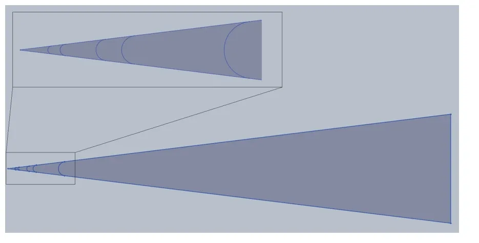
Fig. 2. Schematic of cone geometries illustrating nose bluntness variations.
In US3D, the inputs and boundary conditions for the freestream and the isothermal wall were calculated by using the isentropic flow relations and unit Reynolds number. The inflow conditions and wall temperature are listed in Table 2. The other boundary conditions were defined as an outflow at the downstream end of the domain, and symmetry conditions on both azimuthal sides. Additional settings included non-reacting, laminar, viscous flow. Using CFL ramping, the calculation was run until converged, and a steady state solution was reached [20].Figure 3 shows Mach contour plots of the flow field for each nose bluntness. In each plot, a normal shock is present at the nose ofeach cone which shifts to an oblique shock sufficiently downstream of the nose region.

Table 1 Test models
The JoHKeR parabolized stability equations (PSE) package[21, 22] was developed in collaboration with Dr. Helen Reed at Texas A&M as part of the efforts of the National Center for Hypersonic Laminar-Turbulent Transition Research. The code employs a Quasi-3D, compressible, ideal gas, primitive variable formulation; that is, it marches disturbances along a predefined path with the assumption of uniformity in the perpendicular direction. The package consists of linear stability theory (LST), linear parabolized stability equations (LPSE) and Nonlinear Parabolized Stability Equations (NPSE) codes. These codes has been extensively validated against experimental [22-25] and numerical [20, 25-28] datasets. A unique feature of JoHKeR is that it employs a nonlinear wave packet formulation for NPSE implementation which allows for the modeling of finite bandwidth disturb-ances [22, 29] and thus accounts for spectral broadening and low-frequency content generation [22, 30] which is important for accurate prediction of nonlinear energy exchange [31].
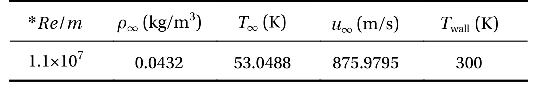
Table 2 Test conditions
Linear stability theory. LST considers a steady basic flow state, determined from separate CFD simulations, and solves the disturbance equation (which follows from substitution of Eq. (1)into the Navier-Stokes equations) assuming linear, parallel flow.The disturbance is assumed to be of the form indicated by Eq.(2), substitution of which into the disturbance equations leads to the generalized eigenvalue problem with α and ω being the streamwise wave number and the frequency respectively. The resulting eigenvalues are used to determine instability and the corresponding eigenvector represent the shape of the disturbance in the wall normal direction

Parabolized stability equations. Originally identified by Herbert and Bertolotti [32], during a critical review of Gaster's [33] early nonparallel work, the parabolized stability equations have been developed as an efficient and powerful tool for studying the stability of advection-dominated laminar flows. Excellent introductions to the PSE method and summary of its early development were provided by Herbert [34, 35]. During the early stages of both linear and nonlinear development of this technique, much was established related to basic marching procedures, curvature, normalization conditions, and numerical stability of the method itself [36-40].
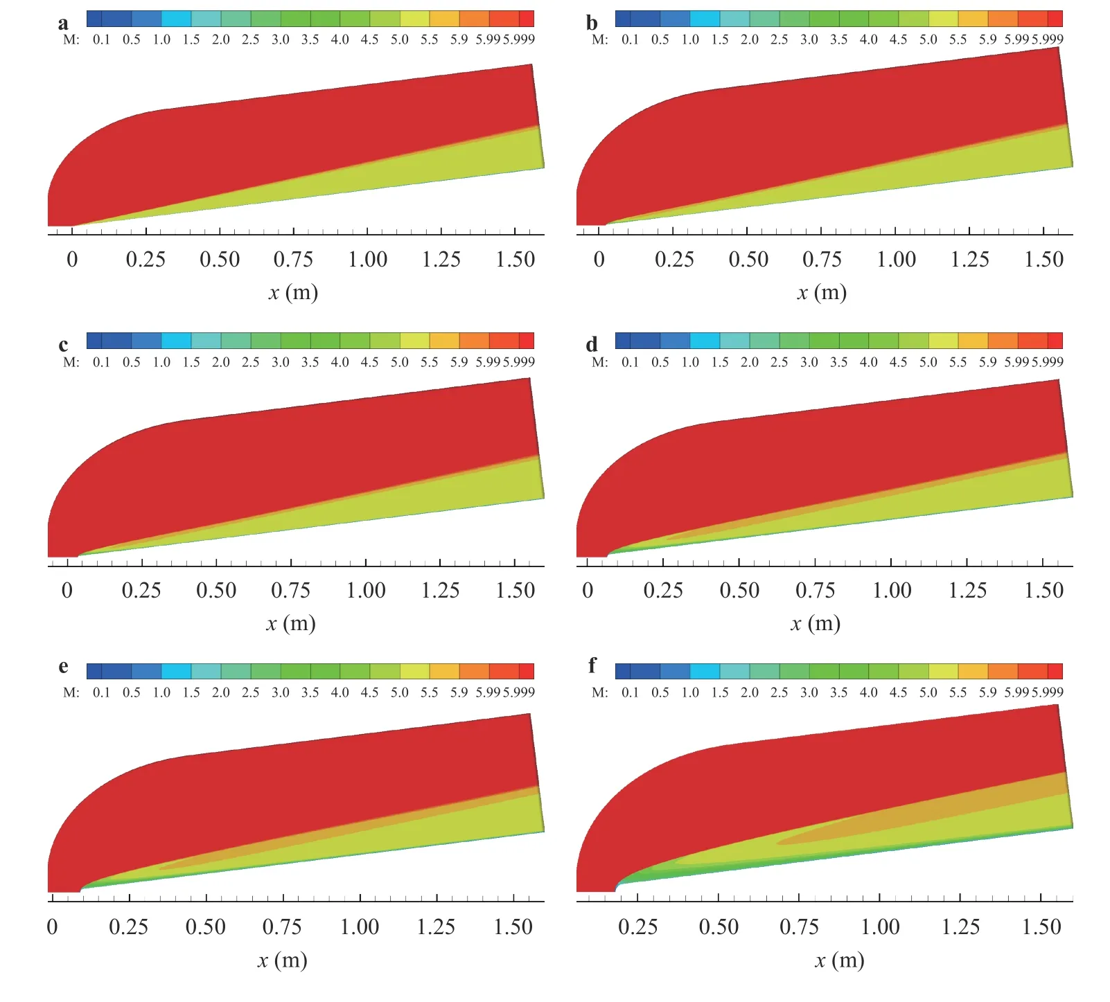
Fig. 3. Mach contours for a nose, b 3.556 mm nose, c 5 mm nose, d 9.525 mm nose, e 12.7 mm nose, and f 25.4 mm nose.
In a relatively short time, the field rapidly expanded to include complex geometries, compressible flow, and finite-rate thermodynamics [21, 24, 40-50].
PSE is similar to the Fourier/Laplace transform in that it considers an initial-value problem. However, the slowly varying basic state assumption is made in the streamwise direction and a slow variableis introduced. Ultimately, disturbances are assumed of the form
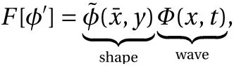
where the wave part satisfies

whereRe=Ueδr/νeis a Reynolds number based on characteristic values of edge velocity(Ue),edge kinematic viscosity( νe),and reference boundary-layer length scale( δr).Thus, PSE considers disturbances of the form
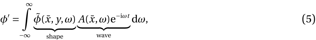
It is found that the second spatial derivativeis of highest order and a perturbation expansion may be consistently truncated resulting in the neglect of this term. This leaves the disturbance equation nearly parabolized [39], and an efficient marching solution may be sought. JoKHeR implements a wave packet formulation [22] which appears to better represent energy transfer between modes in a nonlinear calculation.Ultimately, in the Quasi-3D formulation, the disturbance is discretely represented asand a frequency content for each mode is assumed of the formWith bandwidth of the harmonics obeyingand harmonic balancing is used to calculate nonlinear interactions. This representation of spectral energy appears to be crucial for modeling the spectral broadening seen in experiments. Note, all perturbation quantities presented in this manuscript are nondimensionalized by their respective edge quantities and pressure byTheir amplitudes are normalized such that the temperature perturbations maximum amplitude is unity.
As discussed above, it has been well established that the presence of a strong entropy layer suppresses second-mode growth. In Fig. 4, the entropy layer for each case can be seen and it is clear that little or no entropy layer is present for the sharpest-nose cases (0.15 mm), a small entropy layer is formed for the 3.556 mm case that is swallowed after 0.3 m, a slightly stronger entropy layer is formed for the 5 mm nose bluntness that is swallowed around 0.5 m, a robust entropy layer is formed for the 9.525 mm case that is swallowed near 1.1 m, and for the two bluntest-cases (12.7 mm and 25.4 mm) a strong entropy layer is not swallowed on the body for the cone. These results help explain LPSE calculations (Fig. 5, left column). In those regions with no (or a weak) entropy layer, the boundary layer is susceptible to second-mode instability. In those regions with a robust entropy layer, second-mode instability is significantly diminished or not present at all. Our calculations are consistent with the expectation that modal growth is not present within the entropy layer, though an exhaustive search of oblique modes was not conducted. This is consistent with the idea that some form of non-modal growth is responsible for the blunt body paradox.
The thermoacoustic interpretation of second-mode dynamics [15] posits that second-modes behave as thermoacoustic resonators in a thermoacoustic impedance well. The acoustic impedance of a homogenous medium is proportional to the square root of the basic state densityFigure 5 (right column)shows profiles of acoustic impedance at different locations along the cone for the various nose bluntnesses considered. For the sharpest-nose case (0.15 mm), we observe a well-defined acoustic impedance well with a sharp gradient in impedance (density)at all locations along the cone. Comparing the impedance profiles with the stability calculations (Fig. 5, left column), we notice that when moving downstream the acoustic impedance well widens (peak density gradient is further from the wall) and correspondingly the most unstable second-mode frequency decreases. This behavior is consistent with the thermoacoustic resonance interpretation. Next, consider the intermediate bluntness case (5 mm) (Fig. 5, middle row). In this case, we observe that the entropy layer has modified the acoustic impedance well for the first few streamwise locations. Comparing with the corresponding stability results, we see that second-mode growth is suppressed at these 'modified' streamwise locations, but growth resumes once the modification has "died out" (i.e. the entropy layer has been swallowed). Finally, it is observed that for yet larger nose radii, the entropy layer extends over the entire length of the cone and significantly alters the acoustic impedance well.Considering the associated stability results, it is observed that second-mode growth is significantly suppressed along the length of the 9.525 mm and 12.7 mm cones. Again, these results are consistent with the thermoacoustic interpretation, which posits that the second-mode instability relies on the existence of a well-defined acoustic impedance well in which it can resonate.If this well is interfered with, for example modified by an entropy layer or some other form of disturbance (Kuehl and Paredes [27] showed similar effects with small amplitude Görtler modes on a flared cone), then the resonance is interfered with and subsequently the second-mode dynamics are altered.
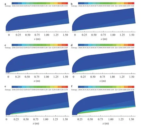
Fig. 4. Entropy contours (J/K), s =cvln p/p∞+cpln ρ∞/ρ, for a 0.15 mm nose, b 3.556 mm nose, c 5 mm nose, d 9.525 mm nose, e 12.7 mm nose and f 25.4 mm nose.
At this point, a final question remains: how much modification to the impedance well is required to "detune"/destroy the second-mode resonance? To address this question, we return to the classic inflection point criterion that ( ρU′)′must change sign[51]. Note from hereon, " ' " denotes wall normal derivative(d /dy). We can determine an estimate for the strength of the acoustic impedance gradient required for second-mode growth by expanding ( ρU′)′=ρU′′+ρ′U′. The condition that ( ρU′)′must change signs leads to ρ′U′=-ρU′′, at the generalized inflection point zero crossing. It should be noted that Lees and Lin's criterion is a necessary, but not a sufficient, condition for boundary layers with a local Mach number greater than one [52]. It is clear from Fig. 6 (left column) that the generalized inflection point criterion is satisfied in all cases and that to satisfy the criterion, the ρU′′term must be balanced by a combination of density or velocity gradients. For the criterion to be dominated by velocity gradients, we definedUˆ′=-ρU′′/ρ′. For the criterion to be dominated by density gradients, we define ρ ˆ′=-ρU′′/U′. Note,Uˆ′and ρˆ′only have physical meaning at the generalize inflection point zero crossing, which is the unique location originally specified by Lees and Lin [51].
Figure6 shows profiles of the generalized inflection point,(ρU′)′,and components(ρU′′, ρ′U′),and the basic state density and velocity gradientsalong withrespectively,at five different streamwise locations which span the entropy swallowing length for the 5 mm nose bluntness case. Note that despite the generalized inflection point criterion being satisfied at all locations (and, by definition, that at the generalized inflection point criterion zero crossingthose streamwise locations upstream of approximately 0.5 m do not exhibit second-mode instability, while those locations downstream do. Also note that in Fig. 6, profiles ofandare plotted only to make the trend from panel to panel clear, as they have no meaning away from the zero point crossing. It is observed that for those streamwise locations upstream of approximately 0.5 m (i.e. within the entropy layer), the generalized inflection point criterion is satisfied based on the strength of the basic state velocity gradients. This means that within the entropy swallowing length the criterion is indicating that velocity gradients are dominant, orat the zero crossing, where second-mode suppression is observed. Whereas, at those locations downstream of approximately 0.5 m (i.e. downstream of the entropy swallowing length), the generalized inflection point criterion is satisfied based on the strength of the basic state density gradients, orat the zero crossing, where second-mode growth is observed. More specifically, consider in Fig. 6 the right column. For the 0.11 m upstream location (top image), at the zero point crossing of the generalized inflection point we observe thatis much greater thanWith each step further downstream (successive figures down the column), we see thatbecomes smaller, whilegets larger, until they swap places, anddominates at a sufficiently downstream position. This is shown more precisely in Fig. 7, which showsu′- ρ′(evaluated at the generalize inflection point location) as a function of axial location for the 5 mm nose bluntness case. A positive value foru′- ρ′indicates that the velocity gradients dominate, whereas a negative value indicates that the density gradients dominate. This implies that secondmode growth is suppressed by the entropy layer "detuning"/destroying the basic state density gradient. Note, these results are consistent with a similar study [53] which was conducted at Mach 10 in a nitrogen flow. Note also, it could be argued that a comparison between the peak amplitudes ofu′and ρ′would also be a relevant comparison. While this is true, here we prefer to tie our results to the generalized inflection point criteria, which also provides for a location from the wall (zero crossing) at which to conduct comparison. In the present case, there is little difference between the two. However, as these concepts are applied to more complex geometries, it may become clear if one is preferable to the other or if there is an optimal alternative location at which to conduct the comparison.

Fig. 5. Shown starting from top to bottom nose radii of: 0.15 mm, 3.556 mm, 5 mm, 9.525 mm, and 12.7 mm. Left column: N-factors. Right column: acoustic impedance profiles () at various streamwise locations.

Fig.6.Shown are results for 5 mm nose bluntness at various streamwise locations. Left column: generalized inflection point criterion. Right column:density and velocity gradients(note legend:
Ultimately, we find that nose bluntness suppresses secondmode growth via entropy layer modulation of the basic state density gradients, which is consistent with the thermoacoustic resonance interpretation of second-modes. Physically, to support second-mode resonance, the boundary layer density gradient must be sufficiently strong to reflect/trap acoustic energy within the boundary layer. Relative to the sharp nose case, where second-mode instability is present, nose bluntness creates a more robust and curved bow-shock. As the flow passes through the curved bow-shock, property gradients (specifically entropy)are generated which impinge on the boundary layer. This impingement creates the so-called entropy layer, the strength and swallowing length of which depend on the flow conditions and nose bluntness. In the present case, it is found that the entropy layer weakens the basic state density gradients, destroying second-mode resonance and thus shifts the laminar to turbulent transition front downstream.
To estimate the amount of density gradient weakening required to destroy second-mode resonance (or conversely the strength of density gradient required to support second-mode resonance), we propose consideration of the generalized inflection point criterion. This is a well-accepted, necessary stability condition in the fluid dynamics community and, when evaluated at the inflection point zero crossing, allows for an estimate of the strength of the velocity and/or density gradients required to satisfy the condition. We find that the generalize inflection point criterion is satisfied at all streamwise location for the 5 mm nose bluntness case, but instability is present only for those in which the density gradients are dominant over the velocity gradients. This is an interesting result, is consistent with the thermoacoustic interpretation of second-modes and suggests an expansion to the application of the generalized inflection point criterion. However, it would be premature to assume this relationship holds in general, until a more thorough and targeted study of the generalized inflection point criteria is conducted.
The mechanism by which nose bluntness suppresses second-mode instability has been investigated by studying 7 degree half-angle straight cones with nose bluntnesses of 0.15 mm,3.556 mm, 5 mm, 9.525 mm, 12.7 mm and 25.4 mm at tunnel conditions relevant to the AFOSR-Notre Dame Large Mach 6 Quiet Tunnel. As expected, our results are consistent with previous studies which find that within the entropy layer, secondmode instability is suppressed. However, here we have explicitly shown that the physical mechanism by which this suppression is achieved is via entropy layer modulation of the basic state density gradient. This is consistent with the thermoacoustic resonance interpretation of second-mode dynamics, i.e. second-mode waves behave as resonant thermoacoustic waves trapped in a thermoacoustic impedance well formed between the strong basic state density gradient and the vehicle wall. We have shown that the entropy layer weakens the basic state density gradient sufficiently enough to destroy this resonance, and thus stabilize the second-mode waves. It should be noted that the relevant mechanism is modification of the thermoacoustic impedance well. In this particular case, the entropy layer provides this modulation. However, over more complex geometries, such modulation may occur for different reasons.
Furthermore, we provided a metric for determining when a second-mode instability will be present by considering the generalized inflection point criterion:noting that at the zero point crossing:Specifically, second-mode instability is present when at the generalized inflection point zero crossing:and is suppressed when at the generalized inflection point zero crossing:That is, when basic state density gradients dominate the generalized inflection point criterion, second-mode instability is present (i.e. the acoustic impedance well is strong enough to support resonance). When basic state velocity gradients dominate the generalized inflection point criterion, second-mode growth is suppressed.
Acknowledgement
The authors thankfully acknowledge support from the Air Force Office of Scientific Research (AFOSR) (Grant FA9550-20-1-0047).
杂志排行

Theoretical & Applied Mechanics Letters的其它文章
- An improved semi-empirical friction model for gas-liquid two-phase flow in horizontal and near horizontal pipes
- Simulation of shear layers interaction and unsteady evolution under different double backward-facing steps
- Particles-induced turbulence: A critical review of physical concepts,numerical modelings and experimental investigations
- Deformation and failure in nanomaterials via a data driven modelling approach
- Nonlinear energy harvesting from vibratory disc-shaped piezoelectric laminates
- Investigation on Savonius turbine technology as harvesting instrument of non-fossil energy: Technical development and potential implementation