Simulation of shear layers interaction and unsteady evolution under different double backward-facing steps
2020-08-10FangDengGuilaiHanZonglinJiang
Fang Deng, Guilai Han,*, Zonglin Jiang
a State Key Laboratory of High Temperature Gas Dynamics, Institute of Mechanics, Chinese Academy of Sciences, Beijing 100049, China
b School of Engineering Science, Chinese Academy of Sciences, Beijing 100049, China
Keywords:Shear layer Interaction Unsteady evolution Jet Numerical simulation
ABSTRACT High-order accurate schemes are employed to numerically simulate the interaction of a supersonic jet and a co-directional supersonic inflow. A double backward-facing step model is proposed to investigate the interaction between the jet shear layer and the supersonic inflow shear layer. It is found that due to the interaction of the shear layer, a secondary jet is injected into the recirculation zone at the intersection of the two shear layers. The secondary jet produced by the interaction of the two shear layers has a periodicity because of shear layers interaction. The distinction in the shape of double backward-facing steps will induce changes in the period of the secondary jet. The analysis and discussion of the periodicity of the secondary jet are mainly focused in this letter.
©2020 The Authors. Published by Elsevier Ltd on behalf of The Chinese Society of Theoretical and Applied Mechanics. This is an open access article under the CC BY-NC-ND license(http://creativecommons.org/licenses/by-nc-nd/4.0/).
During the launch of a rocket, the supersonic jet ejected at the end of the nozzle interacts with the airflow around the rocket [1-3]. In a dual-mode scramjet engine, a fuel injection strut is used in the combustion chamber to improve the mixing of the fuel jet with the supersonic inflow [4, 5]. In a pneumatic nozzle[6], a jet of fuel ejected from the fuel chamber is mixed with a high speed air flow. Hence interaction of jet and supersonic inflow is a considerable phenomenon in fluid mechanics.
The study of the shear layer is limited to the interaction between the shear layer and the shock/expansion wave, shear layer and boundary layer. Manning and Lele [7] directly numerically simulated the interaction between the two-dimensional compression wave and the supersonic shear layer using the esseritially non-oscillatory (ENO) format and the linear compact format hybrid method. It is found that the shock wave leaks outward in the form of acoustic waves on the subsonic side of the shear layer through the braid region between the shear layer vortex pairs. Cohen and Bennett [8] used a laser tester to measure the velocity field of the backward-facing step perturbed by the pulsation of the incoming flow. The interaction between the shear layer and the boundary layer was determined and the results showed that changes in the disturbance frequency resulted in periodic increases and decreases in the recirculation zone.Suzuki and Lele [9] used the geometric acoustic theory and direct numerical simulation (DNS) to investigate the interaction between a two-dimensional supersonic shear layer and an expansion wave. It was found that the compressible wave occurred at the saddle point between the shear layer vortices where leakage occurred.
Deng et al. [10] (here in after referred to as we) developed a double backward-facing step model to simulate the interaction between the two shear layers. But the mechanism of secondary jet generation did not been clearly confirmed, only preliminary conclusions were given and the authors did not fully discuss them. This letter continues to explore the mechanism of secondary jets.
The physical model of the interaction between jet and co-directional supersonic inflow is summarized in Fig. 1. A double backward-facing step model is used in this work. The co-directional supersonic inflow appears above the wallBC. After the inflow passes through the wallBC, the supersonic inflow shear layer takes shape above the wallDE. The jet originates from the wallEF. The other shear layer which called the jet shear layer is created near the boundary of the jet. The mixing zone is the area between the supersonic flow shear layer and the jet shear layer.The effects of the following aspect ratios are investigated:DE/CD=1:1, 2:1, 3:1, and 4:1. The parameters such as density,pressure, and Mach number of the jet and the supersonic inflow are shown in Table 1.
The fifth-order weighted ENO (WENO) scheme [11] and the sixth-order central difference scheme [12] are used to discretize the convection term and the viscous term respectively. The time marching scheme is used for the third order Runge-Kutta scheme [13] and the parallel computation is performed using MPI for the non-blocking communication. 1605×1203 grids and 168 CPU cores are used to run in Guangzhou (Tianhe II).
The Navier-Stokes (NS) equation is dimensionless and uses the following flow parameters
The vector forms are as follows:

After a Jacobian transformation, the two-dimensional NS equation is:

Fig. 1. Physical model of interaction between the supersonic inflow and jet
The vector forms are as follows:
The Jacobian determinant is:
The discrete scheme of the convective term is:
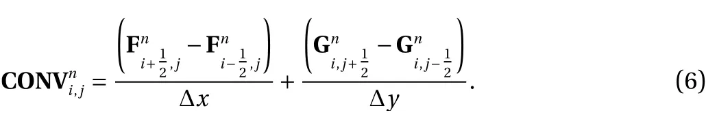
The flux vectors are as follows:

The weighting factor suggested by Jiang and Shu [11] is:

wherenis usually greater than 2 [11]. Coefficients and formulas are as follows
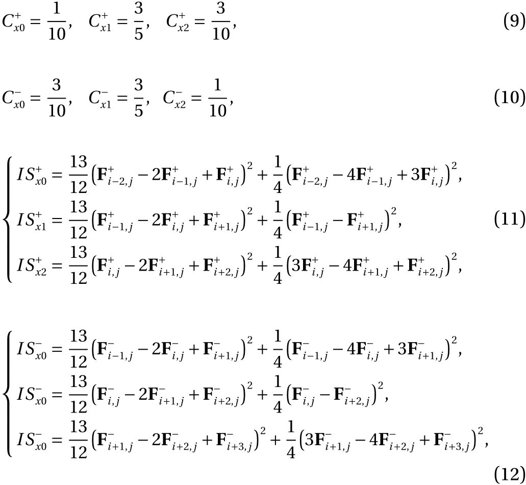
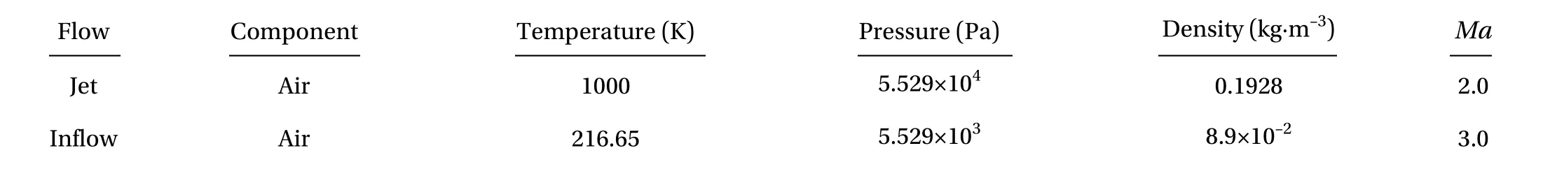
Table 1 Jet/supersonic inflow parameters

The viscous terms semi-discrete [11] are as follows:

The sixth-order central difference scheme [12] is:

The third-order Runge-Kutta scheme [13] is used in this paper. Its form is as follows:
Figure 2 shows the basic structure of the flow field which the pressure ratiopjet/pinflow=10 and the aspect ratioDE/CD=2:1.The length ofCDis used as the dimensionless unit of length. The supersonic inflow withMa= 3 occurs above the first backwardfacing step atBC. After the inflow is separated from pointC, the supersonic inflow shear layer is formed.
A jet withMa=3 occurs on the right side ofEF. Firstly, the jet passes through the triangle-shaped constant velocity core zone,where the temperature, density, etc. are constant. An expansion fan forms nearEFas the outlet static pressure and the ambient pressure do not match. The jet shear layer is formed outside the expansion fan. A mixing zone is the area between the jet shear layer and the supersonic inflow shear layer. The velocity of the air flow in the mixing zone is not so great that the kinetic energy is converted into internal energy. Vortices and oscillating shock waves are formed in this area due to the complex interaction between the jet shear layer and the supersonic inflow shear layer.

Fig. 2. Density gradient map of flow fields with different aspect ratios (pjet/pinflow=10). a DE/CD=1:1, b DE/CD=2:1, c DE/CD=3:1, d DE/CD=4:1

Fig. 3. Evolution of secondary jet injection (pjet/pinflow=10, DE/CD=2:1). a t=0.039 s, b t=0.042 s, c t=0.043 s, d t=0.044 s, e t=0.045 s, f t=0.047 s
The secondary jet [10] impinges on the recirculation zone because of the interaction between two shear layers. After the interaction between the two shear layers, they converge into a mixed layer. Velocities of the mixed layer are not the same on both sides of the shear layer, thereby causing unsteady development of the mixed layer. As shown in Fig. 2a, the mixed layer is broken and unpaired vortex structures are formed. Vortices are formed in the mixed layer, which result in the fragmentation of the mixed shear layer. Two shock waves are formed on both sides of the mixed layer. Because pressures and densities of vortices are lower than those of the surrounding environment, a pressure difference is created. The fluctuation in the pressure causes a disturbance to the mixed layer and shocklets appear on both sides of the mixed shear layer. These shocklets are wrapped in two shock waves as the convective velocity of vortexs change to supersonic velocity relative to the external flow, vortexes produce shocklets [14-16].
As shown in Fig. 2a-d, the flow field structure is similar for the all conditions. However, when theDE/CDof the recirculation zone wall is 1:1, the recirculation zone is small and the injected secondary jet can directly interact with the wall surface.Under the other conditions, the secondary jet is not in contact with the wall directly.
The pressure of the jet is higher than the pressure of the surroundings. This indicates that the jet is an under-expanded jet.We describe the events from 0.039 s to 0.047 s.
The component calibration method is used to observe the secondary jet. Assuming that the density of the jet isρ1and the density of the supersonic inflow isρ2. We defines1=ρ1/(ρ1+ρ2),s2=ρ2/(ρ1+ρ2).Whens1=1 ands2=0, the flow is the jet. Whens1=0 ands2=1, the flow is the supersonic inflow. In other cases, it means the jet and supersonic inflow are blended. This method is used to visualize the injection process of the secondary jets.
Figure 3 shows statuses of different times in a period. This demonstrates the process of production of the secondary jet,which occurs at 0.043 s. The secondary jet can be seen clearly between the jet shear layer and the supersonic inflow shear in the mixed zone. From 0.044 s to 0.047 s, after the secondary jet occurs, the horizontal portion of the jet shear layer declines and the jet shear layer is depressed.
The second shock oscillates in the mixing zone [10]. As we all know, pressures before and after a shock wave are definitely different. So the injection process of the secondary jet can be easily quantified by detecting pressure changes at certain points in the mixing zone. The effects of the following aspect ratios are investigated:DE/CD=1:1, 2:1, 3:1, and 4:1,pjet/pinflow=10. Five pressure points are selected nearCDand their changes are observed.
The pressure ratio of 10 (DE/CD=2:1) is used as an example.As shown in Fig. 4, the pressure changes at the five points are almost the same frequency and they all exhibit 4 periods from 0.01 s to 0.1 s. This is in agreement with the results of the component calibration, where four periods were also detected during the same time. This proves that we can use pressure points to detect the secondary jet mathematically and accurately.
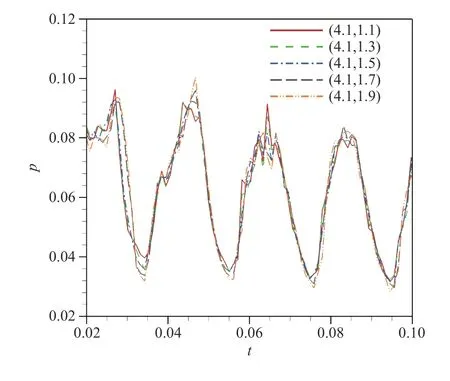
Fig. 4. Distribution of the five pressure points over time(DE/CD=2:1, pjet/pinflow =10)
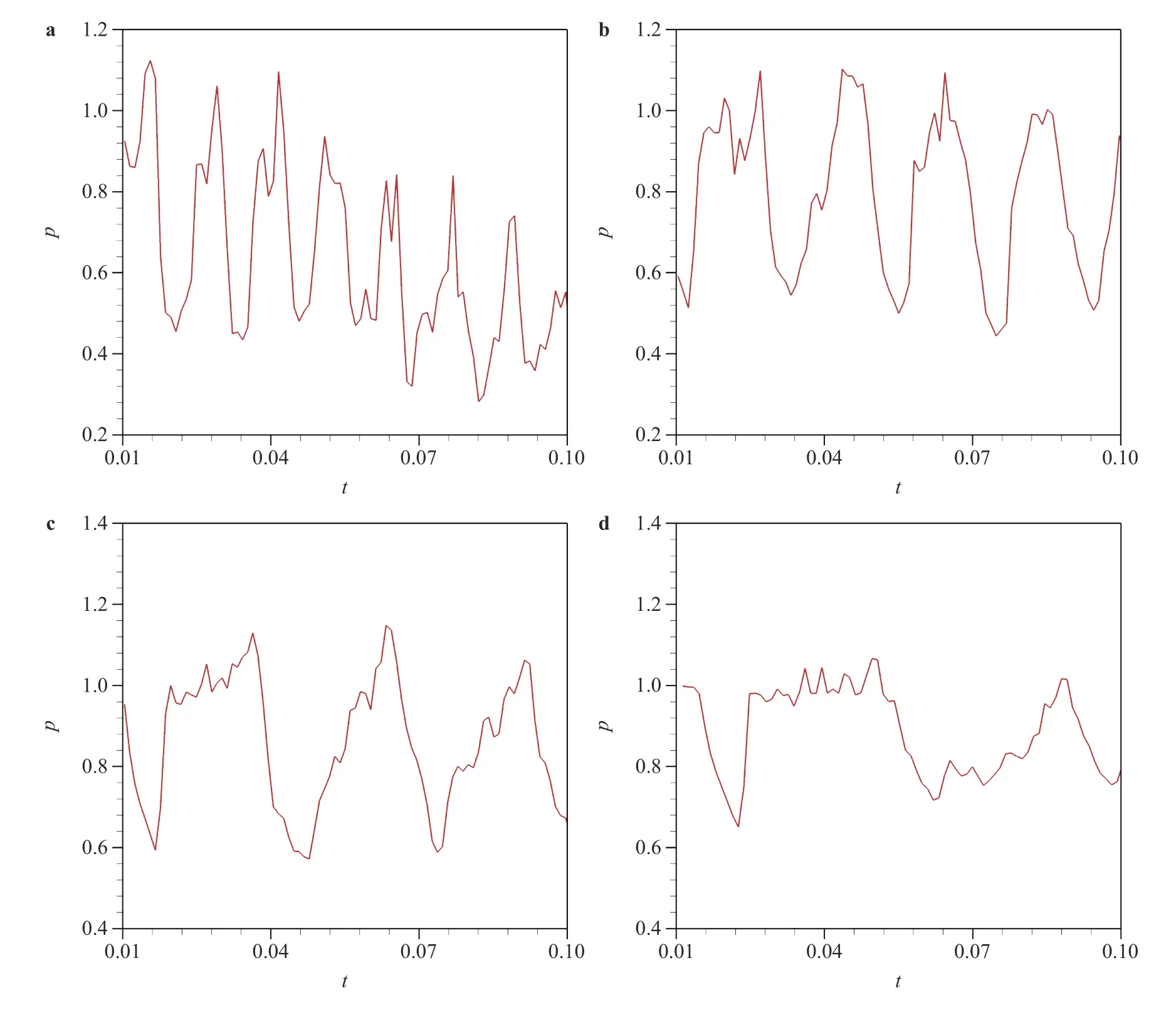
Fig. 5. Wall pressure distribution for different aspect ratios DE/CD (pinflow/pjet =10)
As Fig. 5a shows, whenDE/CD=1:1, the period is very short and ranges from 0.01 s to 0.015 s. As theDE/CDratio increases,the period increases. WhenDE/CD=2:1, the period is approximately 0.025 s, atDE/CD=3:1, the period is about 0.03 s, and whenDE/CD=4:1, the period is about 0.04 s. This indicates that the frequency of the overall periodic fluctuations decreases with increases in the pressure ratios.
At last, we would like to point out some implications of our study. (1) The interaction between inflow shear layer and jet shear layer leads to the formation of thesecondary jet. Two shock waves appear on both sides of the mixed shear layer. Shocklets can be observed in the mixed shear layer. (2) The secondary jet flow has unique periodicity. The periodicity is related to the overall oscillation of the shear layer. The pressure of the mixed zone is influenced by three factors, i.e., the comprehensive perturbation of the jet shear layer, the partial perturbation of the jet shear layer, and the instability of the supersonic shear layer. The comprehensive perturbation of the jet shear layer is the main factor affecting the pressure changes in the mixed zone. (3)When the aspect ratioDE/CDis small, the interaction of the shear layer is intense, and the period of the secondary jet is relatively short, especially whenDE/CD=1:1, the period is only about 0.01 s. However, when the aspect ratioDE/CDis increased, for example, whenDE/CD=4:1, the period increases to 0.04 s. When the aspect ratio increases, the interaction of the shear layer decreases, so the injection period of the secondary jet also becomes significantly longer.
Acknowledgments
This study was supported by the National Key Research and Development Program of China (Grant 2016YFA0401201) and the National Natural Science Foundation of China (Grants 11872066, 11472281, 11727901, and 11532014).
杂志排行

Theoretical & Applied Mechanics Letters的其它文章
- An improved semi-empirical friction model for gas-liquid two-phase flow in horizontal and near horizontal pipes
- On the mechanism by which nose bluntness suppresses second-mode instability
- Particles-induced turbulence: A critical review of physical concepts,numerical modelings and experimental investigations
- Deformation and failure in nanomaterials via a data driven modelling approach
- Nonlinear energy harvesting from vibratory disc-shaped piezoelectric laminates
- Investigation on Savonius turbine technology as harvesting instrument of non-fossil energy: Technical development and potential implementation