Application of multi-dimensional wavelet transform to fluid mechanics
2020-06-06AkiraRinoshikaHirokaRinoshika
Akira Rinoshika*, Hiroka Rinoshika
a School of Aeronautic Science and Engineering, Beihang University, Beijing, 100191, China
b Department of Mechanical Systems Engineering Graduate School of Science and Engineering, Yamagata University 4-3-16 Jonan,Yonezawa-shi, Yamagata 992-8510, Japan
Keywords:Continuous wavelet transform Fluid mechanics Multi-scale flow structures Orthogonal wavelet transform Turbulence Wavelet multiresolution analysis
ABSTRACT This paper first reviews the application research works of wavelet transform on the fluid mechanics. Then the theories of continuous wavelet transform and multi-dimensional orthogonal(discrete) wavelet transform, including wavelet multiresolution analysis, are introduced. At last the applications of wavelet transform on 2D and 3D turbulent wakes and turbulent boundary layer flows are described based on the hot-wire, 2D particle image velocimetry (PIV) and 3D tomographic PIV.
1 Introduction
As a tool for analysis of multiscale signals, the concept of wavelet transform was first formalized in early 1980s by Morlet and Grossmann for the analysis of seismic data [1, 2], and the mathematical foundations of the wavelets were outlined in 1984[3]. However, the application of the wavelet transform on analyzing turbulence data started in 1989 [4]. In the past three decades,there has been a growing interest in applying the wavelet technique to the analysis of various scale turbulent flows. Several review reports on wavelet transform applications in the area of fluid mechanics have been introduced by Farge [5, 6] and Schneider and Vasilyev [7].
Wavelet transform allows time- (or spatial-) and frequencydomain analyses to be combined and decomposes the flow structures based on frequencies or scales. The wavelet analysis may be roughly classified into continuous and discrete wavelet transforms. The former is performed in a smooth continuous fashion, i.e. using the continuous wavelet function, while the latter is carried out in discrete steps, i.e. using the discrete orthogonal wavelet basis function.
The continuous wavelet transform is a power tool to provide continuous time-frequency identification of eddy structures.One-dimensional (1D) continuous wavelet transform has been widely used to analyze the experimental data, such as the wind tunnel turbulence [4], a boundary layer [8, 9], a turbulent jet [10,11], a turbulent wake [12], turbulent shear flows [13, 14], the boundary-layer transition [15, 16], multi-phase flows [17, 18],and laser doppler velocimetry (LDV) and particle image velocimetry (PIV) measurements [19, 20]. Recently, the continuous wavelet transform was also applied to identify the unsteady phenomenon of a simplified tip-leakage flow based on large eddy simulation (LES) simulation [21]. On the other hand, the pressure signals of the gas-solid two-phase flows were also analyzed by using the continuous wavelet transform to identify the particle flow patterns [17].
In contrast, the discrete wavelet transform is characterized by an orthogonal projection on a minimal number of independent modes, allowing quantitative information to be extracted.This transform is further readily invertible, enabling the original data to be reconstructed uniquely for any chosen wavelet basis function from the wavelet coefficients of its inverse transform.Since Yamada and Ohkitani [22] and Meneveau [23] have first decomposed the 1D experimental data of turbulent flows into different scales for statistical analysis, the orthogonal wavelet transform, as an important multi-scale tool, was widely used on analyzing various turbulent flow structures [24, 25]. Mallat [26]developed an orthogonal wavelet multi-resolution technique based on the discrete wavelet transform. This technique may provide a simple hierarchical framework to represent a signal,which allows an event in the signal to be decomposed into several events with fine details. It has potentially capable of decomposing and characterizing quantitatively, other than coherent and incoherent structures, the turbulent structures based on their characteristic frequencies (or scales) in the time (or spatial)domain.
1D orthogonal wavelet multiresolution technique was first developed to decompose flow structures into several wavelet components based on their characteristic or central frequencies,which are representative of the turbulent structures of different scales including large-scale structures, secondary spanwise structures and so on in the near wake of a circular cylinder by Rinoshika and Zhou [27]. It is observed for the first time that the spanwise vorticity contours of the wavelet component at the averaging frequency of Kármán vortices display a secondary spanwise structure near the saddle point in the near wake of a circular cylinder. Based on the same technique, they further studied the effect of various wake-generating bodies or Reynolds number on the different scale turbulent structures in the near and far wakes [28-31]. Their results indicate that the intermediate, as well as the large-scale structures, depend on the wake-generating bodies or Reynolds number. Furthermore, this wavelet technique was also applied to decompose the three-component vorticity data of cylinder wakes into several wavelet components according to their central frequencies [32-34].
As for two-dimensional (2D) wavelet transform, Li et al. [35]first apply 2D wavelet multiresolution technique on analyzing the jet flow images, and visualize the multi-scale turbulent structure of a lobed mixing jet. Then the multi-scale analysis of three velocity component fields in a lobed mixing jet were performed based on analysis of the stereoscopic PIV measurements [36].Zheng et al. [37] combined wavelet transform and the proper orthogonal decomposition (POD) to analyze wake flow. Recently He et al. [38] also extracted the coherent structures of different scales in the turbulent boundary layer by the multiresolution wavelet analysis technique in combination with POD, and revealed a cascade of scales of coherent structures, especially the small-scale ones that are usually difficult to be identified in POD modes of the undecomposed flow field.
As an application on PIV algorithm, the wavelet multiresolution based cross correlation method was derived as part of the development of a PIV [39]. Wavelet image and data compression techniques were also applied to PIV as pre- and post-processing methods [40, 41].
In industry applications, the orthogonal wavelet multi-resolution technique is applied to analyse the multi-scale flow structures around externally mounted vehicle mirror based on the LES simulation [42] and PIV measurement data [43, 44]. They revealed that the separation region is induced by the large-scale vortical structure shed from the root and side portions of the mirror, and the tip and edge of the mirror generate the intermediate and relatively small-scale structures, respectively. Wavelet multi-resolution analysis on three-dimensional (3D) flow structures around the 3D asymmetric bluff body was also investigated by using PIV measurement data [45-47]. Recently this wavelet technique was employed to reveal the various scale flow structures in the barchan dune wakes [48, 49].
With the application of tomographic PIV technique on 3D flow measurements, the development of 3D multiresolution analysis tools becomes more and more important. Recently Rinoshika et al. [50] first proposed the application of 3D wavelet multi-resolution analysis on extracting 3D multi-scale flow structures around a wall-mounted short cylinder based on a high-resolution tomographic PIV data.
On the other hand, the orthogonal wavelet multi-resolution technique was used to analyze the wall pressure-time signals for identifying the particle flow patterns [51-53] in the gas-solid two-phase pipe flow. Recently, orthogonal wavelet multi-resolution technique was first employed to decompose the fluctuating particle velocities of the high-speed PIV for extracting quantitative information on the multi-scale dynamics of particle fluctuation velocity in an air-solid two-phase pipe flow [54-57].Ommena et al. [58] also reviewed application of time-series analysis of gas-solid fluidized beds from in-bed pressure measurements.
With the development of numerical simulation techniques,the investigation of 3D multi-scale flow structures has become more and more necessary. Farge et al. [24, 59] developed a coherent vortex simulation method decomposing the turbulent structures into coherent and incoherent structures based on orthogonal wavelets. Rinoshika et al. [42] and Zheng et al. [49] employed 3D wavelet multi-resolution analysis to extract the multiscale turbulent structures of a vehicle external mirror wake and a dune wake flows based on LES data. Recently Stefano1 [60] also applied wavelet multi-resolution analysis to identify and track energy-containing motions of bluff-body flows for constructing a high-fidelity physics-based adaptive LES method. Moreover,wavelet-based methods have been successfully developed to reduce the computational complexity of numerical simulations,while capturing the essential physics of turbulent flows [7]. Plata and Cant [61] used the wavelet-based multi-resolution analysis to develop a modelling approach to large-eddy simulation and its associated subgrid closure problem.
This paper firstly introduces the basic concepts of one-dimensional continuous wavelet transform, multi-dimensional orthogonal wavelet transform and wavelet multi-resolution technique. Then some applications of wavelet transform on analyzing the complex flow structures of various scale based on the experimental data are described.
2 Continuous Wavelet Transform
2.1 Definition of Continuous Wavelet Transform
Wavelet transform is classified into continuous and discrete(orthogonal) wavelet transforms for capturing local features of data in the time-frequency plane. A continuous time-frequency identification of a signal may be realized by the continuous wavelet transform.
The continuous wavelet transform of a real square integrable function f(t)∈L2(R) (where L2(R) denotes the Hilbert space of measure) at a location b, relative to a real integrable analyzing wavelet ψ(t) at scale a, can be defined as

where Wf(b, a) is called the wavelet coefficient, * stands for complex conjugate and we have

It can be seen that ψb,aplays the same role as eiωtin the definition of the Fourier transform. The continuous wavelet transform is commonly viewed as a numerical microscope whose optics, magnification, and position are given by ψ(t), a, and b, respectively.
In Fourier space the wavelet transform can be expressed as

From the above relationships it can be easily seen that σψb,aincreases with increasing the scale a, and vice-versa. It indicates that wavelet transform can detect high frequency components of signals with sharper time resolution and low frequency components of signals with sharper frequency resolution. This advantage overcomes the limitations of using a fixing scale of window in the short-time Fourier transform.
An arbitrary function satisfying the admissibility condition of wavelet may be used as an analyzing wavelet. Several welldefined wavelet functions, such as Haar, Paul, French hat, m-th derivatives of the Gaussian, Mexican hat, Morlet and Gabor wavelet, are commonly used as the analyzing wavelet. The choice of the appropriate wavelet function is at the user’s disposal and depends on the kind of information what we want to extract from the signal. Here we introduce the Morlet wavelet function (a complex valued function) [12], which often appeared in fluid mechanics. The Morlet wavelet function is given by


It is obvious that the Morlet wavelet function ψ(t) is localized around t = 0, and(ω) is localized around the central of passing band ωc=ω0. In practical applications of signal processing it has been found that a particularly useful value for ωcis the one for which the wavelet scale a represents the period. Therefore, the central of passing band is defined as ωc=ω0=2π. Then ψb,a(t) is centered at the position b with the standard deviation, and(ω) is centered at the central of passing band 2π/a with the standard deviation. This wavelet function is complex,enabling one to extract information about amplitude and phase of the process being analyzed. Using the Morlet wavelet function, wavelet coefficients of Eq. (1) can describe a signal as localized strength of a signal over a 2D time-period plane [12].
2.2 Wavelet Correlation methods
In any nonstationary situation, such as in human speech,music, velocity signals of turbulence and others, signals contain various frequency components that rapidly change with time in complex ways. The conventional auto-correlation method is quite capable in identifying the self-similarity structure.However, it cannot extract the information of the self-similarity structure in frequency space and had been hiding the essence of the self-similarity feature since it lacks frequency resolution. The conventional auto-correlation method is well suited to analyze the periodic signals and is not suited for complex signal analysis.Although the wavelet transform can describe when those frequency components occurred, more powerful techniques must be developed to gain deeper insight into the complex self-similarity behavior of signals.
As described in the previous section, the wavelet coefficients can describe a signal as localized strength of the signal in both time and period or frequency spaces. The wavelet coefficients have been employing to describe the characteristics of a signal.Therefore, the all conventional statistics method may be applied.In order to obtain the self-similarity structure of a signal for various scales at any given time delay, at first, we unfold the signal into a 2D time-period plane by the wavelet transform. Then we use its wavelet coefficients to define an auto-correlation function, called the wavelet auto-correlation function WC(a, τ) [11],by the following formula.

where τ is time delay of wavelet coefficients in the wavelet space,or the time delay of the signal f(t). It is evident that the wavelet auto-correlation function can provide important self-similarity features on a 2D period-time delay plane, and then extracts the most essential frequencies governing the self-similarity features of signals. We define a wavelet auto-correlation coefficient WR(a, τ), which is normalized with respect to the wavelet autocorrelation function at τ=0, as follows:

In identifying the spatial turbulent structure or coherent structures and its evolution in time, the cross-correlation analysis between velocity components measured at two separated points in flow field is most used. A difficulty with the conventional cross-correlation method, however, is that the cross-correlation function only provides information about the cross-correlation behavior in terms of time delay but no information about correlation behaviors in scale space at each scale due to lack of scale resolution.
In analogy with the wavelet auto-correlation, we first unfold,respectively, two different signals fx(t) and fy(t) into their two- dimensional time-period planes using the wavelet transform, in order to yield the period resolution. Then their wavelet coefficients, Wfx(b, a) and Wfy(b, a), are used to define a cross-correlation function, called the wavelet cross-correlation function WCxy(a, τ) [12], by the following formula.

where τ is a time delay between two signals. The wavelet crosscorrelation function has the following two characteristics. (1)Since the wavelet cross-correlation function is obtained by integration of wavelet coefficients over time plane, contributions of different period to the correlation are kept reasonably separated. (2) This separation is achieved without excessive loss of resolution in time variable due to use of the wavelet transform(of course, subject to the limitation of the uncertainty principle).The two characteristics exhibit the property known as timeperiod localization. Therefore, the wavelet cross-correlation function can describe important statistical correlation features between two different signals on a 2D scale-time delay plane,and extract the most essential scales governing the correlation features, which is lost if using traditional method.
In order to characterize the cross-correlation, it is convenient to introduce a wavelet cross-correlation coefficient W Rxy(a,τ) [12]

3 Multi-dimensional Orthogonal Wavelet Transform
The orthogonal discrete wavelet transform shows the local features of data in the time and frequency bands. However, the wavelet coefficients of each frequency band are orthogonal independently of each other. The orthogonal wavelet transform provides enough temporal resolution in the high frequency ranges and low time resolution in the low frequency range.Therefore, the limitations of conventional bandpass transform are overcome, in which a filtering technique with fixed time-frequency resolution provides good frequency resolution for frequency events and includes redundant information. Furthermore, the orthogonal wavelet transform is further reversible so that the measured signals or images can be uniquely reconstructed based on a wavelet basis function selected from the inversely transformed wavelet coefficients.
3.1 1D Orthogonal Wavelet Transform
In this section we briefly describe the 1D orthogonal discrete wavelet transform based on Daubechies wavelet basis.

where the superscript T denotes a transposed matrix and the matrix CNis Daubechies wavelet basis with an order of 12.
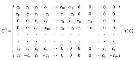
As evident in the structure of the matrix CN, two convolution operations are carried out. The odd rows of matrix perform an ordinary convolution with coefficients c0, c1, c2, …, c10and c11acting as a low-pass (smoothing) filter, while the even rows perform a different convolution with coefficients c11, -c10, c9, …, c1and -c0acting as a high-pass (difference) filter. The resulting first transform coefficient matrix, Vwconsists of interlaced smooth and difference coefficients, denoted byand(i=1, 2, …,2N-1). Since the square matrix CNis a non-singular matrix, its rank is N. By multiplying with a permuting matrix PNas

The odd rows of matrix Vware moved forward as the first 2N-1elements and the even rows of matrix are moved backward as the last 2N-1elements. The last 2N-1difference elements of, i.e.thecoefficients, are called the wavelet coefficients at level N-2.
The wavelet basis matrix CN-1and the permuting matrix PN-1,which are the halves of CNand PN, respectively, are then applied to the first 2N-1smooth elements of. The 2N-2smoothcoefficients and 2N-2differencecoefficients are generated in this operation, the latter coefficients corresponding to the wavelet coefficients of the hierarchical level N-3. This pyramidal procedure is repeated until the last hierarchical level 1 consisting of eightcoefficients is obtained. The orthogonal discrete wavelet transform can be expressed in matrix form by

where S and W are respectively discrete wavelet coefficient matrix and analyzing wavelet matrix of VN. W is usually constructed based on a cascade algorithm of an orthogonal wavelet basis function.

In general, wavelet basis functions are chosen such that W satisfies WTW = I, where I is a unit matrix. This condition enables the discrete wavelet transform to be an orthogonal linear operator and invertible. The inverse orthogonal discrete wavelet transform can be simply performed by reversing the procedure,starting with the lowest level of the hierarchy, that is,

The orthogonal wavelet transform produces coefficients that contain information on the relative local contribution of various frequency bandwidths to the transformed data instead of the frequency components of the original data. In order to obtain the grouped frequency components of the transformed data, the orthogonal wavelet coefficient S is first decomposed into the sum of all levels:
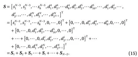
The inverse orthogonal wavelet transform is then applied to the coefficient of each level, viz.

where terms WTS1and WTSN-2represent the data components at wavelet level 1 (the lowest grouped frequency) and level N-2 (the highest grouped frequency). It is evident that the sum of all wavelet components can be used to reconstruct the original data in the case of the orthogonal wavelet bases. This decomposition method is referred to as 1D wavelet multi-resolution technique.
For considering the effect of orthogonal wavelet basis, some orthogonal wavelet functions (Daubechies, Harmonic, LMB and Meyer) were used by Mouri et al. [25]. They suggested that the statistics of turbulent flow were insensitive to the choice of the wavelets.
Figure 1 shows a comparison of wavelet components of particle velocity fluctuation in a gas-solid two-phase flow [54]when using different order of Daubechies wavelet bases. It is evident that the results of the wavelet multi-resolution analysis are essentially independent of the choice of wavelet basis having an order higher than 10.
3.2 2D Orthogonal Wavelet Transform
Just as the 1D discrete Fourier transform is extended to two dimensions, for a 2D array FNof size 2N×2N, its 2D wavelet transform is most easily obtained by transforming the array sequentially on its first index (for all values of its other indices),then on its second, i.e. making repeated use of the 1D wavelet transform in the horizontal and vertical directions. In this secc11) (Eq.(10)) is used. The first orthogonal transformation, which tion, the Daubechies orthogonal wavelet basis of 2N×2Nmatrix CNwith an order of 12 having twelve coefficients (c0, c1, c2, …,decomposes the original array FNinto four distinct submatrices:the vertical detailed (difference) coefficients of 2N-1×2N-1matrix, the horizontal detailed (difference) coefficients of 2N-1×2N-1matrix, the diagonal detailed (difference) coefficients of 2N-1×2N-1matrixand the remaining approximation (smooth)coefficients of 2N-1×2N-1matrix S1, is performed by the multiplication of an orthogonal matrix.
When T. J. showed up at school on Monday morning, he arrived to a firestorm. A group of teachers were protesting to the school principal about his being elected co-chairman. The very first communitywide service project was to be a giant food drive, organized by the Homeless Project team. These teachers couldn t believe that the principal would allow this crucial beginning to a prestigious13, three-year action plan to stay in the incapable14 hands of T. J. Ware.

where the superscript T denotes a transposed matrix. As described in 1D wavelet transformation, the matrix PNis employed to permute the matrix such that the odd rows of matrix are moved forward as the first 2N-1elements and the even rows of matrix are moved backward as the last 2N-1elements.The detailed (difference) coefficientsandare called the wavelet coefficients at level N-2.
The second orthogonal transformation is further to decompose only the approximation (smooth) coefficients of 2N-1×2N-1s ubmatrix S1by using the wavelet basis matrix CN-1and the permuting matrix PN-1, which are consist of the halves of CNand PNand unit matrix.
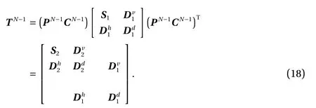
The detailed (difference) coefficients contained within 2N-2×2N-2submatricesandcorresponding to the wavelet coefficients at level N-3 and the approximation (smooth)coefficients within 2N-2×2N-2submatrix S2are generated in this operation. This pyramidal procedure is repeated until the last hierarchical level 1 of 23×23submatrix SN-3is obtained.
Therefore, the orthogonal discrete wavelet transform can be expressed in matrix form by
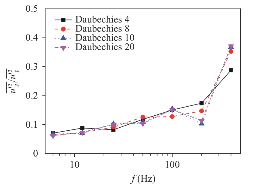
Fig. 1. Comparison of wavelet components among the orders of Daubechies wavelet bases
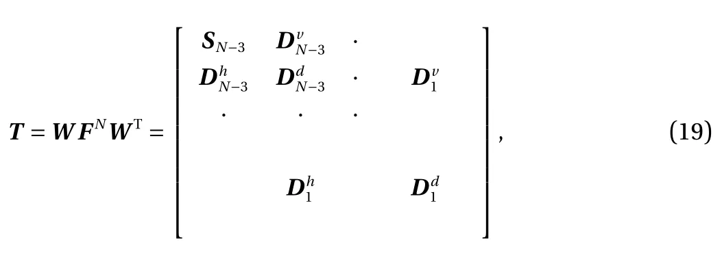
where T and W are discrete wavelet coefficient matrix and analyzing wavelet matrix, respectively. In the pyramidal operation, W is usually constructed based on a cascade algorithm of an orthogonal wavelet basis function, viz.

In general, wavelet basis functions are chosen such that W satisfies WTW = I, where I is a unit matrix. This condition enables the discrete wavelet transform to be an orthogonal linear operator and invertible.
The inverse orthogonal discrete wavelet transform can be simply performed by reversing the procedure, starting with the lowest level of the hierarchy, that is,

The orthogonal wavelet transform produces coefficients that contain information on the relative local contribution of various wavelet levels to the transformed data instead of the wavelet level components of the original data. In order to obtain the wavelet level components of the transformed data, similarity to 1D wavelet multi-resolution analysis, the orthogonal wavelet coefficient matrix T is first decomposed into the sum of all levels:
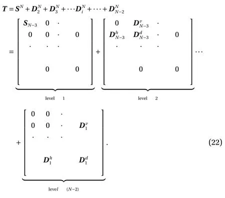
The inverse orthogonal wavelet transform is then applied to the coefficient of each level, viz.

3.3 3D Orthogonal Transform
This section introduces the 3D orthogonal wavelet transform and its application. Here we use the orthogonal Daubechies wavelet basis with an order of 12 (2N×2Nmatrix CN) having twelve coefficients (c0, c1, c2,…, c11) (Eq. (10)).
The following contents describe the operations. As the wavelet transform of the first level, the data array of the horizontal direction (x-direction)(j=1, 2, …,2N; k=1, 2, …, 2N) is carried out by multiplying two matrices at first step.

Here the superscript T represents a transposed matrix. The resulting first transform coefficient matrix,, is composed of interlaced smooth and difference coefficients, denoted byand. By the multiplication of a permuting matrix PN, we obtain the first wavelet coefficients VNalong the x-direction as

At this step, the even rows of the matrix are moved backward as the last 2N-1elements and the odd rows of the matrix are moved forward as the first 2N-1elements.
The second step is to divide 3D matrix(i=1, 2, …, 2N; j=1,2, …, 2N; k=1, 2, …, 2N) (Eq. (25)) into two block matrices as:

By multiplying with a permuting matrix CNand PNalong the y-direction, the above two block matrices are transferred as
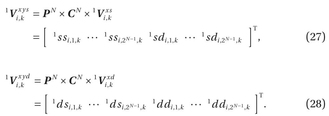
Therefore, we obtain the following 3D matrixby transformation along x- and y-direction.
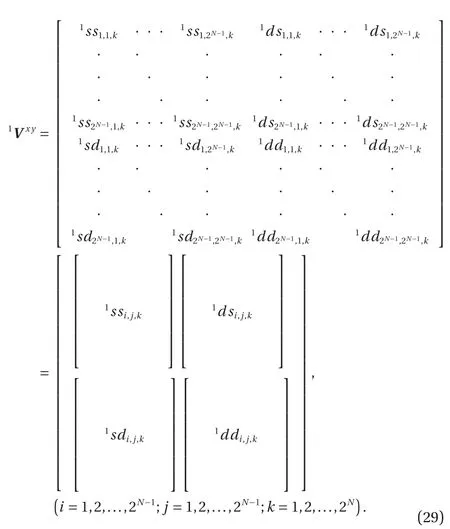
The following four block matrices consist of:

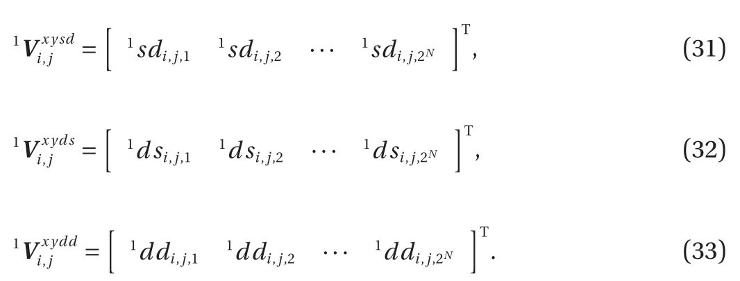
At the third step, along the z-direction the four block matrices are decomposed by the wavelet basis matrix CNand the permuting matrix PNinto
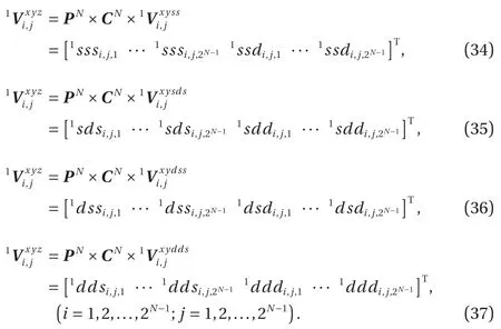
Finally, as indicated in Fig. 2, the following eight block matrices consist of the first wavelet transform coefficients of matrixandHereandare the wavelet coefficients of level 1
The wavelet transform of the second level is performed to the smooth block matrices ofk=1,…,2N-1) based on the wavelet basis matrix CN-1and the permuting matrix PN-1, which are the halves of CNand PN, respectively. Along x-, y- and z-direction in a similar way to the first level transform, the wavelet transform coefficients of level 2andare obtained. The illustration of the 3D orthogonal wavelet transform is displayed in Fig. 2. The pyramidal computation is operated until the matrix of the last wavelet level only consists of 23×23×23elements. At last the 3D wavelet coefficients S is written as

Here W satisfies WTW = I, here I is a unit matrix. It indicates that the 3D discrete wavelet transform is an orthogonal linear operator and invertible. We may perform the inverse orthogonal wavelet transform by reversing the procedure as follows.

Being similar to 1D and 2D wavelet multi-resolution techniques, the orthogonal wavelet coefficient of matrix S is first resolve into the following sum of all levels:

Then we apply the inverse orthogonal wavelet transform to the wavelet coefficients, viz.

4 Applications of Wavelet Transform on Analysis of Flow Structures
4.1 Applications of Continuous Wavelet Transform
Considering a 2D turbulent wake generated by a circular cylinder of d =12.5 mm, a cross-hot wire was used to measure the fluctuating velocities on the position of vortex path at x/d =20 (x is the streamwise distance downstream). Here the free-stream velocity is U =6.7 m·s-1, corresponding to Reynolds number of Re= 5600. At first the vertical component of fluctuating velocity v, as shown at the bottom of Fig. 3, is analyzed by the Fourier analysis,and its spectrum is plotted on the left of Fig. 3. It is observed that an evident peak appears at frequency of 109 Hz, which is indicating Kármán vortices. Then fluctuating velocity v is analyzed by the continuous wavelet transform (Eq. (1)) with the help of the Morlet wavelet (Eq. (3)). The real part of continuous wavelet coefficients Wv(t, f) (abscissa: time t, ordinate: frequency: f, color contour for magnitudes of wavelet coefficients) is shown in Fig. 3. It is clearly observed that alternative strong positive and negative peaks of Wv(t, f) appears at f = 109 Hz, which implies the passing of Kármán vortices. It is also found that the larger positive and negative peaks of fluctuating velocity v correspond to the peaks of Wv(t, f) at lower frequency, and smaller peaks of fluctuating velocity v correspond to the peaks of Wv(t, f) at higher frequency. Furthermore, alternative strong positive and negative peaks of Wv(t, f) around f = 200 Hz (t=12-46 ms) and f = 300 Hz (t=35-50 ms) can be observed. They imply the periodic multiscale vortical motions exist in the Kármán vortices. From a positive peak of f = 109 Hz around t = 46 ms, an evident branching structure, which consists of two peaks of f = 200 and four peaks of 300 Hz, may be clearly observed. This indicates that a largerscale motion containing several smaller-scale motions passes through this location.
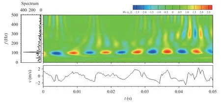
Fig. 3. Continuous wavelet transform of fluctuating velocity on the position of vortex path
In order to investigate self-similarity structures of the wake at various frequencies, the wavelet auto-correlation of the fluctuating velocity (Fig. 3) are computed based on Eqs. (5) and (6). The wavelet auto-correlation coefficient WR(τ, f) is shown on the (τ,f) color plane (abscissa: time delay τ, ordinate: frequency f, rainbow colors for wavelet auto-correlation coefficient) in Fig. 4. Below the color plate, the traditional autocorrelation coefficients R(τ) is also illustrated. From the distribution of WR(τ, f) in Fig. 4,the dominant periodic positive and negative peaks at f = 109 Hz are evident, and indicate that the strong periodic Kármán vortex through this position. Making a comparison between WR(τ, f)and R(τ), it is found that the alternative strong positive and negative peaks of WR(τ, f) at f = 109 Hz correspond to the large positive and negative peaks in R(τ). Furthermore, several alternative positive and negative peaks of WR(τ, f) around f =200 Hz, 300 Hz,400 Hz, and 500 Hz decrease with increasing τ, implying periodic multi-scale flow structures. This also indicates that a periodic larger-scale motion contains periodic smaller-scale motions.Therefore, it may say that the distribution of WR(τ, f) exhibits a map of multi-scale similarity structure.
4.2 Applications of 1D Orthogonal Wavelet Transform
Two orthogonal arrays, each of eight cross-wires, were used to measure a 2D circular cylinder (d =12.5 mm) wake at the downstream of x/d =20. The Reynolds number Re was 5600.Eight cross-wires were aligned in the (x, y)-plane, i.e. the plane of mean shear, and eight in the (x, z)-plane, which is parallel to both the cylinder axis and the streamwise direction. The sixteen cross-wires allow velocity fluctuations u and v in the (x, y)-plane and u and w in the (x, z)-plane to be obtained simultaneously.The detailed information on experimental setup can be found in Rinoshika and Zhou [27].
It is necessary to determine the fundamental central frequency of turbulent structures before the wavelet multi-resolution analysis. This frequency is presently specified at the averaging frequency f0=109 Hz of Kármán vortices based on the Fourier analysis.
Once the fundamental central frequency is determined, the v-signal on the position of vortex path is decomposed using the wavelet multi-resolution technique, which yields thirteen wavelet levels or components (the number of wavelet levels is determined by the number of sample data items and the order of wavelet basis). Here the Daubechies wavelet base with an order of 20 was used. The spectrum obtained from the Fourier analysis of each wavelet component displays a peak, representing the corresponding central frequency, and spreads over a range of frequencies. The spectrum of wavelet level 9, whose central frequency, identified with the most pronounced peak, corresponds to f0. Subsequently, the central frequencies of wavelet levels 8,10, 11 and 12 are given by f0/2, 2f0, 4f0and 8f0, respectively.
In order to better ‘visualize data’, sectional streamlines, referred to as streamlines for simplicity in the following, were constructed for each wavelet component as well as for measured velocities. The streamlines are viewed in a reference frame translating at the convection velocity of the large-scale structures,which is Uc= 0.87U.
Figure 5 shows instantaneous streamlines and corresponding normalized vorticity contours, ωzd/U in the (x, y)-plane and ωyd/U in the (x, z)-plane, respectively. Both streamlines and vorticity contours in the (x, y)-plane display the quasi-periodical large-scale organized structures of negative vorticity. Organized structures are discernible in the (x, z)-plane. However, it would be difficult to study the behaviors of the structures other than the large-scale ones in either plane.
By using 1D wavelet multi-resolution technique, each velocity component is decomposed into thirteen wavelet levels or components based on the central frequencies or wavelet levels at each position along the time direction. Then we use wavelet velocity component of each wavelet level to construct the instantaneous streamlines and corresponding normalized vorticity contours similar to Fig. 5.
Figures 6-8 present streamlines and vorticity contours in both planes calculated from the wavelet components of velocity at the central frequencies of f0, 2f0and 4f0. Different components are identified by their central frequencies, given as a subscript.The convection velocity of Uc =0.87U for large-scale coherent structures was used for the reference frame speed to calculate the streamlines for the wavelet components of f0and 2f0and the local mean velocity was used for the other components of higher central frequencies. Figure 6 shows streamlines and vorticty contours for the wavelet component at the central frequency f0.The vortical structures shown in Fig. 6 have a good correspondence to those in Fig. 5. However, the flow structures in Fig. 6 appear better organized and exhibit a much stronger periodicity,indicating the capacity of the present technique to extract largescale coherent structures from turbulent velocity data.
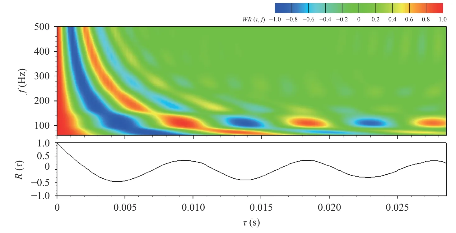
Fig. 4. Wavelet auto-correlation coefficient of fluctuating velocity on the position of vortex path
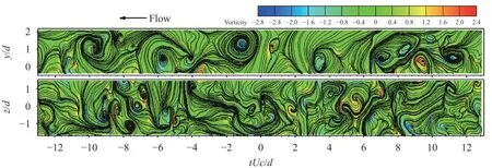
Fig. 5. Measured instantaneous sectional streamlines and vorticity contours
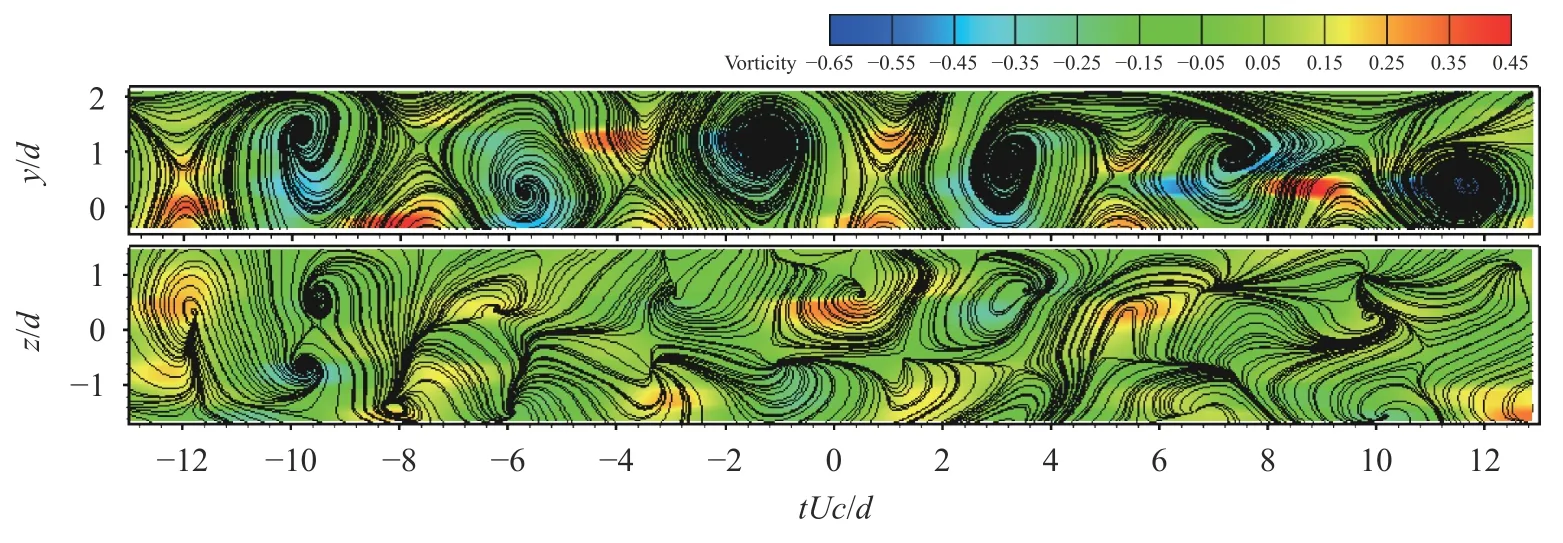
Fig. 6. Instantaneous sectional streamlines and vorticity contours of the wavelet component at f0
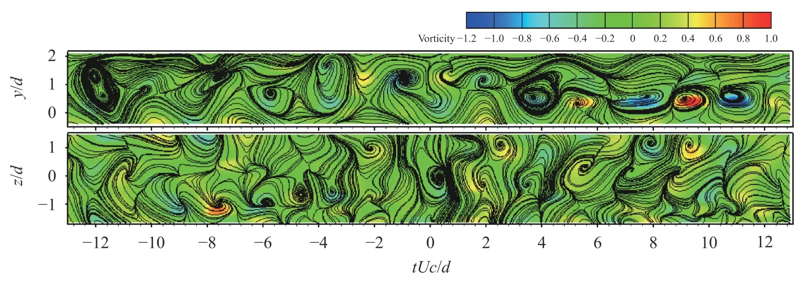
Fig. 7. Instantaneous sectional streamlines and vorticity contours of the wavelet component at 2f0
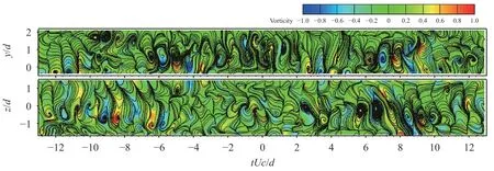
Fig. 8. Instantaneous sectional streamlines and vorticity contours of the wavelet component at 4f0
As the central frequency increases to 2f0, the spanwise vortical structures in the (x, y)-plane (Fig. 7) mostly associate with large-scale spanwise structures and identified from the streamlines of the wavelet component at f0. Streamlines (Fig. 7) in the(x, z)-plane show a different flow structure from that (Fig. 7) in the (x, y)-plane. The vorticity strength in both planes almost doubles that at the central frequency of f0. The difference suggests that the flow structures in the (x, y)-plane are connected to primary or secondary spanwise structures, while those in the (x,z)-plane result from the three-dimensionality of primary spanwise structures and rib structures.
Once the central frequency reaches 4f0, as shown in Fig. 8,the smaller scale structures appear all over the flow. The streamlines show turbulent structures, not so distinct albeit discernible,between the two planes as the wavelet components of f0(Fig. 6)and 2f0(Fig. 7). The vorticity concentrations tend to be arranged alternately in sign along the flow direction in both planes.
The wavelet components of the time-averaged Reynolds stress, represent the contributions from the turbulent motions of various scales to the Reynolds stresses, are calculated from the wavelet components of instantaneous velocity. Figure 9 plots the lateral distributions ofat different central frequencies, as compared with the measured values. Hereis the maximum value of the measured data. The distributions ofare similar to that of the measured data, varying greatly with the central frequency. It is observed that the coherent contribution from the large-scale (f0) and intermediate-scale(2f0) vortical structures to the Reynolds stresses is larger, accounting for almost 74%. This indicates that the wavelet components of f0and 2f0are most energy-containing.of 2f0are very close to that of f0, implying that energies associated with the two central frequencies are quite comparable. For the central frequency greater than 4f0,tends to fall off quickly.
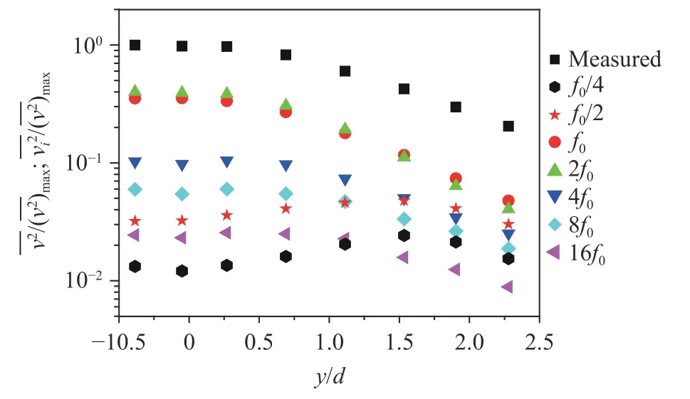
Fig. 9. Velocity variances of the measured and the wavelet components at various central frequencies
By using the same method, other velocity and vorticity variances of the wavelet components can be also calculated [27].
4.3 Applications of 2D Orthogonal Wavelet Transform
A typical application of 2D orthogonal wavelet transform is to decompose 2D velocity or vorticity fields into multi-scale flow structures from PIV measurement data. Here we introduce a 2D wake flow around an asymmetric side mirror of the race car constructed by a compound of 1/4 circular and triangle cylinders in Fig. 10 [46]. The experiment was conducted in the circulating water channel, and the PIV measurement were carried out at a constant free stream velocity of U0= 0.29 m/s, which corresponds to Reynolds number Re (≡U0L/ν) = 14,440.
4.3.1 Instantaneous flow structures of various scales
The instantaneous streamlines and corresponding normalized vorticity contours of ωzL/U0and ωyL/U0in the (x, y)- and (x,z)-plane are shown in Fig. 11. The color mappings have been assigned to the vorticity values and the highest and lowest concentrations are respectively displayed as red and blue.
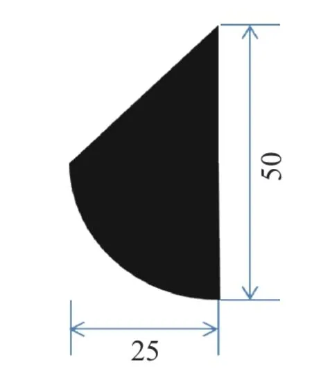
Fig. 10. Model
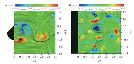
Fig. 11. Instantaneous streamlines and normalized vorticity contours
The instantaneous velocity components (64× 64) obtained by PIV are decomposed into three wavelet levels or wavelet components in by the 2D orthogonal wavelet multi-resolution analysis. The Daubechies wavelet matrix with an order of 12 is used as the analyzing wavelet matrix In order to analyze the spectral characters of each wavelet component, the fast Fourier transform is used to analyze each wavelet component. Corresponding to the scale of wavelet components in 1D orthogonal wavelet multi-resolution analysis, the wavelet level 1 having central scale of 25 mm represents the large-scale structure, and the wavelet level 2 having central scale of 12.5 mm represent the intermediate-scale structure whilst the wavelet level 3 with central scale smaller than 6 mm refers the relatively small-scale structures.
Figure 12 shows the 2D instantaneous streamlines and vorticity contours of the wavelet components at level 1, level 2 and level 3 in the (x, y)-plane. The large-scale streamlines and the positive and negative peaks of vorticity contours at level 1 (central scale of 25 mm) in three wakes are likely representative of large-scale structures, having a good correspondence to those in Fig. 11a. The observation indicates a correspondence between the large-scale wavelet component and the large-scale vortical structures. They are apparently the uppermost and energy-containing structures and make the most contribution to flow structure.
When decreasing the scale of structures to level 2 (central scale of 12.5 mm), as shown in Fig. 12b, many positive and negative peaks that imply intermediate-scale structures appear in the whole measured field. Some of them are apparently associated with the large-scale vortices. Meanwhile, the decrease in the vorticity strength in the intermediate-scale vorticity components, compared with that of the large-scale vorticity components, is particularly evident.
For the small-scale streamlines and vorticity at level 3 (central scale smaller than 6 mm), the relatively small-scale structures are observed in the whole flow field. The high vorticity concentration comes from the shear layer.
The 2D instantaneous streamlines and vorticity contours of the wavelet components from level 1 to level 3 in the (x, z)-plane are shown in Fig. 13. Not only the large-scale structures that coincide with the measured PIV data in Fig. 11b are observed, but the stronger intermediate- and small-scale structures are also extracted. The wake exhibits that the intermediate-scale structures dominate the flow structure, although some higher vorticity concentrations (strong vortices) appear in the large- and small-scale structures.
4.3.2 Contributions to the Reynolds shear stresses from different wavelet components
Figure 14 shows the distribution of the normalized Reynolds shear stress contours ofin the (x, y)-plane. The distributions ofexhibit the maximum values near the end of the separation bubble.
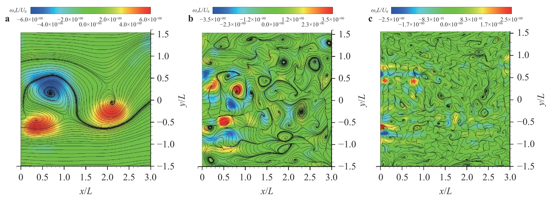
Fig. 12. Streamlines and vorticity contours of various wavelet components in the (x, y)-plane
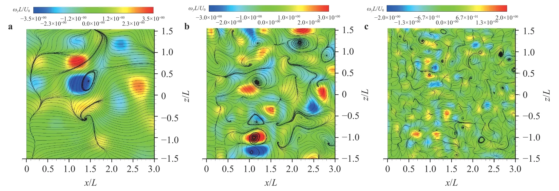
Fig. 13. Streamlines and vorticity contours of various wavelet components in the (x, z)-plane
In order to analyze the multi-scale components of Reynolds shear stresses, the fluctuating velocity components of all measurement region obtained by PIV are first decomposed into eight wavelet levels in the time direction by the 1D wavelet multi-resolution technique. Then the Reynolds shear stresses of the wavelet components are obtained by computing fluctuating velocity of wavelet components at each level. The results are shown in Fig. 15, which represent the contribution from each wavelet level(frequency), i.e. the turbulent structures of a range of scales, to the Reynolds shear stresses. This information is of fundamental importance and valuable for numerical modeling. The region of the maximumat wavelet level 1 (f0= 0.73 Hz) coincides approximately with that in Fig. 14 associated with large-scale structures. It indicates that the most significant contribution to the Reynolds shear stresses comes from the large-scale structures.
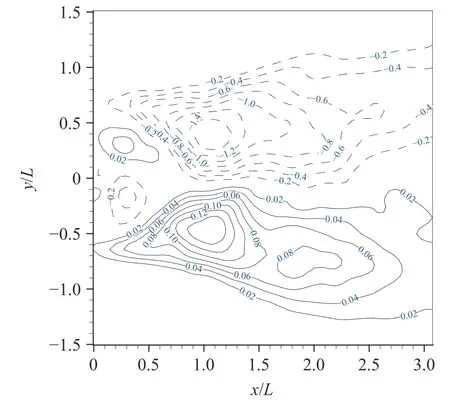
Fig. 14. The measured Reynolds shear stresses in the (x, y)-plane
As increasing the wavelet level to 2 and 3 (f0= 1.2 and 2.2 Hz).The maximumappears in the shear layer and the separation bubble, which indicates the contribution from the shear layer separation. It suggests that the intermediate-scale structures also play a role.value decreases compared with that of the large-scale structures.
When the wavelet level increases from 4 to level 8 (f0= 5 to 86 Hz), thevalue of the wavelet component appears falling off rather rapidly. It implies that less contribution to the Reynolds shear stresses comes from the small-scale structures. The maximumis observed in the separation bubble in the shear layer.
4.4 Applications of 3D Orthogonal Wavelet Transform
Since Farge et al. [59] developed a coherent vortex simulation method decomposing the turbulent structures into coherent and incoherent structures based on 3D orthogonal wavelets,3D orthogonal wavelet transform is often used to extract 3D multi-scale flow structures based on the numerical simulation data [42, 49]. However, few researches on the 3D orthogonal wavelet analysis of 3D experimental data have been found. Here,we introduce an application of 3D wavelet multi-resolution analysis on 3D tomographic PIV data [50].
A short circular cylinder with a height of H =70 mm and a diameter of D = 70 mm (the aspect ratio of H/D = 1) was placed on the central axis of the bottom wall in a circular open water tunnel. A free stream velocity was fixed at U = 0.162 m/s, corresponding to Reynolds number Re of 8570. The experimental apparatus for the tomographic PIV measurements are shown in Fig. 16. Illumination was provided by a dual-head Nd:YAG laser(500 mJ/pulse, 532 nm wavelength) with a pulse separation time of 3 ms. Four high-resolution (6600 × 4400 pixels2, 12bit) doubleexposure CCD cameras (IMPERX SM-CCDB29M2) were applied to record the measurement domain simultaneously.
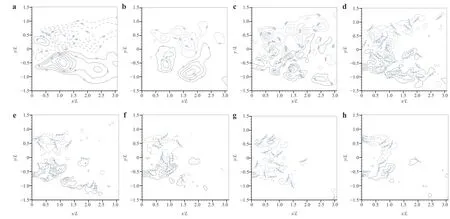
Fig. 15. Reynolds shear stresses of wavelet components in the (x, y)-plane
Figure 17 shows the 3D distribution of the instantaneous Q criterion with isosurface of Q/(U/D)2=13.5 colored by the streamwise vorticity ωxD/U. It is observed that 3D various scale vortical structures and an instantaneous arch vortex, as indicated by 1 in Fig. 17, are clearly observed. It is also clearly observed that the arch vortex rapidly breaks down into several fragments at the downstream. For example, the several vortex structures labeled 2, 3, and 4 may be identified as fragments of the arch vortices in Fig. 17.
In order to reveal the 3D multi-scale flow structures behind the short cylinder, the 3D wavelet multi-resolution technology is first applied to 3D instantaneous velocity field of Tomographic PIV. 3D velocity data are decomposed into three velocity wavelet components based on their characteristic scales or central scales, which are representative of the large-, intermediate- and small-scale structures, by using orthogonal wavelet multi-resolution technique. Here the large- and intermediate-scale structures are respectively represented by wavelet component of levels 1 and 2, and the small-scale structure consists of level 3 and level 4. Based on the resolution of our Tomographic PIV, the large-scale structure has the central scale of a = 38.4 mm, intermediate-scale structure has the central scale of 19.2 mm, and small-scale structure has the central scale of 7.2 mm.
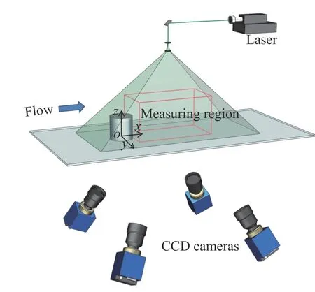
Fig. 16. Tomographic PIV setup
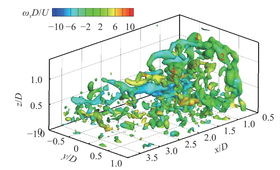
Fig. 17. The instantaneous isosurface of Q/(U/D)2 =13.5 colored by the streamwise vorticity ωxD/U
Figure 18a-18c exhibits the three scales of the 3D instantaneous Qi/(U/D)2isosurface with colored by the streamwise vorticity ωxiD/U. Here i represents the wavelet level. In the largescale structures of level 1, as shown in Fig. 18a, a large-scale arch vortex is clearly observed. Meanwhile a large-scale streamwise vortex with the negative sense of rotation is also extracted from the instantaneous flow field of Fig. 17. It goes through the center of arch vortex and develops to the downstream, which also dominates the flow structures at the downstream. As decreasing to intermediate-scale structures of level 2 in Fig. 18b, several fragments of arch vortices broken down at the downstream, and the intermediate-scale streamwise vortices and trailing vortices are extracted. In the small-scale structure of level 3 (with the central scale of 7.2 mm), as displayed in Fig. 18c, the relatively smallscale vortices become distribute and active in all measured region, especially near the wall. A part of them is contained in large- or intermediate-scale flow structures.
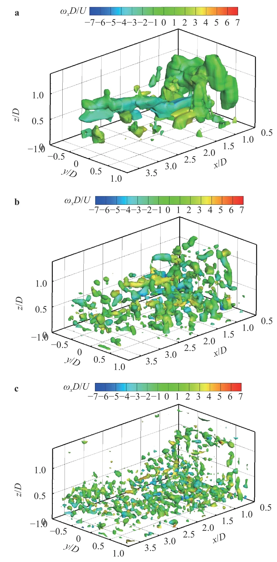
Fig. 18. The instantaneous multi-scale isosurface of Qi/(U/D)2 colored by the streamwise vorticity ωxiD/U
4.5 Combining wavelet transform and POD
The proper orthogonal decomposition (POD) is a common tool in the analysis of the complex flow field by extracting the dominant flow structures based on the mode energy distribution. However, wavelet transform is to decompose the flow structures based on frequencies or scales. Figure 19 shows the comparison of energy distribution between wavelet components and POD modes in a 2D symmetric triangle wake [37]. The first four wavelet components, as shown in Fig. 19a, contain 88%of the total kinetic energy. The wavelet components of level 1 and 2 make the largest contribution, accounting for 32% and 45%, respectively. It indicates that first two levels of wavelet components are apparently the uppermost and energy-containing structure, which is associated with the large-scale turbulent structure. However, the first two POD modes are most energetic and contain 73% of the total kinetic energy (first and second modes contribute 41% and 32%, respectively). The energy content of modes 3 and 4 reduces rapidly to 2.8% and 2.1%, and the energy contained in rest modes makes less contribution with increasing mode number. The energy concentration on first two modes suggests that the vortex shedding process can be linked to the first two modes.
It is clear that the energy distribution of first two wavelet components has similar tendency with first two POD modes, indicating they are capable of extracting dominating turbulent structures. However, the wavelet component of each level represents the turbulent structure characterized by frequency band widths, while the POD modes are classified based on the energy contained in each mode.
If we combine wavelet transform and POD to analyze the turbulent structures, the information on both of energy and scale can be obtained. There are generally the following two ways to perform. (1) The wavelet components of each scale are decomposed by using POD for analyzing the mode energy distribution of each wavelet component; (2) The mode components are decomposed by wavelet transform to clear the scale distribution of each mode.
Taking a boundary layer flow as an example, the velocity distributions were measured at Reτ= 235 by using 2D time-resolved PIV. The flow velocity fields were decomposed into a number of wavelet levels along time direction based on one-dimensional wavelet multi-resolution analysis [38]. Figure 20 shows the comparison of the energy distributions for the first 20 POD modes of wavelet level 3 to 10 and measured velocity data.Here the mode energy is normalized by the total energy of all the modes in the corresponding POD realization. In POD method,the mode energy is in descending order with the increase of mode rank, so the first a few modes are usually the most important ones.
The first POD mode of the measured PIV data takes up 18%of the total energy, while the first mode of wavelet level 1 takes up nearly 44% of the total energy, indicating a much more concentrated energy at wavelet level 1. This is reasonable because in the wavelet component of level 1 only large-scale structures are retained and they can be represented in just a few number of POD modes. With the increase of wavelet level, the first mode takes up less energy. At wavelet level 2-4, for example, the energy percentage for the first mode is 28%, 20%, and 15%, respectively. These can be considered as dominant energy containing modes at the corresponding wavelet level. At wavelet level 8,however, the energy percentage for the first mode drops to less than 1% of the total energy, and no dominant mode can be found.
The first POD modes of the streamwise velocity component at different wavelet levels are presented in Fig. 21, characterizing the most important coherent structures at each wavelet level.For example, the modes of level 1, 2 and 3 (Fig. 21a-21c) show the elongated structures that have streamwise length scales of several boundary layer thicknesses. The modes of levels 4, 5 and 6 are more likely to represent the coherent vortices (Fig. 21d-21f). In Fig. 21g, the mode shape of level 7 has much less coherence than those at the lower wavelet levels, where no predominant modes can be found. They tend to become more randomly and homogeneously distributed in the boundary layer. The above dominant POD modes at different wavelet level clearly reveal a cascade of scales in the turbulent boundary layer.
5 Conclusions
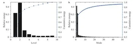
Fig. 19. Energy distribution. a Distribution of wavelet components; b distribution of POD modes.
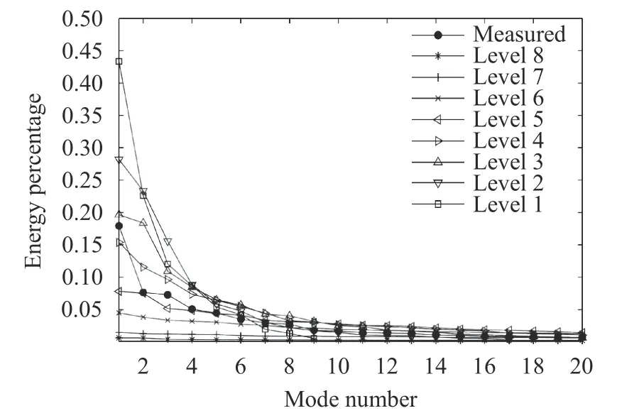
Fig. 20. POD mode energy for the measured and wavelet decomposed data. The mode energy is normalized by the total energy of all the modes in each POD realization
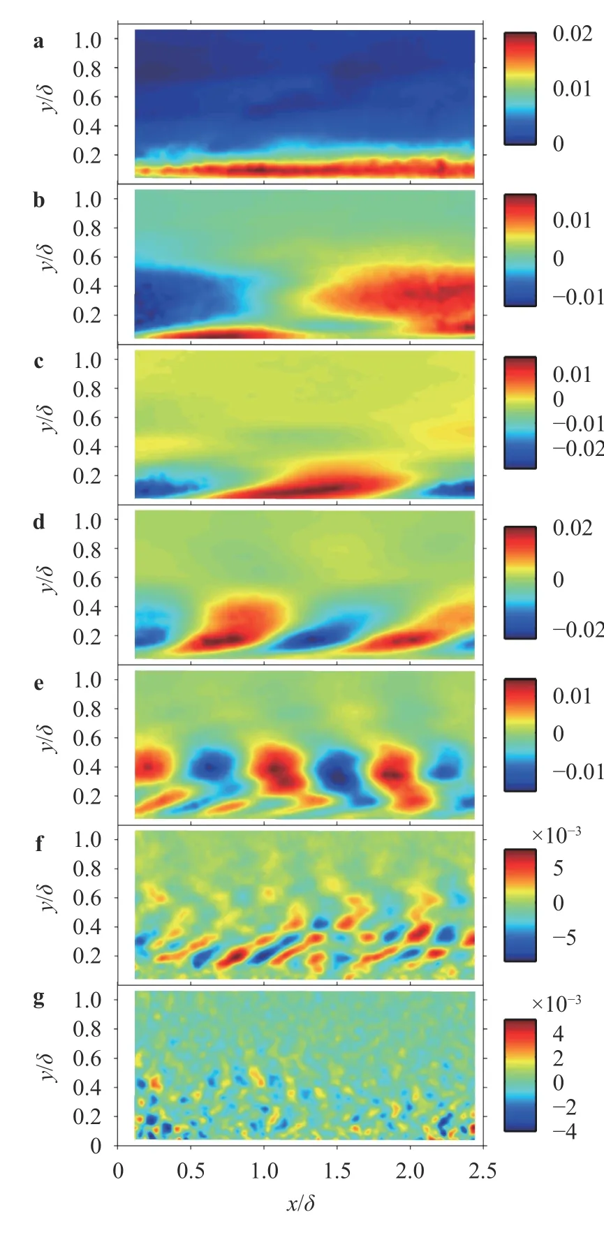
Fig. 21. POD modes of the wavelet components for the streamwise velocity u. a Level 1; b Level 2; c Level 3; d Level 4; e Level 5; f Level 6;g Level 7.
This paper describes the applications of wavelet transform on analyzing 2D and 3D turbulent wakes and turbulent boundary layer flows based on the hot-wire velocity data, 2DPIV and 3D tomographic PIV, after introducing background and theories of wavelet transform and wavelet multiresolution technique. It is exhibits that wavelet transform has become a powerful tool to analyze various multi-dimensional flows for both experiment and simulation. One of further works will focus on combing 3D wavelet transform and POD for analyzing 3D experimental data and obtain the 3D statistical characteristics of various scale flow structures.
Acknowledgement
The first author (AR) wishes to acknowledge the support given to him by Grant-in-Aid from the National Natural Science Foundation of China (Nos. 11721202 and 11772035). The second author (HR) gratefully acknowledges support from JSPS Research Fellowships for Young Scientists (2019~2022).
杂志排行
Theoretical & Applied Mechanics Letters的其它文章
- Editorial: Computational granular mechanics
- Construction of irregular particles with superquadric equation in DEM
- Prediction on dispersion in elastoplastic unsaturated granular media
- A block particle coupled model and its application to landslides
- Modified virtual internal bond model based on deformable Voronoi particles
- Modeling of deformation processes in rock massif in the vicinity of underground goafs considering the formation of discontinuity zones
