Modeling of deformation processes in rock massif in the vicinity of underground goafs considering the formation of discontinuity zones
2020-06-06MichaelZhuravkovShunyingJiAlegKanavalau
Michael Zhuravkov*, Shunying Ji, Aleg Kanavalau
a Department of Theoretical and Applied Mechanics, Belarusian State University, Minsk 220030, Belarus
b DUT-BSU Joint Institute, Dalian University of Technology, Dalian 116023, China
c State Key Laboratory of Structural Analysis for Industrial Equipment, Dalian University of Technology, Dalian 116023, China
d Research laboratory of information technologies and computer graphics, Belarusian State University, Minsk 220030, Belarus
K eywords:Block-layered structure Rock massif Stress-strain state Destruction and limit criteria Negative Poisson's ratio
ABSTRACT The construction of mechanical-mathematical model and numerical method for the deformation processes of rock massifs with goafs and underground structures is very complex and also important task in modern rock mechanics. In this study, the mechanical-mathematical model is developed for rock massif in vicinity of underground goafs considering the internal block-layered structure of the rock massif. A new constitutive model is introduced in this study to describe the negative Poisson's ratio for the lock-layered structure. Two types of defining equations systems for studying the state of a rock massif taking into account the block-layered structure are described.Finally, several examples are given using the present mechanical-mathematical model.
The relationship between the rock massifs deformation and theirs internal structure belongs to the actual problems of modern rock mechanics. Construction of relative mechanical-mathematical and numerical models for these deformation processes of rock massifs is one of the most important and complex task of rock mechanics.
In general, different structural states are generated in the rock massif of underground structures [1]. In discontinuity areas of the rock massif in the vicinity of underground workings, block structures can be formed [2]. Deformation of such structure occurs due to the sliding between blocks and their rotations. It is obvious that the resistance of the rock massif decreases during its deformation when a block structure is generated, but still remains finite. This phenomenon is characterized by the appearance of a descending branch in the stress-strain diagram. Obviously, the relationship between stresses and strains of the rock massif under this new state is different from the standard one.The relationship between stresses and strains is not unambiguous in the descending branch, but can be determined independently and separately from the basic laws of mechanics [3].
Since the formation of the block structure is generated at different scales with the similarity property, the present arguments are suitable for describing the processes both around single goafs and in areas with a large-scale system of underground structures.
Areas of discontinuity are formed in the rock massif when the shear stresses reach their limit values. The rock massif domain is divided by slip lines to form a block structure. This structure has its own durability τ*. The interactions between the blocks are characterized as slip and friction, as well as adhesion between adjacent blocks.
The following algorithm can be adopted to determine the block structure region, where the classical elastic relations cannot be suitable. A development approach for the mechanicalmathematical models can be introduced to study the deformation processes of rock massifs considering the presence of domains under the ultimate condition.
We accept the following assumptions [3, 4]. The directions of the principal stresses remain constant after the formation of underground cavities in the rock massif. The principal directions are related to the direction of gravity σgand directions perpendicular to the direction of gravity. When the shear stress exceeds its strength, slip sites appear in the considered area of the rock massif and the allocated volume is divided into blocks.
In accordance with the introduced assumptions, it is physically justified to assume the existence of limit values Tland Γlfor invariants of the strain Γ and stress T states or principal shear stresses and principal shear strains, which can be defined in the three-dimensional case as:In the case of 2D-deformation, we haveand
Thus, the invariants of the strain and stress can be written as[4]:

In the destruction areas, there are no connections between stresses and strains in the conventional sense. Therefore, the two criteria of Eq. (1) are independent in the general cases. In the fracture region, the stress and strain tensors are not coaxial. At the boundary points of the fracture region, the principal directions are rotated to take strains remain joint.
Therefore, to study the mechanical behavior of rock massifs in the deformation diagram at the post-peak stage, it is convenient to adopt the following three functions instead of the standard invariants as [5]:

where σnis the normal stress, μσis the Lode-Nadai parameter.
T he parameters T and σncharacterizes the massif strength at the site of force T13; the parameter μσcharacterizes the massif strength on the other two sites of T12and T23since it can be expressed as μσ=(T23-T21)/T.
In accordance with the observation on the independence of criteria in Eq. (1), Eq. (2) is insufficient to obtain complete information about the exhaustion of the bearing capacity of the rock massif in a particular situation. An additional condition of the principal strains ε1>ε2>ε3is adopted to study the post-peak in rock behaviors. Since the stresses and strains are not connected by a single-valued dependence in the post-peak state, it is necessary to introduce the following three new invariants to describe the irreversible deformations and fracture by:

So, the mechanical-mathematical formulation of the block structure in the rock massif includes the following equations.The criterion for the block structure formation: Γ=Γl; the strains εx,εy,εzsatisfy the Saint-Venant compatibility condition to describe the deformations in the area of rock massif discontinuity. The stresses are determined from a system including the equilibrium equations and the extreme condition T=Tl. The formulation above can be applied to study the deformation processes at various scales. The formulation above shows that the coincidence of the basic equations with the equations for the elastic-plastic state of the deformed body.
Considering the deformation process of the solid deformable block structure with various internal connections, the elements are individual blocks, and the links are interblock spaces.The essential portion is the choice of the blocks and interblock space behavior laws. Blocks can be considered as rigid or as elastic bodies. The interblock space can be considered as an elastic coupling between neighboring blocks. During the description of the deformation of the rock mass block structure, it is necessary to know the physical-mechanical properties of individual elements and interblock space, to determine the conditions of static or dynamic equilibrium of the blocks system at a given type of loading, and to set the sequence of loads application not only at each boundary point of the blocks set but also within the block structure at the interblock spacing [6].
In this study, a three-dimensional element of a layered rock massif in the form of a cube is considered. The layers are parallel to each other and have the same roughness. The planes of the layers are defined by the normal vector
Under the global coordinate system O-xyx, a local coordinate system with axes 1, 2, 3 is introduced. The direction of axis 2 is determined by the vector n2. Axes 1 and 3 are defined so that they are parallel to the layer planes and perpendicular to the Ox and Oy axes, respectively. Their directions are given respectively by vector n1and n3(as shown in Fig. 1), and can be written as:

Let the initial state of the body is under the action of compressive forces Nx, Ny, Nz, attracting layers to each other, and the body is in a state of static equilibrium. Then, for example, the normal load N2and the tangental loads N21and N23acting on the interblock spaces can be written as:

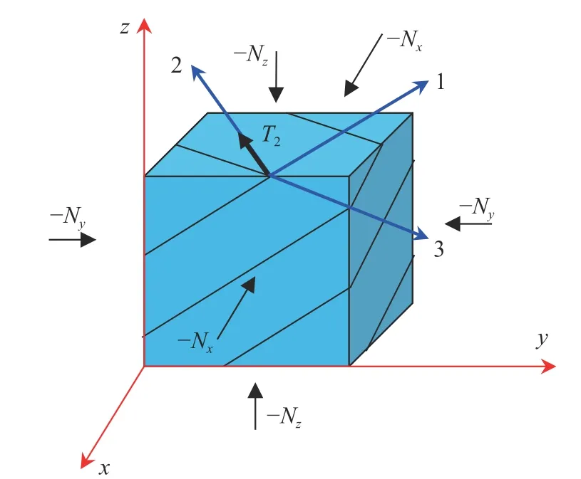
Fig. 1. Geometric interpretation of layered rock massif in the three dimensions

To determine the relationship between stresses and strains,the physical equations can be written as [6]:

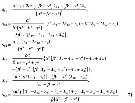
Thus, Eqs. (6) and (7) descript the deformation behavior of a rock massif with block structure in the three-dimensions when|σ2|≪N2. This means compared to the effect of N2on the shift process, the effect of σ2is negligible.
Compared with the classical deformable media, block structures perform non-standard mechanical properties, including the negative Poisson's ratio. Based on the knowledge of solid mechanics, the negative ν are possible under the condition μ >3K/2, here μ is the shear modulus and K is the bulk deformation modulus. This means the effective shear modulus of the medium is one and half times larger than its bulk deformation modulus. This situation possibly depends on the internal structure of the block medium. A block structure in a rock massif can be formed in such pattern. The rock massif continuity is kept,and its deformation occurs due to the sliding and rotations.
The phenomenon of dilatancy can be described as the behavior of a material with a negative Poisson ratio. Negative values of v were measured in experiments with samples of granite rocks containing microcracks. In addition, this anomaly was also observed in soils, such as porous sandstones.
We can consider a mechanical-mathematical model of a block medium with negative Poisson's ratio. The structural unit of the block medium is modeled by a system of elastic rod elements (as shown in Fig. 2a). The general relationship between the stress and strain tensors for such medium are obtained with equations relating the forces and displacements for this rod system. The behavior of the material can be described if you know the deformation law of the structural unit ABC (Fig. 2a). To construct the deformation law of the ABC fragment, we distinguish it as a body in equilibrium, while the bonds at the ends of rods are replaced by stretching Piand bending Qiforces (Fig. 2b).
Based on Eq. (6), the mechanical model of the block medium as shown in Fig. 2 can be represented as [8, 9]:

The components of the elastic modulus tensor σijare determined separately considering the equilibrium problems of the selected element ABC. Setting the value εxx, we define three coefficients of rigidity a11, a12, a13. Setting the value εyy, we define three coefficients of rigidity a13, a23, a33. Setting the value εxy, we define a12, a22, a23, respectively. Finally, the functionsandare obtained.
For the Poisson's ratio and Young's modulus, we have:

For example, for the values of the loading angle φ ≈0 and φ ≈π/2 when νxybecomes negative, we have:

where r=b/a is the ratio of the lengths of the vertical and inclined rods; Niand Miare the ABC element malleability, and can be written as:
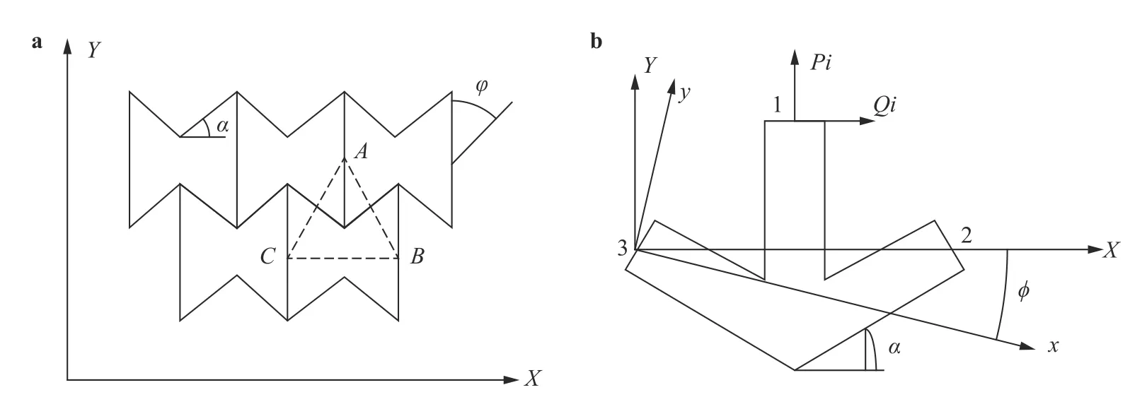
Fig. 2. Two-dimensional model of block structure of rock massif represented by a rod system and b corresponding structural elements.
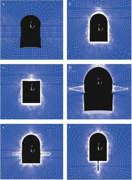
Fig. 3. Deformation state in the vicinity of a goaf in a layered rock massif. a The presence of clay layers in the sides of the goaf, b, c the presence of clay layers in the roof of the goaf, d the presence of inclined clay layers in the sides of the goaf, e the presence of clay layers and the compensation gaps in the sides of the goaf, f the presence of clay layer and the compensation gap in the bottom of the goaf.
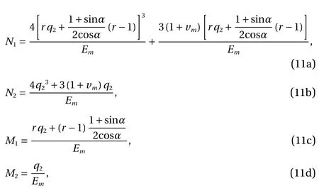
here, we have

where vmand Emare the Poisson's ratio and Young's modulus of rods material, Vfis the volume part of rods in the total volume of the element ABC.
The area of rock massif with single underground goaf is considered with the formulation above. The rock massif is a set of layers that are parallel to each other and inclined at an angle to the horizontal plane. Different layers are separated by interlayer space. Materials in the interlayer space are clays which are more malleable than rock. Therefore, we assume that the deformations in the massif occur mainly due to the deformation of the interlayer space.
Equations (6) and (7) were applied to describe the relationships between stresses and strains in 2D. We emphasize that Eqs. (6)-(10) are quite universal. Although they do not consider each layer separately, it is possible to take into account the main features of the layered massif deformation since the yielding strength λ1along the direction of the layers is different to the yielding strength λ2in the perpendicular direction. These equations make it possible to consider the characteristic directions of layering and weakening planes of massif.
The values λ1and λ2can be determined from physical experiments. However, it is not always possible to reproduce the deformation process of a rock sample in the laboratory, therefore,the elastic properties of massif can be known exactly. Due to the large error in experimental data, it is recommended to use the data of in-situ experiments and computer modeling results.
Case 1.To study the effect of the layers presence on the massif deformations around of single goaf, the compensation gaps approach is used here. The values of the main parameters of the goaf: the width -4.5 m, its height -3.0 m, the depth of the workings -800 m. For the rock layers, we set ρ=2300 kg/m3, ν =0.29,E=1.75 GPa, λ1=2/E(λ1=1/E), λ2=1/E , λ12=1/(2G),α=π/36=5°. Some simulation results are plotted in Fig. 3.
Case 2.To study the deformation state of the layered massif,the method of longwall mining was adopted to model the cavity with two large horizontal sizes considering the placement of waste rock in the cavity. The deformation processes in the waste rock strips was made by specifying the multilinear behaviour of the waste rock. The multilinear behaviour of a waste rock material is understood since it performs linear behavior. The law of waste rock strain can be expressed as:

where ε is the waste rock strain, %; ε0is the maximum strain of waste rock, %; q0is the compression parameter of the waste rock,MPa.
Equation (13) in the framework of the pseudoelastic model characterizes the stiffness of the waste rock material using the equivalent elastic modulus q0. The averaged compression parameters of the waste rock material can be set ε0= 24.83%, q0=14.7 MPa. The value of the elastic modulus at each iterative step is selected depending on the current value of the equivalent strain. The numerical model was constructed using the coupled FEM-DEM technology. Some results are presented in Fig. 4. The length of the excavation is 150 m.
Case 3.The modeling of the columnar pillar deformation and destruction.
Equations (6) and (7) are also used to describe the relationship between stresses and strains. We simulated the behavior of a columnar pillar under load. The sequence of model problems was considered when the load on the pillar increased. The properties of the material correspond to carnallite. Example numerical simulation results are presented in Fig. 5. The model showed adequate qualitative behavior that corresponds to rigid pillar.That is, for a quite long time, the pillar is in a solid and accumulates internal destruction (as shown in Fig. 5a). Then the pillar loses its bearing capacity and is destroyed (as shown in Fig. 5b and 5c).
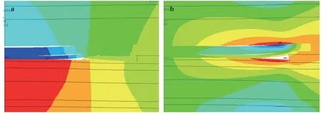
Fig. 4. Distribution of vertical displacements components in the massif around of longwall mining using the mining scheme a with a waste rock and b without a waste rock .
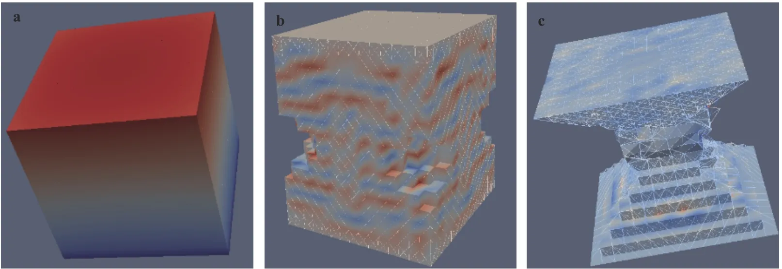
Fig. 5. Modeling of a columnar pillar deformation and fracture
Acknowledgement
This study is financially supported by the National Natural Science Foundation of China (Grant 11872136) and the Fundamental Research Funds for the Central Universities (Grants DUT19GJ206 and DUT19ZD207).
杂志排行
Theoretical & Applied Mechanics Letters的其它文章
- Editorial: Computational granular mechanics
- Construction of irregular particles with superquadric equation in DEM
- Prediction on dispersion in elastoplastic unsaturated granular media
- A block particle coupled model and its application to landslides
- Modified virtual internal bond model based on deformable Voronoi particles
- Application of multi-dimensional wavelet transform to fluid mechanics
