A block particle coupled model and its application to landslides
2020-06-06ChunFengShihaiLiQindongLin
Chun Feng*, Shihai Li, Qindong Lin
a Institute of Mechanics, Chinese Academy of Sciences, Beijing 100190, China
b School of Engineering Science, University of Chinese Academy of Sciences (UCAS), Beijing 100049, China
c International Centre for Numerical Methods in Engineering (CIMNE), Universitat Politècnica de Catalunya, Barcelona, Spain
Keywords:Finite element method Discrete element method Fracture Fragmentation Landslide
ABSTRACT To simulate the progressive failure of slope, a block particle coupled model is introduced. Particle oriented cell mapping (POCM) algorithm is used to enhance the search efficiency, and particlepoint, particle-edge, particle-face contact detecting method is adopted to establish contact pair between particles and blocks precisely. Strain softening Mohr Coulomb model with tensile cutoff is adopted for blocks, and brittle Mohr Coulomb model is used for particles. The particle-block replacement approach is used to describe the fracture and fragmentation process of continuum media. Once the cohesion or tensile strength of one block reaches zero, the block will be deleted,and particles are generated at the same place with all information inherited from the deleted block. Some numerical cases related to landslides demonstrate the precision and rationality of the coupled model.
The process of landslide involves the damage, fracture, fragmentation and movement of geological body. Finite element method (FEM) and discrete element method (DEM) are two effective numerical methods to simulate such problems.
FEM is good at simulating continuous problems, such as elastic and plastic deformation of soil and rock slope under static or dynamic loads [1, 2]. In this method, the macro mechanical parameters and constitutive laws obtained from experiments will be used. With the development of experimental technology,the macro mechanical parameters of various materials can be measured accurately. When use FEM to simulate fracture or fragmentation problems, some numerical problem will happen,although there are lots of numerical ways (death element method [3], adaptive remeshing [4, 5], extended finite element method (XFEM) [6, 7], etc. to deal with it.
Particle DEM is widely used to simulate the progressive failure and movement of slope [8, 9]. The region in particle DEM is discretized by rigid particles (spheres or ellipsoids, et al) and particle contacts. In particle DEM, the contacts are used to represent the deformation and crack, and the particles are used to calculate the evolvement (translational and rotational movement). When using particle DEM, the relationship between micro parameters (such as stiffness, damp, strength) and macro parameters (such as elastic modulus, Poisson ratio, and strength) are difficult to established, sometimes hundreds of numerical cases are needed [10, 11].
An alternative method is to couple FEM and particle DEM together, so the advantage of FEM and particle DEM will be assembled. Oñate and Rojek [12] suggested thus combined method, and a contact algorithm considering the contribution of rotation was adopted between FEM and DEM interface. Rojek and Oñate [13] introduced an overlapping algorithm to deal with the force transmission between FEM and DEM based on Ref. [12],and 0-1 interpolation function was used in the overlapping zone.
By combing the advantage of FEM and particle DEM together, a block particle coupled model with replacement approach is proposed in this paper. The contact detect algorithm and constitutive laws related to blocks and particles are introduced.Then the particle-block replacement approach is discussed in detail. Some numerical cases related to landslides are demonstrated.
To find neighbours between particles and blocks efficiently and robustly, two steps should be taken generally, namely global contact searching and local contact resolution.
The purpose of global contact searching is to enhance the searching efficiency by dividing the particles and blocks into some independent parts based on the space position of each particle. The particle oriented cell mapping (POCM) algorithm is adopted here.
In POCM algorithm, the axis-aligned bounding box (AABB)for each particle and each block are created first. Then the particles and blocks are mapped to background cells based on the AABB boxes. When execute contact searching, each particle is considered as a detecting master, and the target blocks are checked from the cells which the AABB of master particle located in. POCM is a linear complexity algorithm, very effective for large simulations, and not sensitive to the spatial distribution of objects.
The purpose of local contact resolution is to find the neighbours and contact position for each particle and block accurately. Generally, blocks in 3D consists of points, edges and faces,while blocks in 2D is formed by points and edges. So, there are three contact patterns between particles and blocks, which are particle-point contact, particle-edge contact and particle-face contact, respectively. For 3D problems, all the three patterns need to be checked. However, for 2D problems, only particlepoint check and particle-edge check is needed.
The contact state between particle and point of block could be described as

where dijmeans the distance between particle i and point j of one block, Riis the radius of particle i, tol denotes the contact tolerance.
Here, tol is a global parameter, which is suitable for all contact patterns. Generally, Eq. (2) is used to select a suitable value for a specific numerical model. In this paper, the tol is set to zero.

where dminis the minimal diameter of particles, and Lmindenotes the minimal characteristic length of blocks.
If one particle contacts with an edge (Fig. 1), two conditions should be satisfied at same time. They are
where d means the distance between center of particle p and the edge ij, R is the radius of particle p, Vipis the position vector pointing from point i to the center p, n denotes the vector pointing from k to p, k is the projection point of p lies in edge ij,Vkidenotes the unit vector pointing from k to i, and Vkjdenotes unit vector pointing from k to j.
The weighted coefficient of point i and j in Fig. 1 could be calculated by

where dij, dik, and djkmean the distance between point i and j, i and k, j and k, respectively.
For checking particle-face contact pattern, the local coordinate system of the face should be established first. All the global coordinates of vertexes on the face of block and coordinate of particle (Fig. 2) should be transformed to this local coordinate system.
The distance between particle and block face could be calculated by

where xp-3and xi-3is the third component of local coordinate of particle p and vertex i, respectively.
If particle contacts with a block face Eq. (7) should be satisfied first

The local position vector of projection point m could be expressed as

The topological relationship between the projection point m and the block face could be detonated by

where Vmiis the unit vector pointing from m to i, and the same as Vmj, Vmkand Vml. If point m locates inside the block face, then Eq. (10) should be satisfied for any composition of i, j, k

If Eqs. (7) and (10) are satisfied at same time, the particle p and the block face ijkl contact with each other.
An elastic-plastic model with strain softening effect is proposed to describe the linear elastic stage and strain localization stage of the blocks.
In linear elastic stage, Hooke’s law is adopted

Fig. 1. Point-edge contact
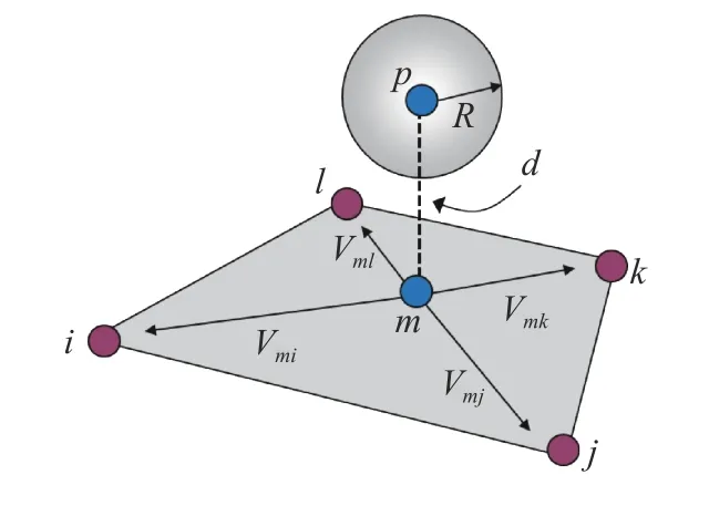
Fig. 2. Contact detection between particle and block face

where σijand εijdenotes stress and strain tensor, θ means bulk strain, K and G mean bulk modulus and shear modulus, and δijis Kronecker delta.
In strain softening plastic stage, the incremental method is adopted, and softening Moh-Coulomb criterion with tensile cutoff is used.
Three principal stresses σ1, σ2and σ3will be calculated based on trial stress tensor, and then failure status of this block is determined by

where σs(t), φ, σt(t) denote cohesion, inner friction angle and tensile strength in current step. Nφ, αp, and σpare constants,expressed as

If fs≥ 0 and h ≤ 0, shear failure will happen, and if ft≥ 0 and h >0, tensile failure will appear.
Simultaneously, according to the equivalent shear plastic strain and bulk plastic strain in current step, the new cohesion and tensile strength used in next step is calculated by

where, σs(t+Δt) and σt(t+Δt) denote cohesion and tensile strength in next step, Δt means time step, σs0and σt0are cohesion and tensile strength at initial state. γpand θpare equivalent shear plastic strain and bulk plastic strain in current step, γuand θurepresent the ultimate bulk plastic strain and ultimate shear plastic strain.
A brittle Mohr-Coulomb model with tensile cutoff is adopted for particle-particle contacts and particle-block contacts.
Firstly, relative incremental displacement between particles,or between particles and blocks in global coordinate system should be calculated.
Then the relative incremental displacement vector in local coordinate system is obtained

where T is the transform matrix.
The normal and tangential relative incremental displacement at contact is calculated by

where, Δdunand Δdusdenote normal and tangential incremental displacement, respectively. Δdu1, Δdu2, Δdu3are three components of local incremental contact displacement vector Δdu.
An incremental explicit scheme is used to compute trail normal force and tangential forces

where Fn, Fs1and Fs2denote normal force (negative in tension)and two component of tangential force, Knand Ktare normal and tangential stiffness.
The magnitude of tangential force could be computed by

Equations (19) and (20) is used to judge the tensile and shear failure and correct the normal and tangential contact force.
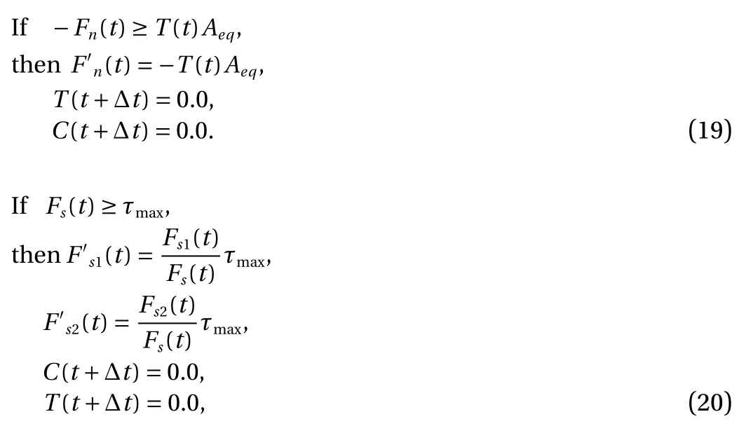
where Aeqis the equivalent contact area, T0, T(t) and T(t+Δt)denote the tensile strength of contact in initial state, current step and next step. C0, C(t) and C(t+Δt) denote the cohesion of contact in initial state, current step and next step. τmaxis expressed as

where φ denotes inner friction angle of contact.
To simulate the fracture and fragmentation phenomenon of continuum media under different loads, a particle-block replacement approach is suggested.
At the very beginning, the numerical model is filled by blocks. If one block’s tensile strength or cohesion reaches 0, the element will be killed, and the particles will be generated at the same place. The particle information will be inherited from the deleted element, and then the block-particle contact force will be calculated. By the deletion of elements and generation of particles, the initiation and propagation of crack could be simulated, and Fig. 3 shows the process from block changing to particles.
There are two ways to create particles (Fig. 4). One is generating single particle in the deleted block, and the other is creating random distributed particle cluster with little overlapping.
In the first method, the center of particle should coincide with the centroid of block, the radius is the shortest distance from particle center to the sides of block, and the mass is equal to the corresponding block.
In the second approach, the initial packing density is controlled by the particle number, particle distribution mode, and the expectation and standard deviation of radius of particles. In this paper, uniform distribution pattern with 30% standard deviation coefficient is used. Generally speaking, particle number is related to some parameters of the block, such as strain ratio,peak stress, strength, and so on. However, to simplify the simulation, a fixed particle number is adopted for each block in this paper. Equation (22) is used to calculate the average radius.

where Abdenotes the area of block in 2D, and Vbmeans the volume of block in 3D, and N represents the number of particle needed to be created.
In this paper, the centroid of the particle clusters isn’t controlled to coincide with the centroid of the deleted block.However, due to the large number of randomized particles in the cluster, these two centroids are more or less the same.
When creating particle cluster, the mass conservation needs to be met, and Eq. (23) is adopted to calculate the mass for each particle.

where miand Simean the mass and area (volume) of particle i,Spis the total area (volume) of all particles in the cluster, and Mbdenotes the mass of the block.
After creating the particles, the elastic parameters, strength,velocity and contact forces of particles should be inherited from deleted block.
The normal and tangential stiffness between two contacted particles could be calculated by

where Kn-pp, Kt-ppare normal and tangential stiffness between particles, E and G are elastic modulus and shear modulus of block. Ac-ppis contact area between two particles, which could be obtained by

Dijis the contact distance between two particles, which could be computed by

where Riand Rjare the radius of particle i and j, Oijmeans the overlap width between two particles.
The normal and tangential stiffness between particles and blocks could be calculated by

where Kn-pb, Kt-pbare normal and tangential stiffness between particles and blocks, R means the radius of the particle. Ac-pbdenotes contact area, which could be obtained by

The strength parameters of particle-particle contact and particle-block contact are the same as the ones of the deleted block. So, the cohesion, tension, and inner friction angle of contacts could be inherited from the corresponding block directly.
The velocity and contact force of particle also should be inherited. The velocity could be calculated by Eq. (29), and the contact force could be calculated by Eq. (30).


Fig. 3. Process from block changing to particles

Fig. 4. Two particle creation ways

When some blocks change to particles, block and block contacts will appear, and semi-spring & semi-edge combined contact model will be adopted to detect the contact and compute the contact force [14].
A triangular block is created with one internal angle 30°, and one particle with the radius 0.5 m is placed on this block (Fig. 5).The direction of gravity is downward, and the value is -9.8 m/s2.The density of the particle is 2500 kg/m3, the elastic modulus is 30 GPa, and the Poisson's ratio is 0.25. The block is only used to provide contact boundary, so the block is totally fixed.
Numerical cases only considering sliding are (without rotation) executed first. The sliding curves with different friction angles are shown in Fig. 6, and the analytical solution is computed by Eq. (31). From this figure, with the increase of time,sliding distance increases gradually, the greater of the friction,the slower of the sliding. When friction angle exceeds 30° (slope angle), the particle will remain stationary. Numerical results coincide well with theoretical ones, which demonstrate the accuracy of contact detecting algorithm and sliding calculation

Numerical cases both considering sliding and rotation are executed then, and in these cases, the rolling friction is not considered. The sliding curves with different friction angle are shown in Fig. 7. In this figure, when friction angle exceeds 10°,sliding curves are almost the same, even if the friction angle is far greater than slope angle. When friction angle equals 0 degree,due to without moment, only sliding occurs, and the sliding curve is the same as the one in Fig. 6.
A rock uniaxial compression numerical test is executed to validate the precision. Single particle creating approach is adopted in this case when one block reaches the critical state (the tensile strength or cohesion reaches 0). The size of rock sample is 0.1 m × 0.2 m, which is formed by 7580 triangle FEM elements.The material parameters of the rock sample are elastic modulus 30 GPa, Poisson ratio 0.25, initial cohesion 3 MPa, initial tensile strength 1 MPa, friction angle 45°, and dilation angle 10°. Ultimate value of equivalent shear plastic strain and maximum tensile plastic strain are 1% and 0.1% respectively. In Fig. 8, Ytype shear failure could be clearly observed, and the peak stress of numerical simulation (14.6 MPa) is the same as the analytical one (14.5 MPa) obtained
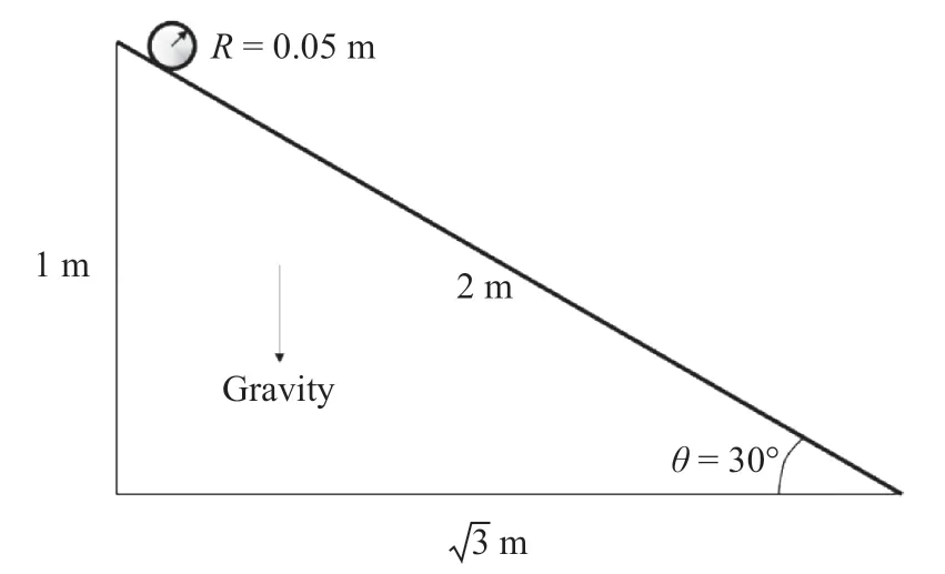
Fig. 5. Model of particle and block
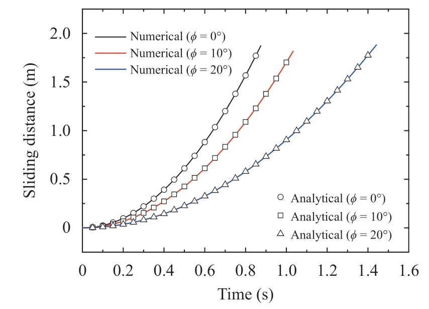
Fig. 6. Sliding distance versus time with different friction angle φ(without rotation)
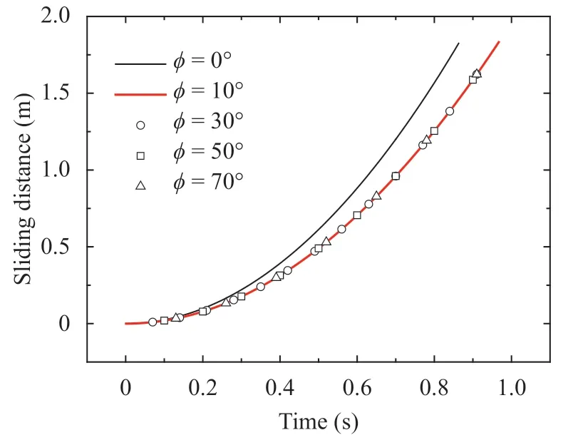
Fig. 7. Sliding distance versus time with different friction angle φ(with rotation)
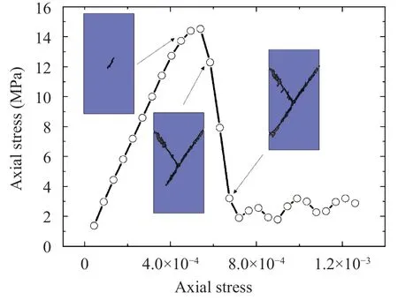
Fig. 8. Axial stress and strain relationship and failure pattern at typical state
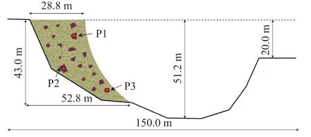
Fig. 9. Numerical model of RSA slope
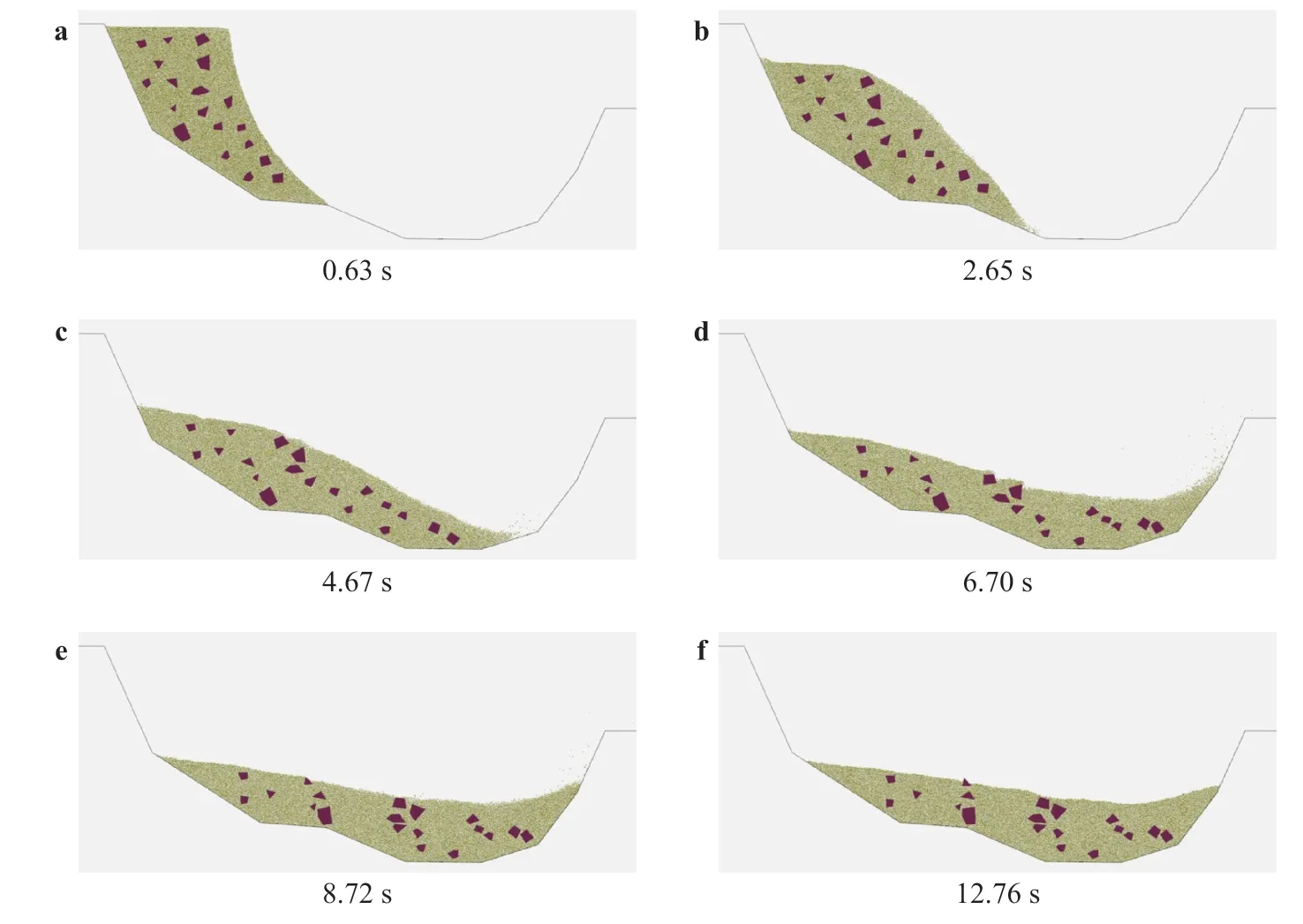
Fig. 10. Failure process of RSA slope

A generalized rock-soil aggregate (RSA) slope is established first (Fig. 9), and 19 rock blocks with 728 triangular FE elements,and 23408 particles are created. Linear elastic model is adopted for rock blocks, with the density 2500 kg/m3, Young's modulus 10 GPa, and Poisson's ratio 0.25. A brittle Mohr Coulomb model with tensile cutoff is applied on soil, with the density 2000 kg/m3,Young's modulus 0.1 GPa, Poisson's ratio 0.3, cohesion 10 kPa,tensile strength 10 kPa, and inner friction angle 20°. Three monitoring point is set on blocks, namely P1, P2 and P3.
Due to the low strength of soil, failure firstly occurs in particles. With the movement of particles, the rock blocks begin to move. At very beginning, translation is the main movement mode of block. After about 3 minutes, rotation gradually appears. After 10 minutes, the sliding finished, with the maximal sliding distance 90 m approximately. From Fig. 10, there are large number of contacts between particles and particle, and between particles and blocks. The numerical results demonstrate the robust and accuracy of the contact detection algorithm proposed in this paper.
The time history of displacement magnitude of P1, P2, and P3 is shown in Fig. 11. From this figure, the movement of the rock block experiences three stages, acceleration stage, constant speed stage and deceleration stage. After 8.5 minutes, these three blocks are stable basically.
A novel bedding rock slope model (Fig. 12) with 145 triangular blocks are created. Particle cluster creation way is adopted,and when one block reaches the critical state, 100 particles will be generated. Strain softening Mohr Coulomb model with tensile cutoff is adopted, with the density of slide body 2500 kg/m3,elastic modulus 30 GPa, Poisson's ratio 0.25, cohesion 1 MPa,tensile strength 1 MPa, inner friction angle 30°. The deformation of sliding bed is ignored, and rigid model is adopted. The inner friction angle between slide bed and slide body is set as 15°, with zero cohesion and tensile strength.
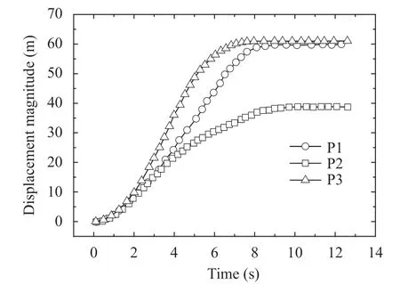
Fig. 11. Displacement magnitude history of P1, P2 and P3
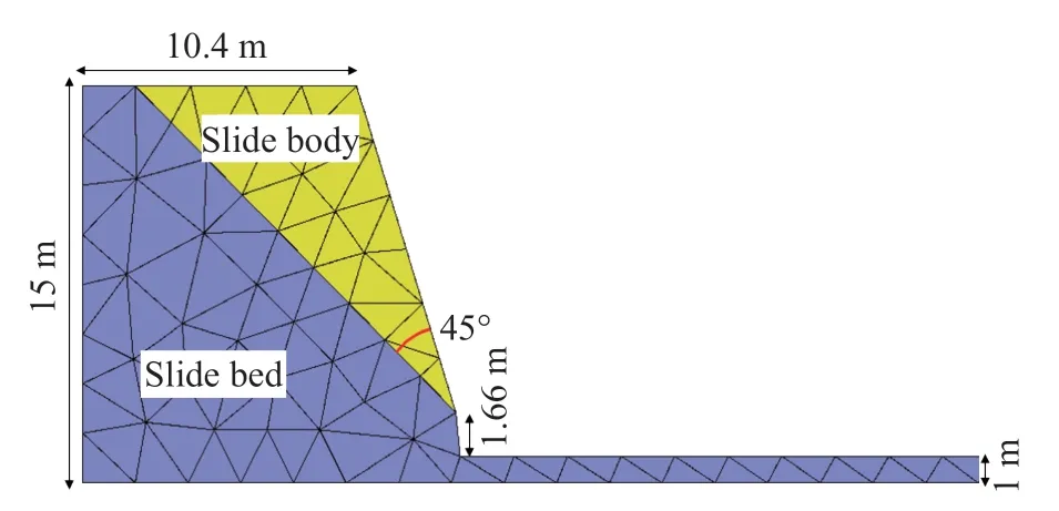
Fig. 12. Numerical model of bedding slope
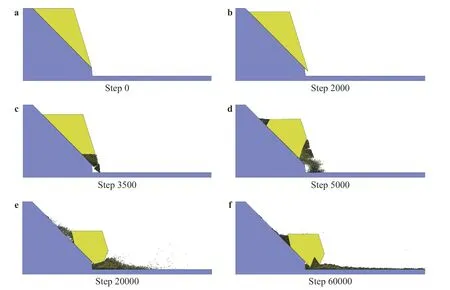
Fig. 13. Fragmentation and movement process of bedding rock slope
The fragmentation and movement process of bedding rock slope is shown in Fig. 13. From this figure, with the sliding of rock mass, the block gradually breaks into a series of small pieces (particles). The particles and blocks are mixed together forming the macro flow. The numerical results show the rationality of particle-block replacement approach suggested in this paper.
The particle block coupled model combines the advantage of FEM and DEM together. The deformation and plastic flow are simulated by FEM, crack propagation, friction and movement is simulated by particle DEM. According to the deletion of FEM element and creation of DEM particle, the initiation and propagation of crack in geological body could be simulated.Some numerical cases related to landslides are demonstrated to show the validity and accuracy of the model.
However, the model requires further more study, such as the contact constitutive law between particles and blocks, the replacement algorithm from blocks to particles, et al.
Acknowledgement
The work was supported by the National Key Research and Development Project of China, the Ministry of Science and Technology of China (Grant 2018YFC1505504).
杂志排行
Theoretical & Applied Mechanics Letters的其它文章
- Editorial: Computational granular mechanics
- Construction of irregular particles with superquadric equation in DEM
- Prediction on dispersion in elastoplastic unsaturated granular media
- Modified virtual internal bond model based on deformable Voronoi particles
- Modeling of deformation processes in rock massif in the vicinity of underground goafs considering the formation of discontinuity zones
- Application of multi-dimensional wavelet transform to fluid mechanics
