Effective enhanced model for a large deformable soft pneumatic actuator
2020-05-06QipingXuJinyangLiu
Qiping Xu · Jinyang Liu
Abstract Soft pneumatic actuators have been widely used for implementing sophisticated and dexterous movements, due to numerous fascinating features compared with their rigid counterparts. Relatively speaking, modeling and analysis of an entire soft pneumatic actuator considering contact interaction between two adjacent air chambers is extremely rare, which is exactly what we are particularly interested in. Therefore, in order to establish an accurate mechanical model and analyze the overall configuration and stress distribution for the soft pneumatic actuator with large deflection, we consider the contact interaction of soft materials rather than hard materials, to produce an effective enhanced model for soft contact of a large deformable pneumatic actuator. In this article, a multiple-point contact approach is developed to circumvent the mutual penetration problem between adjacent air chambers of the soft actuator that occurs with the single-point contact approach employed in linear elastic rigid materials. In contrast to the previous simplified rod-based model that did not focus on contact interaction which was adopted to clarify the entire deformation of the actuator, the present model not only elaborates nonlinear large deformation and overall configuration variations, but also accurately delineates stress distribution law inside the chamber structure and the stress concentration phenomenon. By means of a corresponding static experiment, a comparison of the simulation results with experimental data validates the effectiveness and accuracy of this model employing a multiple-point contact approach. Excellent simulation of the actual bending deformation of the soft actuator is obtained, while mutual penetration is successfully circumvented, whereas the model with single-point contact cannot achieve those goals. Finally, as compared with the rod-based model, the results obtained using the proposed model are more consistent with experimental data, and simulation precision is improved.
Keywords Soft contact · Large deformable pneumatic actuator · Mutual penetration problem · Multiple-point contact approach · Stress distribution
1 Introduction
Compared with traditional rigid robots, soft robots have intrigued many researchers owing to advantages including strong bendability, high security, and excellent environmental adaptability [1]. The soft pneumatic actuator is a type of soft robot that can be used to achieve various sophisticated motions, for instance, grasping a fragile raw egg, passing through a narrow space, and avoiding obstacles. These robots are composed of incompressible hyperelastic materials that obey nonlinear constitutive laws such as dielectric elastomers, silicone or hydrogels [2-4]. In contrast, rigid counterparts consisting of conventional metal materials cannot perform those sophisticated tasks with ease. Over the past several years, soft pneumatic actuators have been rapidly gaining popularity. Most previous studies have focused on the design and fabrication of different actuators along with a series of related experiments such as grabbing [5], crawling [6], or jumping [7].
Over the past 20 years, George Whitesides and his group at Harvard University [8, 9] have made many soft pneumatic actuators that are capable of realizing diverse types of actions such as stretching, bending, twisting, or a combination of them. The study by Wang et al. [10] proposed a programmable design to enable pneumatic actuators to realize coupled bending and twisting actions in threedimensional space, and then conducted different actuation experiments and finite element analysis to demonstrate the deformation characteristics of the actuators by altering the chamber angle. In another study, Connolly et al. [11] analyzed in detail how the deformation of fiber-reinforced soft actuators was affected by adjusting the fiber angle, and they performed a series of finite element simulations to examine the relationship between fiber angle and actuator deformation. In a work by Moser et al. [12], the authors constructed a snake-like elastomeric manipulator to achieve complex helical motions and illustrated a kinematic method to confirm different deformation modes of the continuum manipulators. These studies have shown that soft pneumatic actuators not only accomplish simple basic two-dimensional movement patterns, but they also achieve three-dimensional composite locomotion modalities to realize the goal of dexterous operations.
However, the modeling and analysis of these actuators is a challenging task considering contact interaction between two adjacent air chambers. Thus it is essential to determine the appropriate method to address such modeling problems.
In a recent work, Zhou et al. [13] elaborated three types of point contact modes and used curvature profile control for grasping of objects. Subsequently, Payrebrune and O’Reilly [14, 15] put forward a rod-based model with a five-parameter constitutive relationship to predict the dynamic features of a pneumatically actuated soft actuator, and inspected the relation between pressure and intrinsic curvature and the moment-curvature relations using the finite-element model. All in all, the common feature of these soft actuators is their pneumatic network construction, in which silicone elastomers are embedded in a series of interconnected air chambers. However, the mutual contact interaction between two adjacent air chambers has not been considered so far in the published literature.
To the best of our knowledge, most previous works have concentrated primarily on experimental study, and only a few articles have focused on modeling work [16, 17]. Studies dealing with the modeling and analysis of the entire soft pneumatic actuator considering contact interaction between two adjacent air chambers are scarce, and this is exactly what we are specifically interested in. Although the mutual contact phenomenon of multiple connected air chambers in an inflated pneumatic actuator have been clearly observed in previous experiments, there is a lack of research on how adjacent air chambers interact with each other. The problem of achieving sufficient bending deflection considering contact interaction is still unanswered.
This paper is organized as follows. First, in view of the soft contact between two adjacent air chambers, modeling and analysis of the soft pneumatic actuator with large bending deformation is carried out using an effective enhanced model with multiple-point contact approach, which is employed to elucidate the contact behaviors of the soft actuator. Next, by introducing air pressure and contact interaction into two adjacent air chambers, generalized elastic, pressure, and contact forces are derived, and the static equilibrium equations of the actuator are established, while the process for solving the static bending deformation is presented through a flow chart. The apparent deformed configurations and von Mises stress distributions are clarified to determine the mechanical properties. Finally, the beneficial effect of the proposed model on the large deformation of the soft actuator is illustrated by comparing the simulation results with experimental results.
2 Soft pneumatic actuator
2.1 Kinematic description
In this paper, an enhanced model with a multiple-point contact approach is proposed to reveal the internal contact phenomenon and predict the mechanical properties of a soft pneumatic actuator, as shown in Fig. 1a.
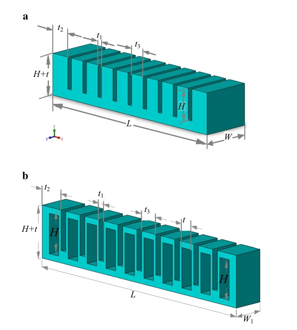
Fig. 1 Soft pneumatic actuator. a Whole soft pneumatic actuator, b half of the soft pneumatic actuator
Details regarding the fabrication process of the soft pneumatic actuator, which is composed of a battery of chambers, can be found in Ref. [18]. For the sake of simplicity, in order to display the internal structure of the soft pneumatic actuator and consider the symmetry of the geometric construction, half of two air chambers of the soft pneumatic actuator are taken for in-depth study. The internal construction of half of the soft pneumatic actuator and half of two adjacent air chambers is shown in Fig. 1b, respectively.
These chambers are filled with air, and the specific dimensions of the soft actuator in the following figures are L = 82 mm, W = 20 mm, H = 13 mm, l = 18 mm, W1= 10 mm, t = 4 mm, t1= 2 mm, t2= 8 mm, t3= 6 mm.
In the following, half of two air chambers is first modeled using the proposed model based on three-dimensional (3D) solid elements to exhibit internal deformation and mechanical characteristics. The 3D solid element is a hexahedron element with either a flat or curved surface. Each node of the element has three translational degrees of freedom. Consequently, the solid element can achieve arbitrary deformation in all three directions.
The displacement of an arbitrary point on the solid element is written as

2.2 Virtual work of the internal force
The total strain energy in Yeoh model for each solid element of the soft actuator is expressed as [19]


Defining Nx=∂N∕∂x , Ny=∂N∕∂y , Nz=∂N∕∂z ,and sub-
stituting the position vector r into Eq. (3), then I1can be denoted as

For the solid element with linear interpolation in transverse directions, the selective reduced integration (SRI) method is adopted to avoid the volumetric locking problem [21]. In the total strain energy of Yeoh model with SRI, the first term which does not take the volumetric effect into account is fully integrated in three directions, whereas the second term which allows for the volumetric behavior is computed provided that the entire volume is constant. Then, Eq. (2) is denoted as

where GC=detand C is center point of solid element.
Defining rcx=∂r∕∂x(x=xC) , rcy=∂r∕∂y(x=xC) , rcz=∂rC∕∂z(x=xC) , the determinant of GCis deduced as

The variation of I1in Eq. (4) takes the form

Since

where G=det (G) , and G=[∂r∕∂x ∂r∕∂y ∂r∕∂z] is the deformation gradient tensor; κ is the penalty factor, which should be selected to be sufficiently large to satisfy the incompressibility condition G=1 ; C10, C20, C30are the material constants of Yeoh model, which can be determined by uniaxial tensile tests [19, 20]; I1is the first invariant of the right Cauchy-Green deformation tensor, which is given by
The variation of GCin Eq. (6) is derived as

The virtual work of the internal force is obtained as

Substituting Eqs. (7) and (9) into Eq. (10), the virtual work of the internal force has the following formula:

where the element elastic force vector is written as

in which

where Ncx=∂N∕∂x(x =xC) , Ncy=∂N∕∂y(x=xC) , Ncz=∂N∕∂z(x=xC).
2.3 Virtual work of the air pressure force and contact force
The virtual work of the pressure force induced by the air pressure is formulated as

where p is the air pressure, np, S are the unit normal vector and the surface area of the element subjected to the air pressure, respectively, andthe displacement vector in the Cartesian coordinates, which is given bywhereis the shape function matrix of the rectangular surface element, and qepis the element coordinate vector of the surface element subjected to the air pressure.
The element pressure force vector is yielded as

In this investigation, the friction is neglected, and it is assumed that a given contact point is always uniquely projected onto arbitrary surfaces. Single-point contact and multiple-point contact approaches are employed to calculate the element contact force, respectively. In the local search procedure, the closest point projection must be found in order to solve the contact force between adjacent chambers [22]. Figure 2 illustrates the closest-point projection in the spatial coordinate system, where s is a slave point in a slave body, and m is a master point in a master body, which is the projection of the slave point s from the slave body onto the master body, nmis the unit normal vector of the contact surface at the master point, rsis the global position vector of the slave point s, and rmis the global position vector of the master point m, which is parameterized as
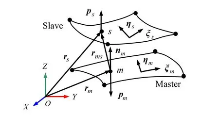
Fig. 2 Closest point projection

Defining rms=rs-rmas the relative position vector of point s with respect to the master point m, the closest point projection procedure leads to following minimum problem:

The solution of Eq. (17) can be obtained by solving the following formula:

The final result is obtained according to the stop criteria for the iteration process with a given tolerance ε = 10-6.
The natural coordinates ξm, ηmof the projection point m of the master element can be obtained by solving Eq. (19). The unit normal vector of the contact surface of the master element is then given by nm=n/|n| , in which w=
Defining d as the dot product of the relative position vector rmsand the normal vector nm

It is obvious that for d > 0, the contact traction pm=ps= 0; for d < 0, the contact pressure takes the form

where δ is the value of penetration, which is given by δ =|d| , and k is the contact stiffness. The contact traction exerted on the master and slave surfaces can be expressed as

The virtual work of the contact force is denoted as

The element contact force vectors of the master and slave elements are formulated as

Single-point contact refers to the technique in which the center point of a slave element is in contact with the center point of the corresponding master element, and multiple-point contact refers to the technique in which multiple Gaussian points of a slave element are in contact with the projection points of the corresponding master element. To improve precision, 4 × 4 Gaussian points are adopted. Thus, the contact area is approximated as a set of integration points that penetrate the corresponding master segment.
2.4 Static equilibrium equations

Based on the virtual work principle, the variational equation of the soft pneumatic actuator is derived as where nk is the number of solid elements, np is the number of elements subjected to air pressure, and nc is the number of contact pair elements.

where Qk, Qp, and Qcrefer to the global generalized elastic force vector, the global generalized pressure force vector, and the global generalized contact force vector, respectively, which are expressed as
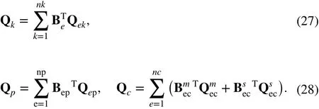
From the above, with respect to half of the cantilevered soft pneumatic actuator with constraint equation Φ=0 , the equilibrium equations along with the constraint equations can be represented as

where λ is the Lagrange multiplier vector.
The numerical integration technique referred to as Gaussian quadrature can be adopted using MATLAB software to compute the contact force and the elastic force in the computer implementation process.
The nonlinear Eq. (29) is solved using the Newton-Raphson iterative method; the (i + 1)th step and the ith step have the following relation in iterative computation

where

The iteration terminates when the norm ofis less than a designated adequately small positive quantity, i.e.and ε is the error tolerance. In the example, ε = 10-6.
Compared with the model with single-point contact, the present model may have larger mesh size (that is, fewer elements); thus less computational time is required, while accuracy is improved.
The complete process for solving static bending deformation can be presented in a flow chart, shown in Fig. 3. The key steps are as follows.
Step 1: Determine the material constants C10, C20, C30of Yeoh model using the uniaxial tensile test, then input the shape functions Ni(ξ η ς) , the constant coefficients including penalty factor κ and contact stiffness coefficient k, the initial nodal displacement q0, initial Lagrange multiplier λ0, and initial air pressure p0.
Step 2: The nodal displacement q and the Lagrange multiplier λ are given by q0, λ0, respectively.
Step 3: Compute the first invariant I1, the determinant GCof the deformation gradient tensor GC, and the strain energy UY.
Step 4: Based on the virtual work principle, compute the element elastic force vector Qek, the element pressure force vector Qep, and the element contact force vectors of the master element and the slave element
Step 5: Using an assembling procedure, compute the global generalized elastic force vector Qk, the global generalized pressure force vector Qp, the global generalized contact force vector Qc,and
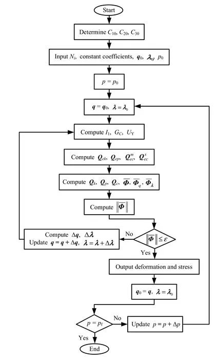
Fig. 3 Flow chart for solving bending deformation
Step 7: Assign the updated nodal displacement q and initial Lagrange multiplier λ to q0and λ0as the initial nodal displacement and the initial Lagrange multiplier.
Step 8: If the air pressure does not reach a final value of pf, then update p=p+Δp ; repeat Step 2 through Step 7 until final air pressure pfis attained, then finish.
3 Numerical simulations
3.1 Contact analysis of two chambers
In order to elucidate and observe the large internal deformation and all of the configuration variations of two adjacent air chambers, the contact interaction status between two adjacent chambers is disclosed, adopting the developed models with single-point contact and multiple-point contact separately when the air pressure is given by p = 35 kPa. The influence of gravitational force is neglected, the material constants of the Yeoh model are C10= 0.2712 MPa, C20= 0.03053 MPa, C30= -0.0004013 MPa, the penalty factor κ = 1000 MPa, and the contact stiffness coefficient is k = 4 N/mm3. Then, with regard to the clamped condition of one of the ends of the two air chambers, the corresponding static simulations are carried out using MATLAB mathematical software, and the internal penetration area is clearly reflected from the deformed configuration and von Mises stress distribution.
Figures 4 and 5 show the deformed configuration of half of two air chambers achieved using the models with single-point contact and multiple-point contact, respectively. It can be clearly seen from Fig. 4 that two adjacent air chambers have penetrated each other in the model with single-point contact; the apparent penetration area is denoted by a black dotted oval, which clearly does not fit with the actual situation. However, the mutual penetration phenomenon does not occur at all when applying the model with multiple-point contact, as shown in Fig. 5.
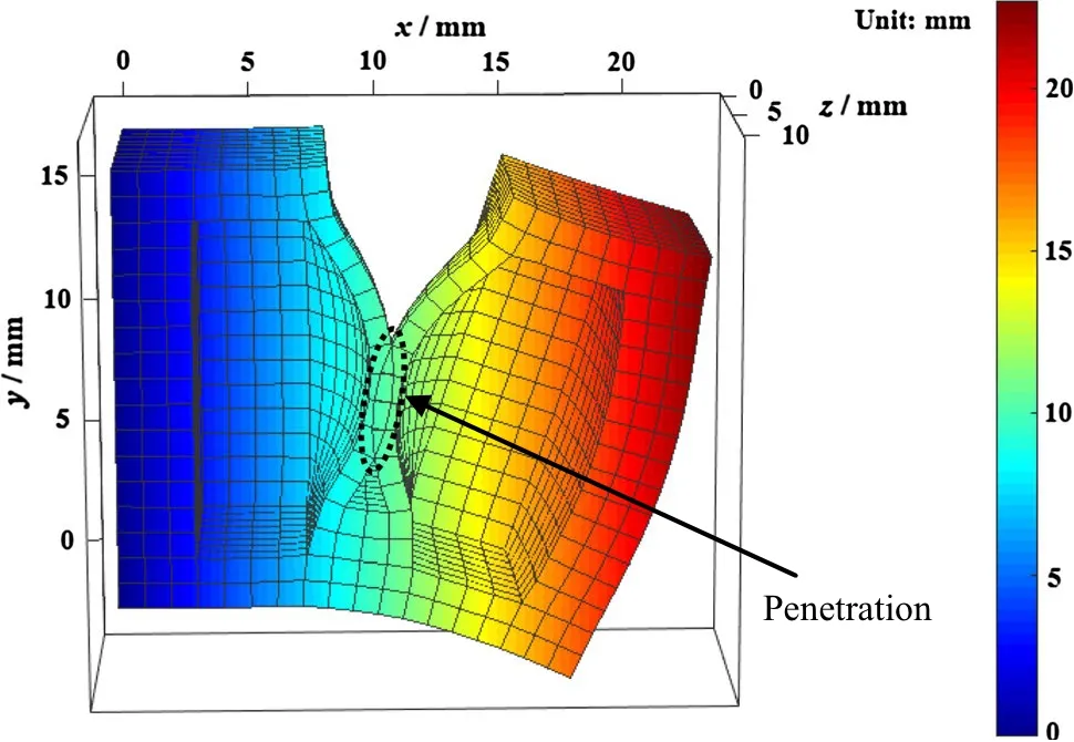
Fig. 4 Deformed configuration of half of two air chambers obtained using the model with single-point contact
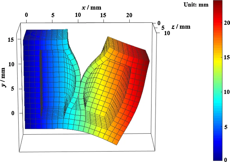
Fig. 5 Deformed configuration of half of two air chambers obtained using the model with multiple-point contact
In addition, the von Mises stress distribution of half of two adjacent air chambers is elaborated using the single- and multiple-point contact models. The mathematical expression of the von Mises stress is denoted as

where σx, σy, σzare the first, second, and third principal stress, respectively, and τxy, τyz, τzxare the shear stress.
Figures 6 and 7 show the von Mises stress distributions of half of two air chambers obtained using the models with single-point and multiple-point contact, respectively.
It can be seen from the color bar that the von Mises stress in the contact area between two adjacent air chambers and the root areas connecting two adjacent air chambers has already reached the maximum value, which aligns with the actual situation and should be particularly noted to facilitate the optimal design of a soft pneumatic actuator without destroying air chamber walls.
3.2 Contact analysis of multiple chambers
After analyzing the mechanical performance of the above two adjacent air chambers, in order to validate the proposed multiple-point contact model with respect to the clamped condition of one of the ends of multiple air chambers, a numerical example of static bending of the whole soft pneumatic actuator is implemented using MATLAB code, and the corresponding experimental research is then carried out.
Similarly, the internal deformation and whole configuration of half of the soft pneumatic actuator are investigated using the single- and multiple-point contact models, respectively, when air pressure is given by p = 35 kPa, as shown in Figs. 8 and 9.
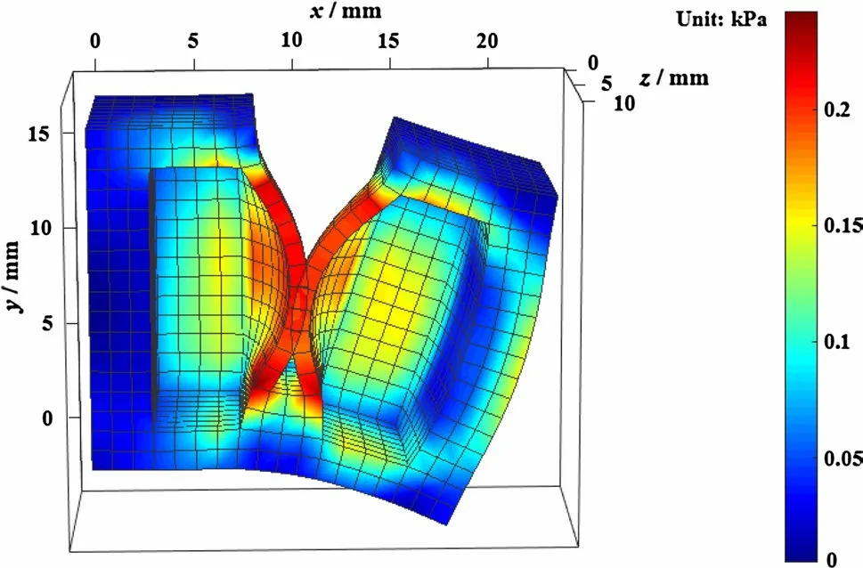
Fig. 6 von Mises stress distribution of half of two air chambers obtained using the model with single-point contact
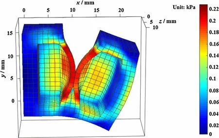
Fig. 7 von Mises stress distribution of half of two air chambers obtained using the model with multiple-point contact
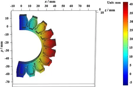
Fig. 9 Deformed configuration of half of the soft actuator obtained using the model with multiple-point contact
It can be clearly seen from Fig. 8 that two adjacent air chambers of the soft actuator have penetrated each other using the model with single-point contact. By contrast, the mutual penetration phenomenon does not appear with the multiple-point contact model, as shown in Fig. 9. The von Mises stress distribution of half of the soft actuator is also elaborated using the two models, as shown in Figs. 10 and 11. The color bar shows that the peak value of von Mises stress is in the contact area between two adjacent air chambers.
Finally, the deformed configuration and von Mises stress distribution of the whole soft actuator obtained with the proposed model with multiple-point contact is elucidated when air pressure is given by p = 35 kPa, as shown in Figs. 12 and 13. It is clearly shown that the large deformation of the whole soft pneumatic actuator can be effectively simulated using the proposed model, and the stress is concentrated primarily in the contact areas and the root areas connecting two adjacent air chambers, which is noteworthy for further optimizing the design of soft pneumatic actuators without damaging air chamber walls.
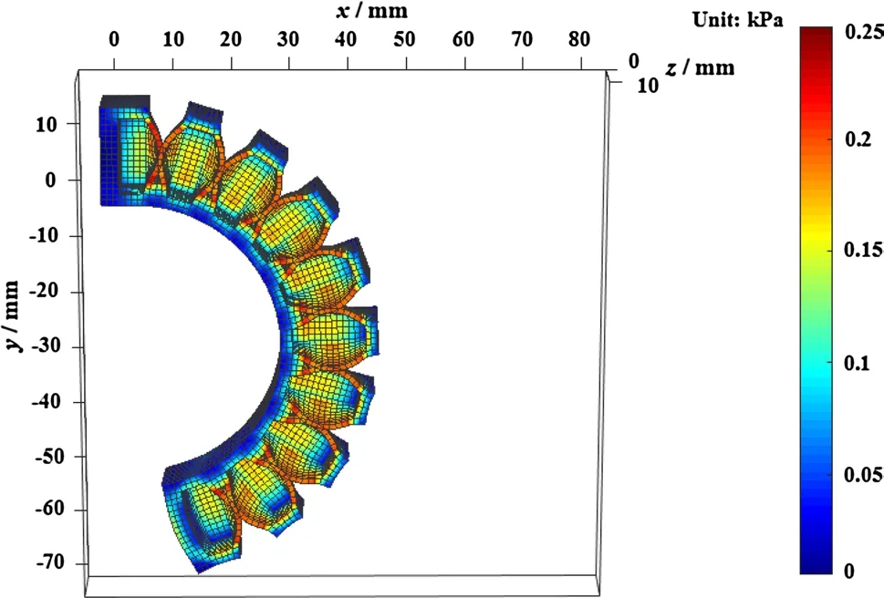
Fig. 10 von Mises stress distribution of half of the soft actuator obtained using the model with single-point contact

Fig. 11 von Mises stress distribution of half of the soft actuator obtained using the model with multiple-point contact
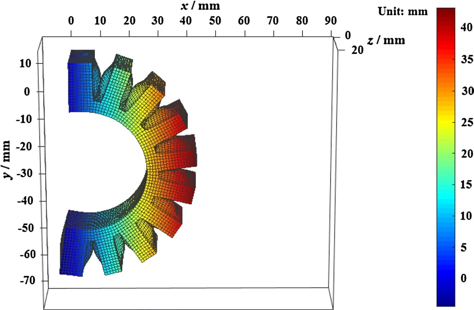
Fig. 12 Deformed configuration of the whole soft actuator obtained using the model with multiple-point contact
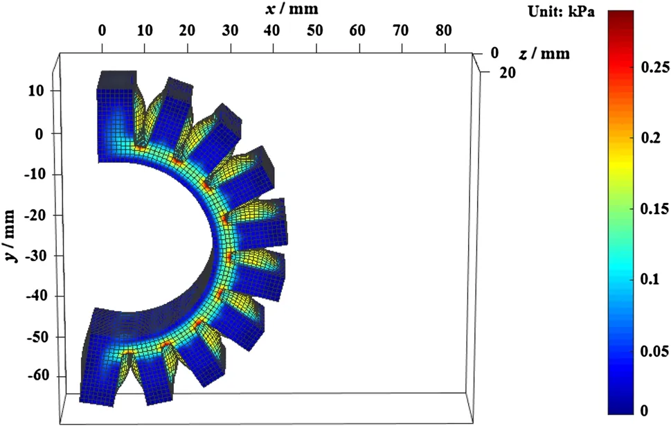
Fig. 13 von Mises stress distribution of the whole soft actuator obtained using the model with multiple-point contact
3.3 Experimental validation
In order to validate the proposed multiple-point contact model, a set of static experimental investigations are carried out on the whole soft pneumatic actuator when different values of air pressure p are taken.
Figure 14 shows the deformed state of the entire soft pneumatic actuator with the balck mark points at different air pressure values. The displacements of those points on the soft actuator are measured, and the corresponding deformed shapes of the soft pneumatic actuator can be easily depicted and compared using the models with single-point and multiple-point contact, respectively, as shown in Fig. 15.

Fig. 14 Deformed states of the entire soft actuator. a p = 5 kPa, b p = 15 kPa, c p = 25 kPa, d p = 35 kPa, e p = 50 kPa
Figure 15 shows measured and simulated deformed shapes of the pressurized soft actuator at different air pressure values. The air pressure p in Fig. 15 sequentially takes the values 5 kPa, 15 kPa, 25 kPa, 35 kPa, and 50 kPa. The black arrow indicates increasing air pressure values, and the solid lines, dashed lines, and dots correspond to the deformed shapes obtained using the multiple-point contact model, the single-point contact model, and the experimental data, respectively. It is found from Figs. 14a and 15 that at p = 5 kPa, the adjacent air chambers do not contact each other, and the results obtained with the use of multiple-point and single-point contact satisfactorily conform to the experimental data. Subsequently, as the air pressure is gradually increased, the deformation becomes progressively larger. It is further revealed that the simulation results obtained with the multiple-point contact model coincide with the experimental data, whereas those for the single-point contact model do not.
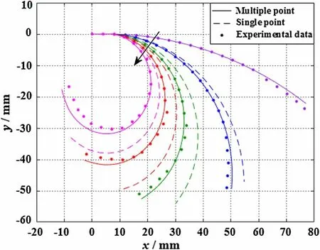
Fig. 15 Different deformed shapes of the entire soft actuator
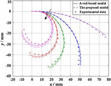
Fig. 16 Deformed shapes obtained using two types of models
3.4 Comparison with a rod-based model
A rod-based model for the soft actuator is presented in Ref. [14] that is based on Euler’s elastica theory. The bottom of the actuator is assumed to be an elastic rod, which is a simplified model without highlighting contact interaction between adjacent air chambers.
Figure 16 shows simulated deformed shapes of the pressurized soft actuator obtained using two types of models. The values of the air pressure p in Fig. 16 are the same as those in Fig. 15. The black arrow indicates increasing air pressure p, and the solid lines, dashed lines, and dots correspond to the deformed shapes obtained with the proposed multiple-point contact model, the rod-based model, and the experimental data, respectively. It is revealed that for values less than p = 15 kPa, the simulation results for the two types of models substantially agree with the experimental data within the range of small deformation, that is, the results obtained with the present model coincide with the results from the rod-based model. Then, starting from p = 25 kPa until p = 50 kPa, the simulation results of the proposed model are in line with the experimental data, whereas those obtained with the rod-based model gradually deviate from the experimental data, and the error in the simulation results relative to the experimental data increases. It is also proved that the precision in simulating the large bending deformation of the soft actuator is enhanced using the proposed model compared with the rod-based model.
4 Conclusions
In order to clearly display and inspect large deflection and contact phenomena of the soft pneumatic actuator considering contact interaction of soft materials rather than hard metal materials, modeling and analysis of the large deformable soft actuator is implemented in this paper by employing an effective enhanced model, using multiple-point contact to explain contact behaviors and avert penetration allowing for soft contact between two adjacent air chambers of the soft actuator. In contrast to the previous simple rod-based model without apparently emphasizing contact interaction which was used to analyze the whole deformation, the proposed model is able not only to explain deformed configurations and nonlinear large deformation, but also to clarify stress distribution law inside air chambers and the stress concentration phenomenon.
The feasibility and simulation precision of the present model with multiple-point contact are validated and compared through corresponding experimental study. It is demonstrated that the practical bending deformation of the soft actuator can be effectively simulated, while mutual penetration is smoothly circumvented, whereas this cannot be achieved by the model with single-point contact, that is, two adjacent air chambers have penetrated each other, and the two situations mentioned can be clearly observed from the deformed configuration variations and von Mises stress distribution. Furthermore, it is shown that as air pressure gradually increases, the eventual deformation becomes progressively larger, and the results obtained with the proposed model keep better pace with experimental data than those obtained by the rod-based model, and simulation accuracy is increased.
The stress concentration area is located at the contact area between two adjacent air chambers. Therefore, the air chamber walls should be modestly thickened to avoid damage in the structural design. In addition, the air pressure should be controlled within a certain range. In the future, this mechanical model can be extended to investigate the stress distribution of the grabbing or crawling soft robot.
AcknowledgementsThis research was supported by the National Natural Science Foundation of China (Grants 11772186 and 11272203).
杂志排行
Acta Mechanica Sinica的其它文章
- Geometric and material nonlinearities of sandwich beams under static loads
- Coupled thermoelastic theory and associated variational principles based on decomposition of internal energy
- Transient growth in turbulent particle-laden channel flow
- Experimental and theoretical investigation of the failure behavior of a reinforced concrete target under high-energy penetration
- Revealing the high-frequency attenuation mechanism of polyurea-matrix composites
- Efficient algorithm for 3D bimodulus structures
