Experimental and theoretical investigation of the failure behavior of a reinforced concrete target under high-energy penetration
2020-05-06FanlinMengTianbaoMaXiangzhaoXu
Fanlin Meng·Tianbao Ma·Xiangzhao Xu
Abstract The dynamic mechanical properties of concrete and reinforced concrete targets subjected to high-speed projectile impact loading have a significant influence on the impact resistance of protective structures. In this study, high-speed projectile penetration and perforation of concrete and reinforced concrete structures was carried out to determine the high-energy impact loading.The failure behaviors of projectile penetration and perforation of the concrete and reinforced concrete targets were investigated, and the destruction characteristics of the targets were measured. An analytical model was established using the principle of minimum potential energy. The results show that the theoretical predictions are consistent with the experimental data,indicating that the energy method is effective for predicting the dynamic mechanical properties of concrete and reinforced concrete targets under high-speed projectile penetration.
Keywords Reinforced concrete·Penetration·Analytical model·Failure behavior
1 Introduction
Concrete is the most widely used material in structural engineering.To overcome its low tensile strength,reinforcement bars or racks are implanted in the concrete to form a sturdy construction material, with excellent performance under compression and tension. Many special engineering structures utilize reinforced concrete, including bridges, dams,airport pavement,and nuclear power plants[1,2].Hence,the penetration and perforation of concrete targets has received considerable research attention. Damage to concrete structures when subjected to penetration load is extremely serious.Therefore,research on the dynamic mechanical properties of reinforced and plain concrete targets under high-energy penetration is important for evaluating the impact resistance of protective structures.
Numerous studies have investigated the failure behavior of concrete subjected to penetration load at an initial impact velocity of less than 1000 m/s,including engineering models(empirical formula), experimental measurement, theoretical modeling,and numerical analysis[2-10].Research and design have been carried out using an engineering model as the initial design method,an analytical model for theoretical support, numerical analysis for detailed design, and experimental measurement for verification. Theoretical methods can be employed to analyze the physical mechanism,based on certain reasonable assumptions,in order to simplify complex physical problems into simple mathematical form,and then to obtain approximate solutions to the mathematical problems.For example,Bernard[3]studied the resistance of a cone indenter that was slowly pressed into a metal medium,using the quasi-static cavity expansion theory, and formulated a solution for quasi-static expansion of cylindrical and spherical cavities in a semi-infinite medium.In another study,Goodier[11]considered the influence of strain hardening of a dielectric material on penetration based on the dynamic cavity expansion theory,as reported by Chadwick et al.[12],who applied spherical cavity expansion theory to a rigid ball-tometal target and obtained the dynamic cavity expansion for incompressible strain-hardened elastoplastic materials.Similarly,Hanagud et al.[5]applied spherical cavity expansion theory to investigate the problem of high-speed penetration of strain-hardened dielectric materials,and then obtained an analytical solution of dynamic cavity expansion of dielectric compressibility by introducing a locking density related to the Hugoniot curve.In recent years,the range of application of the cavity expansion theory has been extended.For example,Satapathy and Bless[6,13]applied the theory to study the anti-penetration behavior of ceramic materials,while Oucif and Mauludin[7]used it to predict the size of hypervelocity penetrating pits.Additionally,Xu et al.[8]combined the cavity expansion theory and the crack-elastic model to study the penetration of concrete materials in the Lagrange coordinate system,and Warren[9]analyzed the influence of the strain rate on the cylindrical cavity expansion theory and proposed a corresponding solution.
In an early work,Young[14]proposed a formula,known as Young’s equation, for estimating projectile penetration based on a large amount of experimental data,and expressed the penetration depth as a function of the projectile geometry,initial velocity,projectile mass,and the target material.Subsequently,Bernard[3]compiled multiple sets of experimental data and presented empirical formulas for rock/concrete penetration. These formulas are a function of the density and uniaxial compressive strength of the material. In addition,Sliter[15]proposed a dimensionless collapse thickness formula, while Berriaud [16] proposed a concrete target penetration limit thickness formula based on experimental data obtained from the French Atomic Energy Commission(CEA)and the National Electric Company(EDF).In a study by Chelapati et al. [17], the authors developed a model to estimate the penetration limit thickness and the collapse limit thickness of a concrete target based on the Ballistic Research Laboratory(BRL)penetration depth formula.More recently,Li et al. [18] proposed the penetration depth, penetration thickness, and collapse thickness for a flat rigid head projectile perforation of a reinforced concrete target,while Liu et al. [19] and Chen et al. [20] proposed a formula for the thickness of the plug and the ballistic limit of the projectile perforation of a reinforced concrete target based on the cavity expansion theory and dimensional analysis.
When a projectile perforates a concrete target, the target may produce numerous crushed blocks on the rear face,which may cause serious secondary damage to personnel and equipment.Therefore,evaluating the range of impact loading on a concrete target is important.The present study investigated the high-speed projectile penetration and perforation of concrete and reinforced concrete structures to determine the high-energy impact loading.The failure behavior of the structures was investigated, and the damage characteristics were evaluated. An analytical model was established using the energy method. The energy dissipated during the projectile penetration of the concrete was analyzed in three stages, namely initial cratering, tunneling, and shear plugging. Dynamic cavity expansion theory was used to derive the force of the projectile nose during the cratering and tunneling stages,and the corresponding energy dissipation was obtained according to the displacement integral of each stage.The shear failure stress was obtained using the von Mises failure criterion;the energy dissipation in the shearing stage was then calculated using the failure strain of the concrete under impact loading. Analytical expressions for the depth of penetration,diameter of the damage to the rear face,and the ballistic limit were obtained based on the principle of minimum potential energy.The theoretical predictions were consistent with experimental data,indicating that the energy method is effective for predicting the dynamic mechanical properties of concrete and reinforced concrete targets subjected to high-speed projectile impact.Finally,the effects of target thickness and projectile diameter were analyzed.
2 Experiment
2.1 Material parameters
The concrete used in this experiment consisted of ordinary cement with minimum strength of 42.5 MPa, 10% fly ash content,and 3.6%antifreeze.The fine aggregate was made of natural river sand, with average fineness of 2.8, and the coarse aggregate consisted of crushed limestone with maximum particle diameter of 40 mm.The reinforcing bars were#45 steel with a diameter of 10 mm and tensile strength of 500 MPa.The concrete targets were poured with the same batch of concrete and were conserved for 35 days using the standard natural curing method. Three standard concrete specimens were poured for each concrete target, and the maintenance conditions were also consistent. The average compressive strength of the concrete was 50.0 MPa. Test results for selected representative specimens are shown in Fig.1.
The projectile material was 921A steel with yield strength of 835 MPa. The diameter, length, and weight of the steel projectile measured 100 mm, 192 mm, and 9.7 kg, respectively.The concrete target was in the shape of a cuboid.The transverse and longitudinal lengths of the target were 2.0 m,and the thicknesses were 1.25 m, 1.5 m, 1.75 m, and 2.0 m. Each steel layer was spaced at 25.0 cm, with 10 reinforcing bars at a distance of 20.0 cm in both the horizontal and vertical directions, and the cross joints of each layer were connected by longitudinal lacing. The reinforcing bar frame was centered in the target body, and the minimum dimensions of the mesh formed by the reinforcing bars were 20.0 cm ×20.0 cm ×25.0 cm,as shown in Fig.2.
2.2 Experimental setup
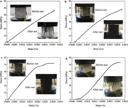
Fig.1 Test results for specimens
Figure 3 shows the experimental setup of the projectile penetrating the concrete target. The projectile was accelerated using a 100 mm diameter smooth bore cannon. The muzzle was on the same horizontal line as the center of the target,and the distance between them was 15.0 m.High-speed cameras were arranged in front of and behind the target, 6.0 m from its center axis.The high-speed photographic lens was on the same horizontal line as the center of the target.Two high-speed cameras in front of the target were used to record the flight process of the projectile,the target attitude,and the destruction process of the concrete/reinforced concrete front target,while two high-speed cameras behind the target were used to record the target attitude and damage to the concrete.On the other side of the target, a white wooden board was used as the background,and a black pole was created every 1 m on the background board such that the speed of the projectile was determined by the time it took the projectile to travel between the two benchmarks.
2.3 Experimental results
2.3.1 Experimental results of projectile perforation of concrete/reinforced concrete target
Eight experimental tests were conducted on projectile perforation of the concrete target. Each target had an obvious open pit area, tunnel area and shear plugging area. All the projectiles perforated the target except for the#1 target.The upper parts of the#2 and#3 targets were completely crushed.Cracks occurred throughout the targets,and the reinforcing bars were generally bare, bent, and pulled out. The projectiles of #5, #6, and #8 hit or broke the reinforcing bars at different degrees.The heads of the projectiles were abraded,but they were uneven and were obviously biased to one side.Figure 4 shows the perforation process of the projectile into the concrete target.
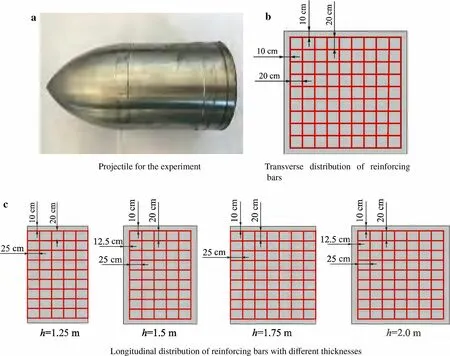
Fig.2 Projectile and reinforcement layout for the experiment
Figures 5 and 6 show the final damage to the concrete/reinforced concrete targets. Compression waves are continuously produced during projectile penetration of concrete targets, and the strength of the compression wave is larger than the dynamic damage of the concrete strength.Stress concentration will occur at some locations due to the anisotropy and nonuniformity of reinforced concrete, leading to the formation of cracks. These cracks will gradually expand outward with the penetration process to form radial penetration cracks.Additionally,in the projectile perforation process, the plug always disintegrates into concrete fragments owing to the low tensile strength of the concrete (as concrete is a brittle material)and the tensile stresses arising from complex reflections of the stress wave prior to shear plugging. Therefore, many cracks occurred in the concrete target,along with damage to the structural integrity.The projectile penetrated the concrete targets vertically and caused serious damage. In the experiments, targets #5 to #8 were reinforced concrete targets, similar to concrete targets, and the destruction of these targets was characterized by cratering, tunneling, and shear plugging. However, the depth of the cratering stage,the length of the tunneling stage,and the thickness of the shear plugging differed from those of the concrete target.The shear plugging area was funnel-shaped,but the bottom of the shear plug was a complete concrete layer supported by the reinforcing bars. The target velocity of projectiles #5 to #8 varied from 1283 to 1481 m/s,whereas the depth of the pit,the length of the tunnel,and the thickness of the shear plug remained essentially the same,which is consistent with the configuration of the reinforcing bars.The crater area was cut off from the second layer of the reinforcing bars,with a tunnel connecting the space between the second and third layers of the reinforcing bars. Shear plugging occurred in the third to fourth layers as well as the surface of the target body. This indicates that the reinforcing bars in the target had a reinforcing effect on the concrete,compared with cratering,tunneling,and shear plugging in the concrete target,which enhanced the penetration resistance of the concrete.Moreover,the number of layers of reinforcing bars in the thickness direction had an important influence on the failure behavior of the reinforced concrete.
Parameters including the initial impact velocity and the depth of each stage were measured using the high-speed cameras,as summarized in Table 1.
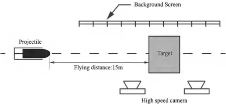
Fig.3 Experimental layout
2.3.2 Projectile penetration of the reinforced concrete target
Nine experimental penetration tests were conducted on reinforced concrete.Each target had obvious areas of a cratering stage; however, the tunnel and shear plugging areas were not obvious. Several concrete blocks collapsed on the rear face of the#1 and#2 targets.However,the reinforcing bars prevented them from falling,and were deformed by the bearing force.The caving appearance of the rear face of targets#3 to #9 was not obvious. The number of cracks and the degree of protrusion decreased with increasing thickness of the reinforced concrete target. When the projectile hit the reinforcing bars,the area of the cratering stage increased and the cracks obviously increased.Figure 7 shows the damage process of the projectile penetrating the reinforced concrete target,and Fig.8 shows the damage to the front and rear faces of the three thickness targets.Parameters including the initial impact velocity,the depth of each stage,and the number of bars hit were measured using high-speed cameras, and the results are summarized in Table 2.
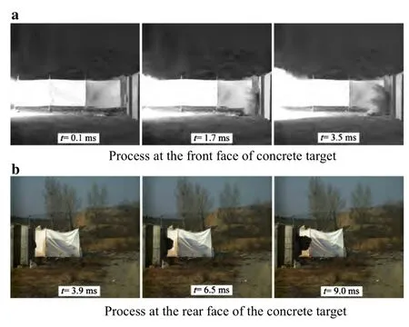
Fig.4 Destruction process of projectile penetrating#7 concrete target
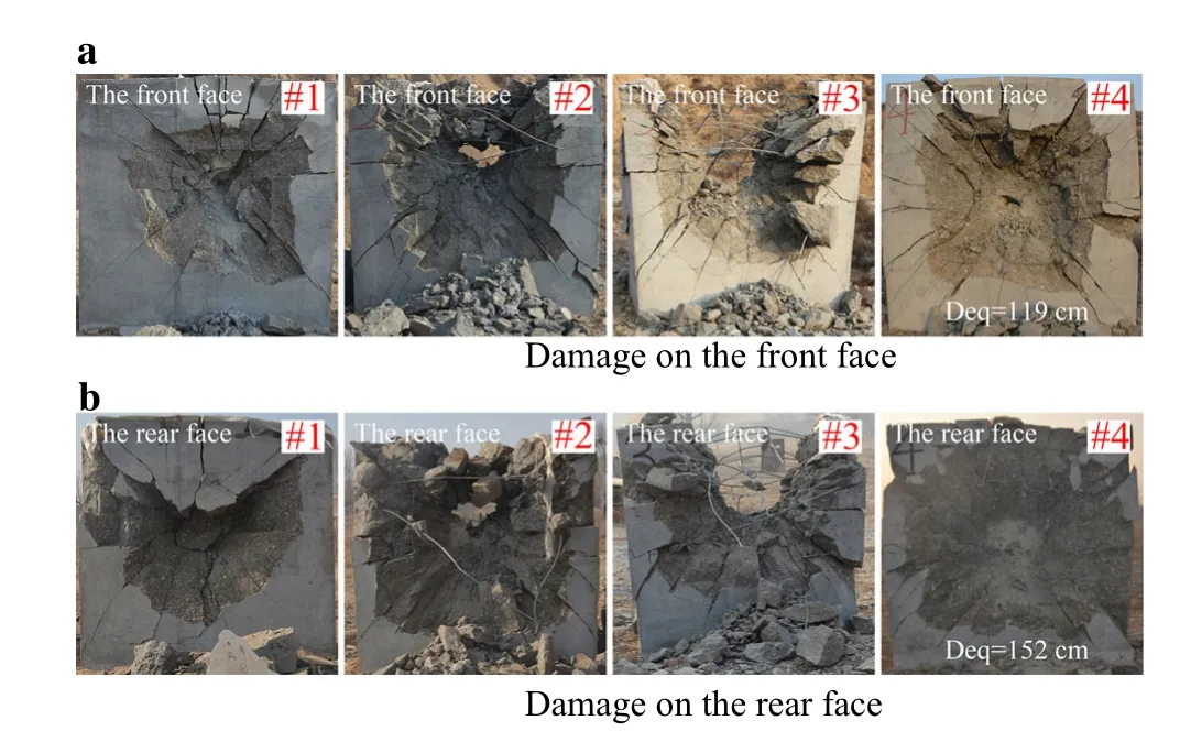
Fig.5 Destruction of#1-#4 concrete targets
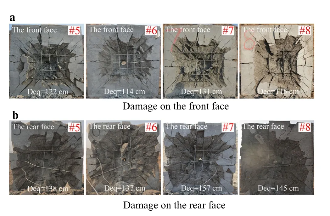
Fig.6 Destruction of#5-#8 reinforced concrete targets
The area of cratering of the reinforced concrete target close to the target surface is smaller than the target of the reinforcing bars 12.5 cm from the target surface,indicating that the reinforcing bars had an obvious tensile effect,and the surface close to the target can effectively reduce the collapse of the target under impact loading.Table 3 presents the near-surface layout of the reinforcing bars.A comparison of data shows that the penetration depth of the projectile in direct contact with the reinforcing bars is smaller at similar initial impact velocity. The reinforcing bars have an obvious restraining effect on concrete damage and can effectively prevent concrete collapse due to damage on the rear face of the reinforced concrete target.
3 Analytical model
3.1 Dynamic cavity expansion theory
The damage to the concrete target due to the impact of the rigid projectile includes the depth of cratering kd and the diameter of the penetrating hole,which is related to the diam-eter of the projectile dP.In works by Forrestal et al.[23]and Forrestal et al.[21],the authors set k =(0.707+lp/dp)to be 2.0.In another study,Chen et al.[20]defined lpas the length of the head of the projectile based on slip line theory;according to this work,the axial stresses of the projectile during the cratering process and the penetration process are given as:

Table 1 Experimental data for projectile perforation of concrete and reinforced concrete targets

Fig.7 Destruction process of#8 reinforced concrete target
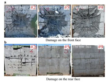
Fig.8 Destruction of#2,#5,and#9 reinforced concrete targets

where x and V are the instantaneous depth of penetration and the velocity,respectively,ρ is the density of the concrete target,c is a constant,and fcis the compressive strength of the concrete.S is an empirical constant which is determined using fc,and can be formulated as follows[21-23]:

In Eq.(2), N*is the shape factor of the head of the projectile. Previous studies [18,22] formulated the functional relationship between N*and the shape factor of the projectile nose,and the influence of the shape of the projectile nose on the penetration process was clarified.The shape factor N*of a circular head can be simply expressed as:

where ψ is the caliber radius head(CRH)value.
The velocity of the projectile V1at the end of the cratering stage (or at the beginning of the penetration stage) and the constant can be solved as follows(refer to Refs.[21,23]):

3.2 Energy dissipation mechanisms
According to the projectile penetration process, the energy dissipation can be analyzed in stages, and the mechanisms can be described as follows.(1)The main energy dissipation in the first stage is the work done by the projectile during the catering stage.(2)The main energy dissipation in the second stage is the work done by the projectile during the tunneling stage.(3)The main energy dissipation in the third stage is the work done to achieve shear plugging formation and tensile deformation of the reinforcing bars. Ignoring the effects of small energy dissipation such as friction during penetration,the overall energy dissipation of the penetration process can be expressed as:

where W1is the energy dissipation in the first stage, and W2is the energy dissipation in the second stage. When the thickness of the target is less than a certain value,there will be no second stage during the penetration process;thus,the energy dissipation in the second stage W2= 0. W3is the energy dissipation in the third stage, and W4is the kinetic energy of the plug.When the projectile cannot complete the penetration and cannot reach the third stage,there will be no shear plugging stage or plug; thus, W3= 0 and W4= 0.The velocity of the plug is equal to 0 when the ballistic limit is reached; thus,the kinetic energy of the plug W4= 0 for the ballistic limit scenario.The kinetic energy of the plug is defined as:

where Vsis the velocity of the plug and msis the mass of the plug,which can be obtained as:

The axial resistance of the projectile during the cratering stage is the energy dissipation in the first stage:

Table 2 Experimental data for projectile penetration of reinforced concrete targets

Table 3 Experimental data for the collapse size of the reinforced concrete targets

The energy dissipation in the second stage is the work done by the axial resistance of the projectile during the penetration and tunneling process:

When the shear stress reaches the critical value,the plug will immediately separate from the concrete target,because concrete is a brittle material.Moreover,when a stress wave propagates to the rear face of the concrete,it reflects and generates tensile stress waves that cause plug breakage,because the tensile strength of the concrete is low (approximately one tenth of the compressive strength).According to the von Mises failure criterion, the shear stress of the concrete iswhen shear failure occurs.Reinforcing bars in concrete generally have a net-like distribution and resist projectile penetration throughout perforation.For the rear plug,the reinforcing bars are stretched, and even fracture, when failure occurs. Thus, separation of the rear plug from the reinforced concrete slabs also includes tensile failure of the reinforcing bars. The resistant force ahead of the projectile nose is given as:

where Asis the surface area of the plug, and the value of δ is related to the target material;δ is mainly related to the ratio fc/ftand increases with the ratio.For concrete targets,δ is generally around 60◦[24,25]. For reinforced concrete targets,the thickness of the plug decreases with the increase in the reinforcement ratio and concrete strength,which leads to a small increase in δ,and fbaris the tensile failure force of the reinforcing bars.According to Ref.[26], fbaris given as:


Fig.9 Schematic of concrete back target plug failure
Figure 9 shows a schematic of the failure process of the shear plug of the concrete target.The work done by the shear stress τfin the shear failure of the concrete is the energy dissipation of the shearing process.
In this study,the linear density shear force along the shear direction was defined as τ0=τf·h*/cos δ[27].After downward displacement of the plug,the linear density shear force along the shear direction is

The energy dissipation during the shearing process is

The failure strain of the reinforced concrete is given as[28]

where Kcis the constraint constant of reinforced concrete,which is related to the diameter of the reinforcing bars and the method of reinforcement.For reinforced concrete, Kc>1,and in this study, Kc= 1.1 for reinforced concrete with a reinforcement ratio greater than 0.5%. εcuis the ultimate strain of the reinforced concrete,εccis the peak strain of the reinforced concrete,and εc0is the peak strain of the concrete,which is given as[28]

Assuming that the ultimate displacement lmaxof the shear plug moving away from the surrounding concrete is approximately the deformation of the concrete plug subjected to the impact loading of the projectile.Then,lmaxcan be expressed as

Inserting Eqs.(13),(16),and(18)into Eq.(15)and integrating, the expression for the energy dissipation of shear plug formation can be obtained as:

Assuming that during the squeezing process the reinforcing bars move along with the concrete plugs, and they do not interact,then the tensile failure energy dissipation of the reinforcing bars is

where rpcan be reduced to the intermediate section radius of the shear plug.

Equation (16) gives the failure strain of the reinforced concrete under impact loading. Combining Eqs. (16) and(20), the tensile failure energy of the reinforcing bars can be obtained as follows:

The total energy dissipation W of the entire penetration process can be obtained by inserting Eqs.(8),(10),(11),(19),and(22)into Eq.(7):
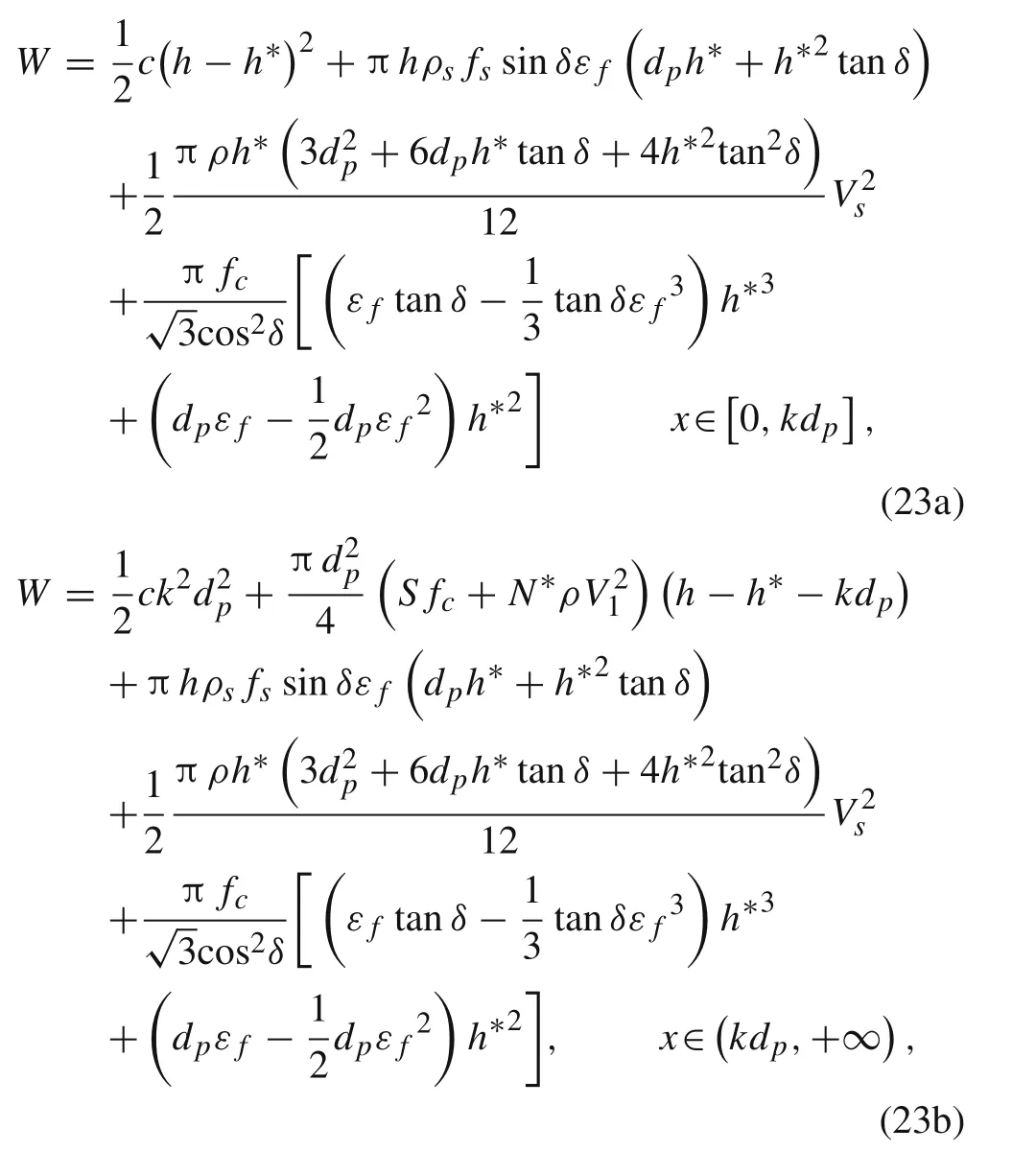
where x = h-h*for x∈[0,kdP] and x = kdpfor x∈(kdP,+∞).
According to the principle of minimum potential energy,the thickness h*of the plug can be obtained by minimizing the total energy dissipation of the penetration process.

The penetration kinetic energy of the projectile is equal to the total energy dissipation for the ballistic limit scenario,and the ballistic performance of the projectile penetrating the reinforced concrete can be obtained. Substituting Eq. (23)into Eqs. (25) and (26), the relationship between the thickness h*BLof the shear plug and the ballistic limit VBLcan be obtained.The ballistic limit VBLcan be calculated as follows:
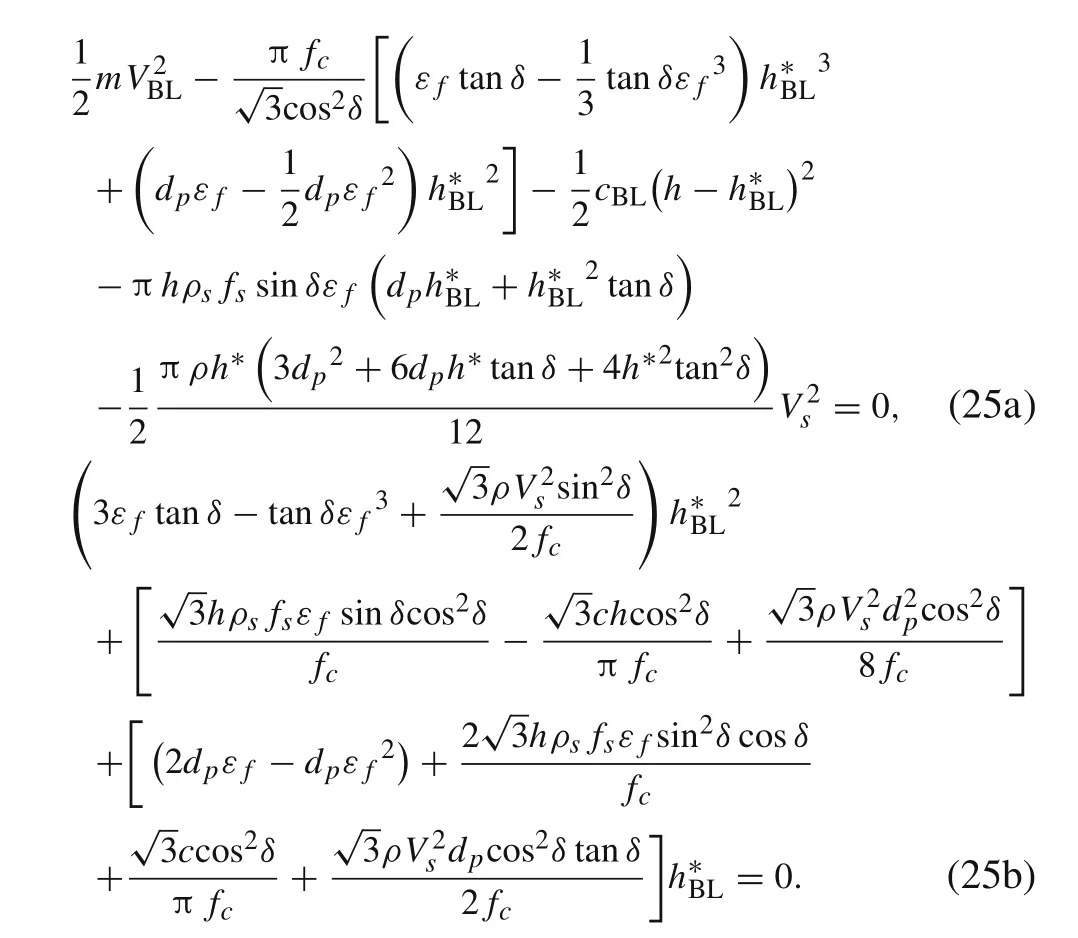
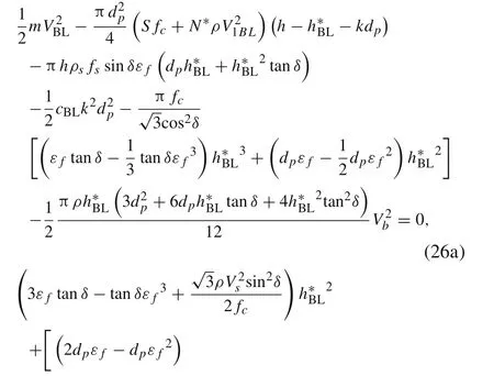
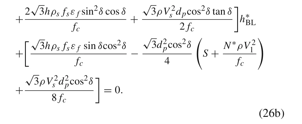
The thickness of the shear plug can be obtained from Eq. (25); then, the total energy dissipation in the penetration process can be determined.The residual velocity of the reinforced concrete target with finite thickness of the projectile can be evaluated by applying the conservation of energy as follows:

4 Comparison of predicted results and experimental data
The accuracy of the analytical model can be verified by comparing the results with experimental data. The verification parameters include the thickness of the shear plug,the ballistic limit,and the penetration depth.
4.1 Projectile perforation of concrete/reinforced concrete target
The analytical results were compared with experimental data presented in Sect. 2.3.1. It is assumed that the projectile is rigid and the material parameters of the projectile are m = 9.7 kg, dp= 0.1 m, CRH = 1.2, lp= 0.1 m, the empirical constant k = 1.707 and the head shape function N*= 0.249.The relevant parameters of the concrete target are ρ =2440 kg/m3,h =1.0 m,and the failure strain given by Eq.(16).The#1 to#4 target plates are concrete targets,and#5 to#8 are reinforced concrete targets with a reinforcement ratio ρs=0.2%;however,Kc=1.0 in Eq.(16)owing to the low reinforcement ratio. We set tan δ = 2.90 in the calculation based on experimental data.
According to experimental data, the plug formed is distributed to within 5.0 m behind the target.Taking the center of the target as the origin,it is considered that the concrete plug is formed into a plug and then throws a flat throwing motion.The velocity of the concrete plug is estimated to be approximately 6.0 m/s.Table 4 presents a comparison of the theoretical calculation results for the plug thickness considering the kinetic energy of the plug at the different residual velocities of the shear plug. When the velocity of the plug reaches 20 m/s,the length of the concrete fragments behind the target is nearly 18 m,which is far from the experimentalvalue.A comparison of the theoretical calculation results for the plug thickness at different plug velocities indicates that the kinetic energy of the plug has a weak influence on the thickness of the plug.The maximum difference between the different plug speeds is within 7.0%; thus, the effect of the kinetic energy of the plug is negligible.

Table 4 Comparison of theoretical calculation results for plug thickness considering plug kinetic energy
Analysis of the kinetic energy of the plug(Table 4)indicates that it can be ignored for a scenario in which the residual velocity of the projectile is significantly higher than the velocity of the plug.The calculation of the high residual velocity can be simplified to facilitate the calculation.The total energy dissipation of the projectile perforation of the reinforced concrete target can be simplified as follows:
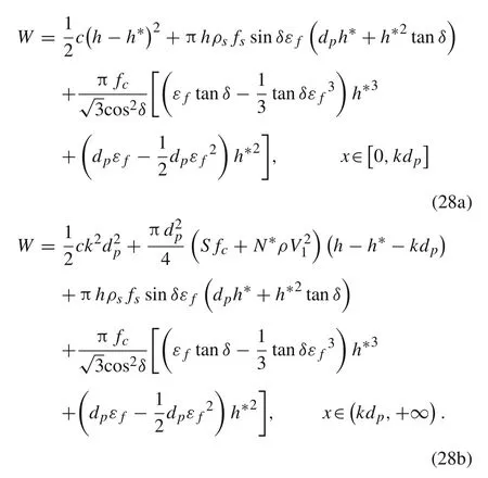
According to the principle of minimum potential energy,the thickness h*of the plug can be obtained by Eq.(24).
The ballistic limit VBLis simplified as:
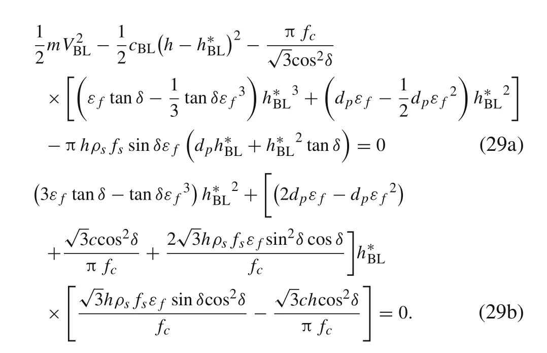
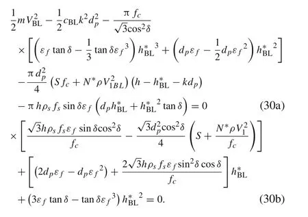
Table 5 presents a comparison of the calculation results and experimental data.The theoretical calculation results for the plug thickness are consistent with those of the experimental data, and the errors are within 13.0%. The main reasons are as follows. (1) We assumed that all the reinforcing bars are active in the shear plugging formation and that they move together with the shear plug during the shear plugging process,which results in some differences between the prediction of the tensile failure energy of the reinforcingbars and the actual situation.(2)There are many factors influencing the experimental process, such as coarse aggregate,steel bar, and penetration angle, which lead to calculation errors.When the initial impact velocity is 950 m/s,the projectile does not perforate the concrete target; the ballistic limit obtained from the analytical model is 967.7 m/s,which is higher than the non-perforation velocity of 950 m/s for the concrete target. The thickness of the plug at the ballistic limit is 379.9 mm, which is also in agreement with the experimental data.

Table 5 Comparison of theoretical calculation and experimental data

Table 6 Comparison of theoretical calculation results and experimental data for penetration into reinforced concrete
4.2 Projectile penetration of reinforced concrete target
The theoretical calculation results were compared with the experimental data presented in Sect. 2.3.2. The parameters of the reinforced concrete target and those of the projectile are consistent with the results presented in Sect. 4.1.Table 6 provides a comparison of the calculated results and experimental data.The analytical model predicted a ballistic limit of 2084 m/s at a target thickness of 1.25 m, which is much higher than the initial impact velocity; thus, the theoretical calculation of perforation did not include the shear formation energy W3or the kinetic energy of the plug W4.The results obtained from the model were generally smaller than the experimental data, as the theoretical calculations of W1and W2did not include the tensile failure energy of the reinforcing bars. Under the experimental conditions,the material and geometry of the projectile and the target remained the same, and the thickness of the target did not affect the results. The only variable was the initial impact velocity.However,the initial impact velocity varied slightly in the experiment, such that the results obtained from the model fluctuate slightly.The errors are not higher than 22.0%except those for#2 and#4.The main reason is that there are many factors influencing the experimental process, including coarse aggregate, steel bar, and penetration angle. In experiment #1, the projectile initial penetration velocity is almost the same as that in experiment#2,but the penetration depth is quite different.Another reason could be the insufficient filling and low strength of the target.It is also possible that after penetration has been completed,unstable concrete is excessively detached, resulting in a large measurement result.
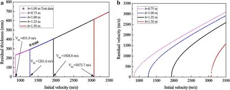
Fig.10 Effect of the target thickness on the a residual thickness and b residual velocity
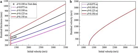
Fig.11 Effect of the projectile diameter on the a residual thickness and b residual velocity
5 Parameter analysis
5.1 Target thickness
Figure 10 shows the effect of the target thickness on the residual thickness and residual velocity, respectively. Figure 10a shows that the ballistic limit increases sharply as the thickness of the reinforced concrete target increases; however, the residual thickness for different measures of target thickness is consistent with the projectile perforation of the reinforced concrete target scenario. The residual thickness is related to the material parameters of the reinforced concrete target and the size parameters of the projectile, and is independent of the target thickness.The ballistic limit of reinforced concrete with h = 1.25 m reached 1928.8 m/s.This also verifies the results for the projectile presented in Sect.2.3.2,which are not higher than 1928.8 m/s,and thus it cannot perforate the reinforced concrete target.Figure 10b shows that the residual velocity of the projectile decreases sharply with increasing thickness of the reinforced concrete target. This is because increasing the thickness of the reinforced concrete target leads to a sharp increase in the energy dissipation during the penetration process.For a given thickness,when the initial impact velocity is slightly larger than the ballistic limit,the residual velocity increases sharply with the increase in the initial impact velocity,whereas when the initial impact velocity is much larger than the ballistic limit,the residual velocity increases approximately linearly with the increase in the initial impact velocity.
5.2 Projectile diameter
Based on the test results for projectile perforation of a reinforced concrete target presented in Sect.2.3.1,the shape and proportion of the projectile remain unchanged, the projectile diameter is changed, and the size of the projectile is increased proportionally, which leads to an increase in the projectile mass.The masses of the projectiles with diameters of 0.075 m,0.100 m,0.125 m,and 0.150 m are 4.1 kg,9.7 kg,18.9 kg,and 32.7 kg,respectively.Figure 11 shows the effects of the projectile diameter on the residual thickness and residual velocity.Figure11 as hows that the residual thickness increases with increasing projectile diameter.This is because the residual thickness is directly related to the diameter of the projectile penetration. The kinetic energy of the projectile increases with increased projectile diameter,causing serious damage to the reinforced concrete target.Figure 11b shows that the ballistic limit and residual velocity do not change with the increase in projectile diameter,because the ballistic limit is fixed for a given target,which is consistent with the conclusions in previous works[20,22,26].
6 Conclusion
Reinforced concrete structures are widely used to protect large, vital, or strategically important components against high-energy dynamic loads.Failure of a reinforced concrete structure under high-energy dynamic loads poses a significant risk.Therefore,accurate assessment of the failure range of large-scale reinforced concrete structures subjected to high-energy dynamic loads is of great importance.
In this study,high-energy dynamic loads were determined using a large-caliber projectile with high initial impact velocity. Different parameters and damage on the target were measured after the experiment and used as a benchmark.Theoretical calculation results obtained from the model were compared with the actual experimental data.The following conclusions can be drawn from the findings of this study.
(1) Direct contact of the projectile with the reinforcing bars may reduce the depth of damage. The reinforcing bars obviously restrain concrete damage effects and effectively prevent the concrete from falling.
(2) The energy method can be effectively used to establish the process for analyzing the penetration of rigid projectiles into reinforced concrete.
(3) The theoretical results of reinforced concrete damage after penetration are consistent with experimental data,indicating that the theoretical model can accurately predict the characteristics of reinforced concrete materials subjected to impacts.
(4) The residual thickness increases with increasing thickness of the reinforced concrete target and projectile diameter. However, the residual velocity and ballistic limit increase sharply and are consistent with the increase in the thickness of the reinforced concrete target and projectile diameter,respectively.
AcknowledgementsThis project is supported by the National Natural Science Foundation of China(Grant 11822203)and the China Postdoctoral Science Foundation(Grant 2018M641209).
杂志排行
Acta Mechanica Sinica的其它文章
- Geometric and material nonlinearities of sandwich beams under static loads
- Coupled thermoelastic theory and associated variational principles based on decomposition of internal energy
- Transient growth in turbulent particle-laden channel flow
- Revealing the high-frequency attenuation mechanism of polyurea-matrix composites
- Efficient algorithm for 3D bimodulus structures
- Generalized stiffness and effective mass coefficients for power-law Euler-Bernoulli beams
