Efficient algorithm for 3D bimodulus structures
2020-05-06QinxuePanJianlongZhengPihuaWen
Qinxue Pan · Jianlong Zheng · Pihua Wen
Abstract The bimodulus material is a classical model to describe the elastic behavior of materials with tension-compression asymmetry. Due to the inherently nonlinear properties of bimodular materials, traditional iteration methods suffer from low convergence efficiency and poor adaptability for large-scale structures in engineering. In this paper, a novel 3D algorithm is established by complementing the three shear moduli of the constitutive equation in principal stress coordinates. In contrast to the existing 3D shear modulus constructed based on experience, in this paper the shear modulus is derived theoretically through a limit process. Then, a theoretically self-consistent complemented algorithm is established and implemented in ABAQUS via UMAT; its good stability and convergence efficiency are verified by using benchmark examples. Numerical analysis shows that the calculation error for bimodulus structures using the traditional linear elastic theory is large, which is not in line with reality.
Keywords Elastic theory · Bimodulus material · 3D complemented algorithm · Finite element method · Generalized elastic law · General 3D shear modulus
1 Introduction
A large number of experimental studies [1, 2] have shown that the tensile modulus and compressive modulus are different, e.g., in polymethyl methacrylate [3], polyester acrylic plastics, concrete, etc. [4]; For example, the composite material glass fiber AC-30 (20 °C) has tensile and compressive modulus of 1390 MPa and 200 MPa, respectively; i.e., the ratio E+/E-reaches 7 [5]. Some special phenomena, such as membrane folding and cell sensing, can also be perfectly explained or predicted based on bimodulus theory [6]. Therefore, it is necessary to study the bimodulus problem in science and engineering.
In 1941, Timoshenko [7] proposed the concept of bimodulus materials. In 1982, Ambartsumyan and Khachatryan [8, 9] published the first monograph on bimodulus problems and a constitutive theory based on the difference between the tensile and compressive moduli. Since then, investigation of this topic has attracted interest from many researchers in the world; For example, the constitutive relation has been improved from different perspectives [10-13], and analytical solutions for the bimodulus problem have been obtained in simple cases [4, 14, 15]. Recently, an important development in bimodulus theory was the extension of the traditional variational principle for smooth constitutive relations to systems with nonsmooth constitutive relations, providing insight into the character of the solution of bimodulus elastic problems, which is helpful for constructing efficient numerical solution algorithms [16].
In general, analytical solutions of 3D bimodulus elasticity problems are difficult to obtain, especially when the geometry and loading conditions are not regular. Therefore, numerical methods are necessary for the analysis of structures. However, due to the jump of the Young’s modulus in the constitutive equation, most algorithms show low convergence efficiency and poor adaptability [17-20]. The parametric variational principle (PVP) algorithm [21] turns a bimodulus problem into a complementary problem based on a variational principle applied to the parameters to avoid the iterative update of the stiffness matrix, resulting in considerable convergence efficiency. However, for large-scale structures, the convergence efficiency of the PVP algorithm is restricted due to the dimensionality of the parameter variables. To overcome this difficulty, the authors have used a continuous model and meshless method to demonstrate the degree of accuracy and convergence of the proposed technique in comparison with analytical solutions [22].
Recently, Du [3] proved that the potential energy functional of a bimodulus problem is a strictly convex function whose solutions exhibit uniqueness and semilinearity. They found that the reason for the poor convergence of traditional iterative algorithms is the adoption of a secant stiffness matrix. Thus, an alternative tangential stiffness algorithm, either 2D or 3D, and a 2D complemented stiffness algorithm were established and implemented in ABAQUS using the UMAT subroutine. The numerical results show that those algorithms exhibit secondorder convergence like the Newton-Raphson algorithm, which is of great significance to promote the application of bimodulus theory in engineering. Recently, topology optimization design for bimodulus materials was investigated using these algorithms [5]. However, the realization of the tangent algorithm is more complex for 3D problems for bimodulus materials compared with the complemented algorithm. Unfortunately, they only deduced the shear modulus of a bimodulus material in the 2D case rather than the 3D shear modulus in the general case. Therefore, it is of theoretical significance to study the shear modulus in the 3D case. Due to the degree of difficulty, existing bimodulus research has mainly focused on simple structures and boundary conditions. It is thus necessary to develop a strongly adaptable, highly efficient, and easy-to-implement 3D numerical algorithm for use in engineering.
In this paper, a new 3D complemented algorithm is established for the first time by complementing the three shear moduli of the constitutive equation in principal stress coordinates, and the 3D shear modulus is derived theoretically based on a limit principle. Therefore, the resulting complemented algorithm is theoretically self-consistent, which is convenient for use in engineering applications. The remainder of this manuscript is organized as follows. In Sect. 2, the constitutive equation in Cartesian coordinates is presented. In Sect. 3, a self-consistent shear modulus general term is derived and a 3D complemented algorithm is proposed by using the UMAT subroutine in ABAQUS. In Sect. 4, the efficiency of the algorithm is verified using three 3D examples, and a comparative analysis between bimodulus theory and traditional linear elastic theory is presented.
2 Generalized elastic law of bimodulus elasticity theory
2.1 Bimodulus elasticity theory
The bimodular object is considered to be continuous, homogeneous, and isotropic with small deformation. It was noticed by Ambartsumyan [4] that the stress-strain curves for bimodulus materials can be described by two straight lines. Meanwhile, in the three-dimensional case, the bimodulus constitutive relation divides the principal stress space into eight subregions according to the different stress states. The constitutive equation in the principal stress directions can be written as
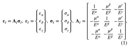
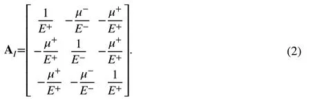
To ensure that AIis a symmetric matrix,+∕E+=_∕E-is required.
2.2 Generalized elasticity law of bimodulus materials
It is necessary to convert the constitutive equation in the principal stress coordinates into global Cartesian coordinates. The direction cosines between the coordinate axes and principal stress directions are presented in Table 1.
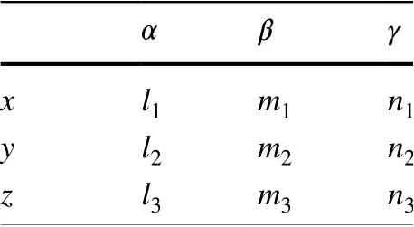
Table 1 Direction cosines between principal stress and coordinate axes
According to the formulas for the stress and strain tensors in Appendix A in the different coordinate systems, the following constitutive equation can be obtained:
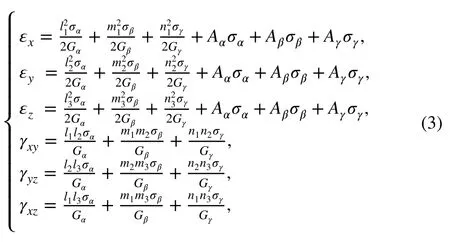
where

If the tensile and compressive moduli are equal, we have

and Eq. (3) becomes the classical Hooke’s law. If the tensile and compressive moduli are not equal, Eq. (3) is similar to the classical Hooke’s law for the first type of region. However, when σα>0 , σβ>0 , and σγ>0 , then

and when σα<0 , σβ<0 , and σγ<0 , then

For the second type of region, i.e., when σα<0 , σβ<0 , and σγ>0 , the elastic constitutive equation can be arranged as follows:
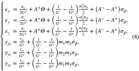
where Θ is the first invariant of the stress tensor ( Θ=σx+σy+σz=σα+σβ+σγ). It can be seen from Eqs. (3) and (8) that the constitutive equations for a bimodular material in the normal rectangular coordinate system are completely different from the classical constitutive equations. The relationship between the stress and strain is nonlinear. In addition to the familiar linear terms in the classical elastic relations, there are also nonlinear terms, as the coefficients of the linear terms are no longer constants, depending rather on the signs of the principal stress. Based on the analysis above, Eq. (3) can be arranged in the Cartesian coordinate system as follows:
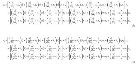
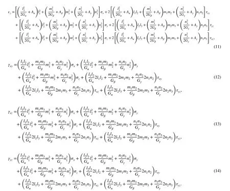
Note that, in Eqs. (9)- (14), none of the coefficients contain the principal stress or strain, so they characterize the relationships between the stress and strain in the normal rectangular coordinate system, namely the generalized elastic law. When the tensile modulus and compressive modulus are equal, we have which is Hooke’s law of classical elasticity; The other five elasticity equations can be obtained in the same way.


2.3 Discussion on mechanical properties of bimodulus problem
The stress state in a structure with bimodulus materials can be classified into three groups: (1) the three principal stresses of the point are all positive or negative, in which case the constitutive equation is the same as the isotropic constitutive equation; (2) the signs of the three principal stresses are not the same, but the principal stress direction is exactly the same as the coordinate axis direction, so the constitutive equation of this point can be simplified to the original constitutive equation defined in Eq. (1), which is similar to the constitutive equation of orthogonal anisotropy; (3) the signs of the three principal stresses are not exactly the same, and also the principal stress direction does not

3 General shear modulus and complemented algorithm in 3D case
As pointed out by Ambartsymyan, the difference between bimodulus theory and classical linear elasticity theory lies in the constitutive relations. Therefore, computational strategies based on the finite element method for bimodulus materials are the same as those applied for classical elastic materials except for the elastic matrix D; in other words, only the elastic matrix D and the stiffness matrix K have to be modified.
3.1 Elastic matrix of bimodulus theory

The transformation equations between the principal stress and strain and normal stress and strain are coincide with the coordinate axis direction. Areas exhibiting such complex stress states generally account for the vast majority of the material, and the constitutive equations taken the form shown in Eqs. (9)-(14). The magnitude and direction of the principal stress in such regions are generally different. It can be seen that the generalized constitutive equations are the same in the form, but the corresponding coefficients are not equal. In the constitutive equations, the normal strains are not only related to the normal stresses, but also related to the shear stresses. In the same way, the shear strains depend not only on shear stresses, but also on the three normal stresses. Therefore, the generalized elastic constitutive equations in such regions are similar to the constitutive equations of anisotropy.
It is clear that the constitutive relations for bimodulus materials are of the linear elastic form. However, the constitutive equations of the bimodulus elastic system depend on the directions of the principal stresses. Therefore, the mechanical behavior of structures composed of bimodulus materials is a function of the stress state in the field, resulting in nonlinearity and anisotropy.
The strain energy per unit volume can be expressed in terms of the principal strains as

where DIis the elastic matrix in the principal directions (DI= AI-1, where AIis given by Eq. (1)). Substitution of Eq. (17) into Eq. (19) gives

The strain energy per unit volume can be expressed in terms of the normal strain in the Cartesian coordinate system as

Since the energy is independent of the selected coordinate system, we have

where D is the elastic matrix of the bimodulus material in the Cartesian coordinate system. Therefore, the finite element stiffness matrix in bimodulus theory can be obtained as

3.2 Shear modulus and complement elastic matrix in 3D
The constitutive equation in the principal stress coordinate system adopted in the traditional iterative algorithm is given as follows:

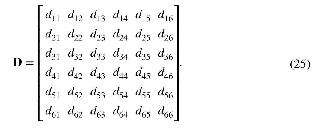
In fact, for 3D problems, the elastic matrix should be a 6 × 6 order matrix:
Since the traditional constitutive matrix does not provide values for the coefficients of the other terms, they will default to zero and the elastic matrix in the principal stress directions can be expressed as
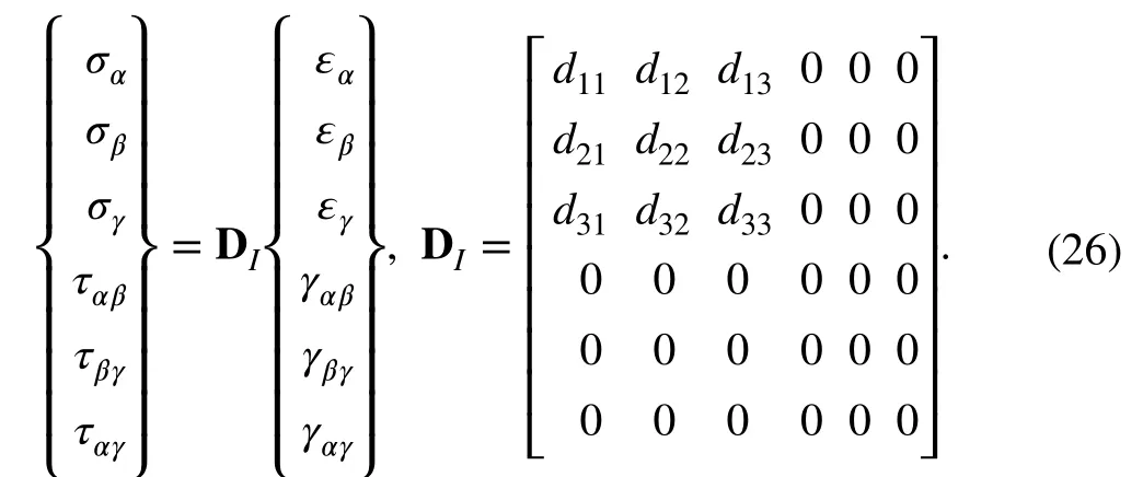
According to Eqs. (25) and (26), it is obvious that, even if the shear stress and shear strain in a principal stress direction are assumed to be zero, this does not mean that the corresponding elastic coefficient terms are zero, at least in terms of d44, d55, and d66; i.e., the so-called shear modulus is not zero. The use of an empirical shear modulus was proposed by Liu and Zhang [19] and He et al. [20] in order to improve the stability and convergence of the algorithm. However, the convergence efficiency is still unsatisfied. The reason is that the resulting shear modulus does not satisfy self-consistency.
Based on certain assumptions, the self-consistent shear modulus terms in the 3D case can be deduced by using a limit principle of the stress and strain, and such a self-consistent 3D complemented algorithm is proposed herein. The proposed algorithm exhibits efficient convergence efficiency for general cases and can be easily implemented using commercial finite element software.
It is assumed that the elastic matrix in a principal stress direction for bimodulus problems has the same form as orthogonal anisotropy and that the principal stress axis is coincident with the principal strain axis. Then, the elastic matrix and flexibility matrix based on the principal stress direction gives
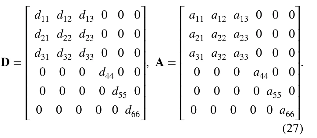
It can be seen from elastic mechanics and the matrix principle that D = A-1, d44= 1/a44= Gαβ, d55= 1/a55= Gβγ, d66= 1/a66= Gαγ. Gαβ, Gβγ, and Gαγare the shear moduli in the principal stress directions. However, since it is assumed that the principal strain axis is coincident with the principal stress axis, both the shear stress and shear strain are zero.
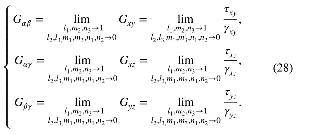
Assuming that the axes x, y, and z tend to be the axes α, β, and γ, respectively, we have
According to the rotation formula for stress and strain,

When the coordinate axis changes by an infinitesimal angle from the principal stress direction, the corresponding direction cosines suffer an infinitesimal change, and the new direction cosines yield l1, m2, n3→ 1, l2, l3, m1, m3, n1, and n2→ 0.
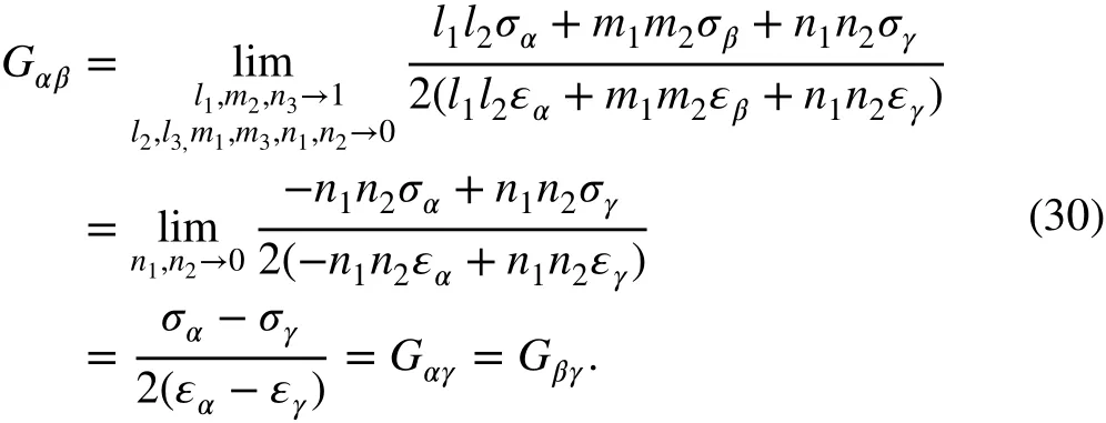
When σα=σβ≠σγ, the cosine equations yield l1l2+m1m2+n1n2=0 , thus n1n2=-(l1l2+m1m2) . Equation (28) gives
Similarly, if σα≠σβ=σγ, thenα=β≠γ, and one has

If σα=σγ≠σβ, thenα=γ≠β, and one has

If σα≠σβ≠σγ, thenα≠γ≠β, and we have
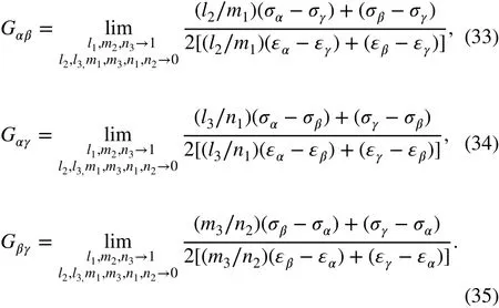
The ratios l2∕m1, m3∕n2, and n1∕l3are proved to be -1 in Appendix B. Substituting these values into Eqs. (33)-(35) then yields

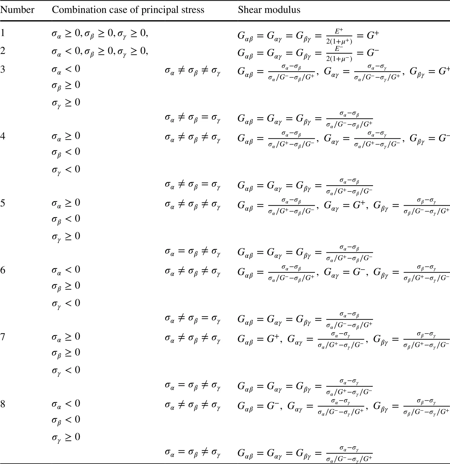
Table 2 Shear moduli in eight types of principal stress state

There are eight cases of shear modulus in principal stress coordinates, as presented in Table 2.
When σα=σγ=σβ, the stress state if hydraulic, which is discussed in Sect. 2.1; the shear moduli are then proved to be G+and G-, respectively.
3.3 Complemented algorithm with FEM
3.3.1 Finite element calculation process
Because the bimodulus problem is nonlinear, as all the elastic parameters in the field are functions of the stress state, an iterative technique is employed in this work. By using the results from the previous calculation, the principal stress state is specified to determine the elastic matrix for the next step of iteration. The iteration format is as follows:

where Ki-1is the global stiffness matrix in the (i - 1)th iteration step, uiis the current displacement matrix, and F is the vector of the force term.
The iterative calculation can be described as follows:
Step 1: Set the mechanical property of the structure as one modulus; i.e., the initial elastic parameters of the structure are specified as in a state of either full tension or full compression (where the initial elastic matrix is D+or D-), then calculate the stresses and strains in each element.
Step 2: Determine the principal stresses and their directions at each Gaussian integral point. Based on the principal stresses at each integral point, determine the compliance matrix A in the principal stress direction. Then, obtain the corresponding elastic matrix D of bimodulus theory by using Eq. (22) and Table 2, and the stiffness matrix K by using Eq. (23).
Step 3: Calculate the stresses and strains of each element according to the new stiffness matrix.
Step 4: Calculate the displacement difference of each node or the stress difference of the unit integral point at the (i + 1)th and ith iteration. If convergence is satisfied, the calculation is completed, Otherwise, let i = i +1, and go to step 2 for the next iteration.
The calculation procedure is described in the flowchart shown in Fig. 1.
The convergence criterion can be defined based on:
1. The difference between the displacement at time i and time i + 1 at each node, namely

2. The difference between the stress at time i and time i + 1 time at each node, namely

Previous work [6, 20] has shown that the difference between these two control methods is very small.
3.3.2 Implementation of complemented algorithm in ABAQUS
Based on the tangent algorithm [6], the 3D complemented algorithm is developed with the UMAT subroutine in ABAQUS. Since ABAQUS adopts the displacement method, namely taking the displacement as the unknown variable, the strain is transmitted to UMAT. Therefore, ABAQUS should judge the stress combination according to the following principles or formulas:
According to Eq. (1), we have
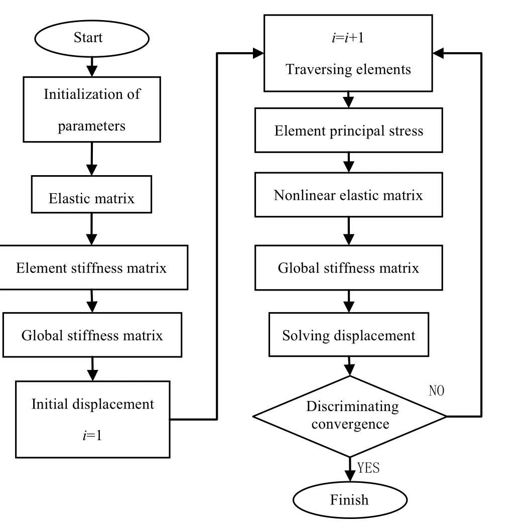
Fig. 1 Flowchart of calculation for bimodulus problem

1. When σα≥0 , σβ≥0 , and σγ≥0,
Let Δ1=; then we have


In the same way, the discriminant inequality of the remainder cases can be obtained as follows:
2. When σα<0 , σβ<0 , and σγ<0,

3. When σα<0 , σβ≥0 , and σγ≥0,

5. When σα≥0 , σβ<0 , and σγ≥0,

6. When σα<0 , σβ≥0 , and σγ<0,

7. When σα≥0 , σβ≥0 , and σγ<0,

8. When σα<0 , σβ<0 , and σγ≥0,

By observing the principal stresses, one can determine the shear modulus based on Table 2, then obtain the compliance matrix A. Considering DI= A-1, the elastic matrix DIcan be obtained. Finally, the elastic matrix D in global coordinates for a bimodulus material can be obtained as


4. When σα≥0 , σβ<0 , and σγ<0,
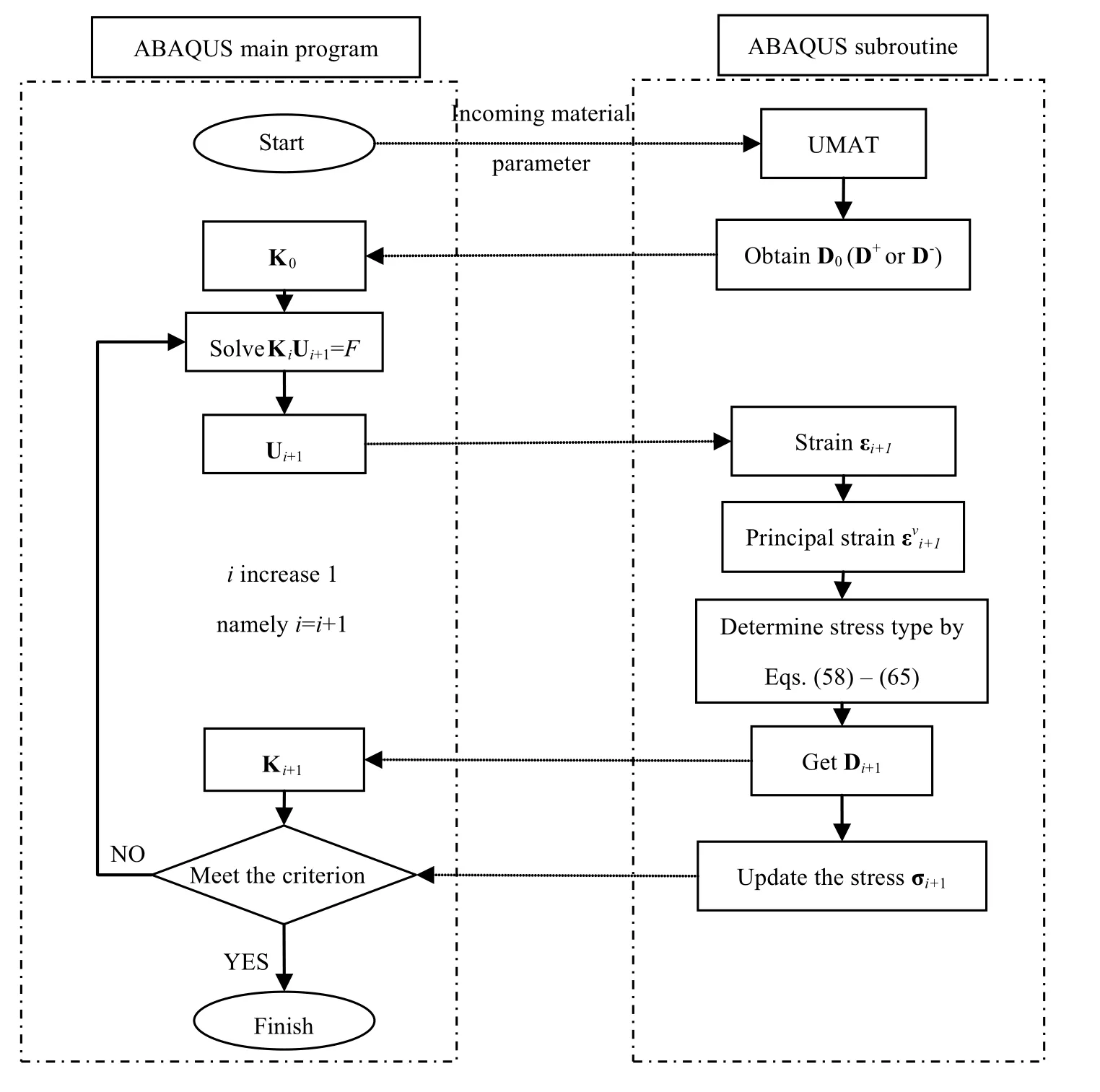
Fig. 2 Calculation principle of complemented algorithm as applied in ABAQUS
The subsequent steps are the same as for classical elasticity. The flowchart using UMAT in ABAQUS is shown in Fig. 2.
The convergence criterion of ABAQUS is multiindex comprehensive control, in which the maximum iterative residual internal force Raand displacement correction caplay a major control role. The default convergence criteria in ABAQUS are that Rabe smaller than 0.5% of the average force on the structure and cabe less than 1% of the total incremental displacement ‖Δu‖ , which are defined as

It has been shown that, when the computation converges, ‖Δu‖ is generally less than 10-8when using the ABAQUS default convergence criterion. The accuracy requirements are fully met, and the error between the results calculated in this paper and those in existing literature is minimal. Therefore, the subsequent analysis in this paper adopts ABAQUS software’s default convergence criteria.
4 Numerical examples
4.1 Tensile column with gravity
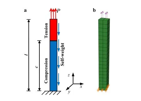
Fig. 3 Analysis of a tensile column with gravity: a force schematic diagram; b 3D finite element model
As shown in Fig. 3, the length of the column l is 10 m and the cross-section is 1 m × 1 m, being built from 3D linear integrator elements (C3D8). The uniformly distributed load P is 6 Pa, and the self-weight of the material per unit volume γ is 2 N/m3. The fixed compressive modulus E-is 5000 Pa, and the tensile Poisson’s ratio and compressive Poisson’s ratio are both zero. The ratio of the tensile modulus is a free variable.
According to Ref. [4], the analytical solution for the vertical displacement at any point along the z direction of this column is

In Eq. (55), c=l-p∕γ , i.e., the demarcation point of the tensile and compressive stresses in the column. The calculation results are presented in Table 3, and the iteration numbers are presented in Table 4.
4.2 Door-shaped frame with gravity
Consider a 3D door-shaped structure with gravity. The boundary conditions and dimensions of the structure are shown in Fig. 4. The bottom is fixed, and 384 C3P8 linear elements are used in total. For convenience of comparison, the same material parameters are adopted as in Ref. [23], i.e., compressive modulus E-of 1800 MPa and compressive Poisson’s ratio of 0.3. Then the tensile modulus E+and tensile Poisson’s ratio μ+satisfy μ+/E+= μ-/E-. The computational results and convergence efficiency are presented in Table 5 and Fig. 5, respectively.
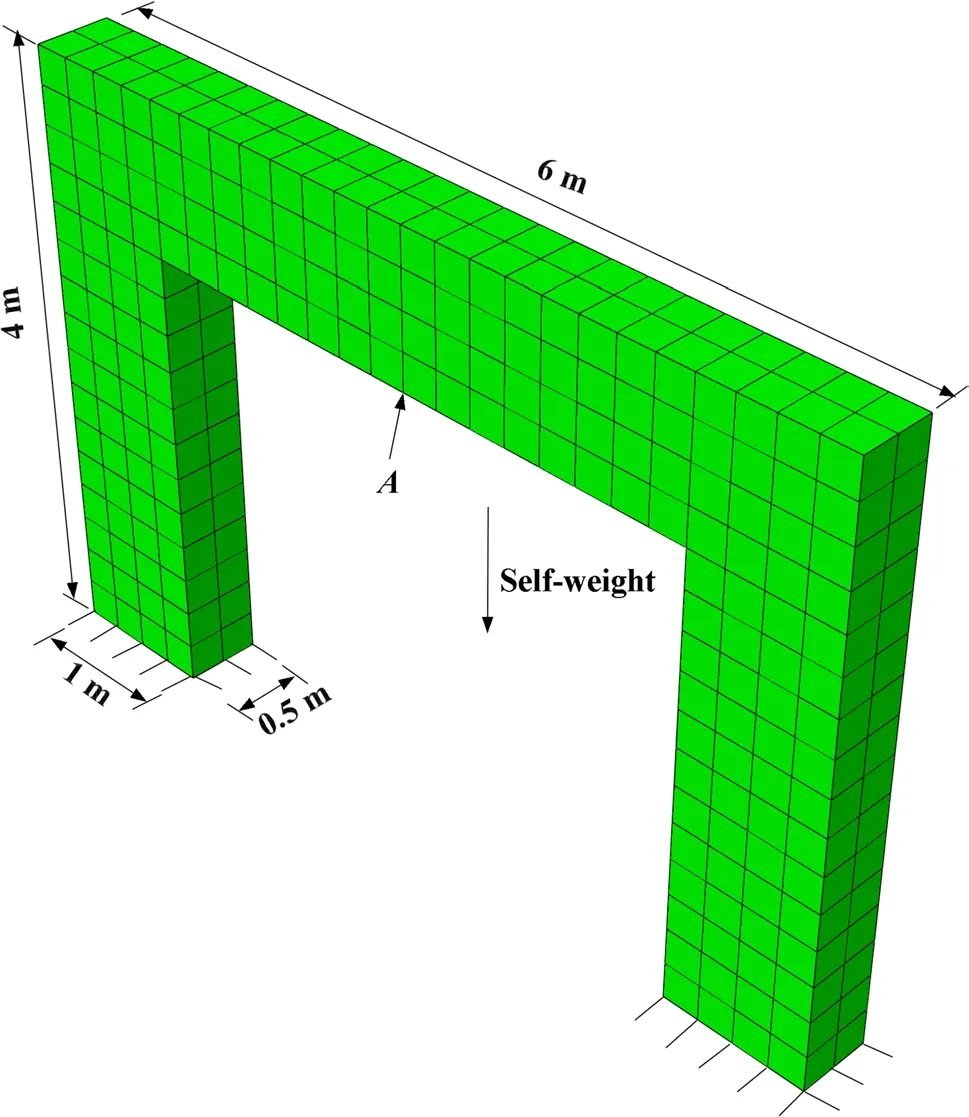
Fig. 4 Sketch of a door-shaped frame

Table 3 Comparison between numerical and analytical solutions for the displacement
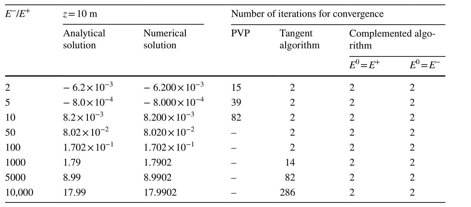
Table 4 Iteration numbers of different algorithms
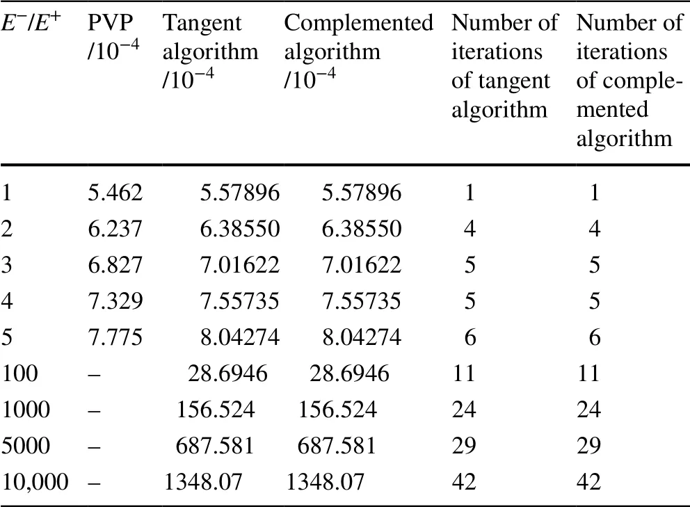
Table 5 Comparison of calculation results for different E-/E+ ratios
The numerical results of these two examples are in excellent agreement with literature. In addition, compared with the PVP algorithm, it can be seen from Table 5 and Fig. 6 that the complemented algorithm requires fewer iterations and shows faster reduction of the iteration tolerance and high convergence efficiency. Table 4 shows that the number of iterations required to complete the algorithm is exactly the same for different initial guesses. When the difference between the tensile and compressive moduli is small, the complemented algorithm is not very different from the tangent algorithm. Otherwise, the convergence efficiency of the complemented algorithm is slightly better than that of the tangent algorithm. We checked the iteration history of the tangent algorithm, finding that, when E-/E+is greater than 1000, the stiffness matrix of the structure has negative eigenvalues during the iteration process in example 1, whereas the complemented algorithm does not. This may be the reason why the number of iterations for the tangent algorithm increases in some cases. In addition, the tangent algorithm requires the derivative of the elastic matrix in order to obtain the tangent modulus matrix, which is a complicated and tedious process. However, the complemented algorithm can be calculated directly and is easy to implement.
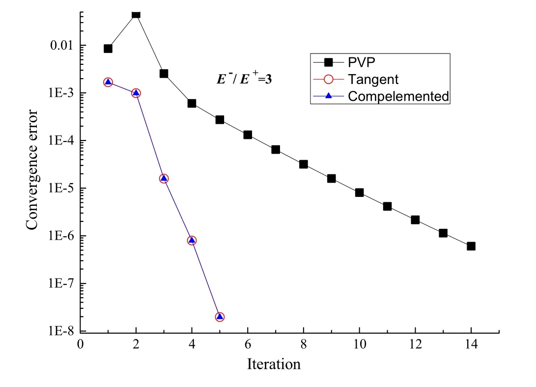
Fig. 6 Displacement tolerance convergence curves of three algorithms when E-/E+ is 3
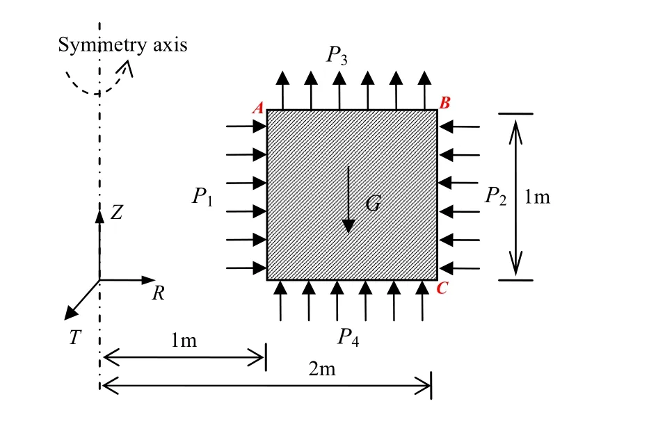
Fig. 7 Structural force and its size
4.3 Hollow cylinder with gravity
The hollow cylinder shown in Figs. 5 and 7 has an inner diameter of 1 m, outer diameter of 2 m, and height of 1 m. The inner pressure P1is 2 Pa, the outer pressure P2is 1 Pa, and the uniform tension P3and pressure P4are both 1 Pa. The self-weight of the material per unit volume γ is 2 N/m3. Cylindrical coordinates (where R is the radial direction, T is the circumference tangent direction, and Z is the axial direction) are adopted for the calculation. The compressive modulus is selected as 100 kPa, and the compressive Poisson’s ratio as 0.2. The ratio (ω) of compressive modulus to tensile modulus is variable.

Table 6 Comparison between numerical solution and analytical solution (*) of strain
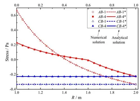
Fig. 8 Variation of tangential stress (σT) along AB and CB (ω = 1 and ω = 4)
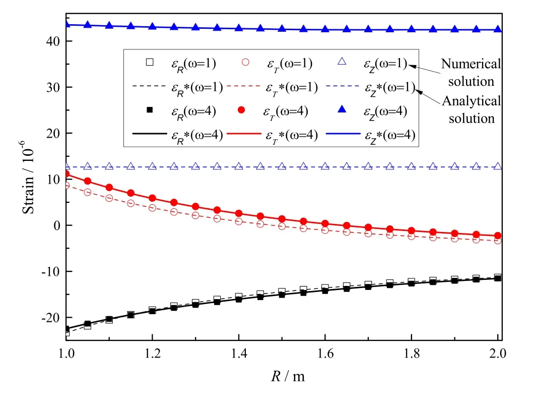
Fig. 9 Variation of strain along AB (ω = 1 and ω = 4)
Numerical and analytical solutions (*) [4] for the tangential stress (σT) and tangential strain (ƐT) along AB are presented in Table 6, while the variation of the strains with the coordinates for different ratios ω is shown in Figs. 8, 9, and 10.
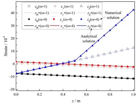
Fig. 10 Variation of strain along CB (ω = 1 and ω = 4)
It can be seen from the results presented in Table 6 that the numerical solution for the strain in the hollow cylinder is consistent with the analytical solution with a very high degree of accuracy. Figures 8, 9, and 10 reveal huge differences between the calculation results obtained when using the compressive modulus (ω = 1) and the bimodulus (ω = 4); Indeed, the tangential strain ƐT(ω = 4) along CB is four times the tangential strain ƐT(ω = 1), and the nonlinear law of the radial stress σTon AB and the axial strain ƐZon CB are obvious. Therefore, bimodulus theory should be used to calculate the mechanical response of bimodulus structures in engineering, to avoid large errors.
5 Conclusions
Based on the bimodulus theory established by Ambartsumyan, the relationships between stress and strain in the general rectangular coordinate system are studied, and a simple efficient numerical algorithm for application to 3D bimodulus structures is proposed. The following main conclusions can be drawn:
1. The constitutive equations of bimodulus theory in the general rectangular coordinate system, namely the generalized elastic law, are derived. Through analysis of the generalized elastic law, the anisotropy and nonlinear characteristics of structures composed of bimodulus materials are observed.
2. The general 3D shear modulus formula in the principal stress directions is deduced, and a theoretical self-consistent complemented algorithm is proposed.
3. The 3D complemented algorithm is implemented in ABAQUS using the UMAT subroutine. The calculation results show that the algorithm is simple and exhibits good stability and convergence efficiency.
The numerical results show that different ratios of the tensile and compressive properties of bimodulus materials have a significantly influence on the mechanical response of the structure. Dynamic analysis with bimodular materials will be investigated in future work.
AcknowledgementsThe authors highly appreciate Prof. X. Guo and Dr. Z.L. Du from Dalian University of Technology for helpful discussion and advice. This research was supported by the National Natural Science Foundation of China (Grant 51908071), Scientific Research Project of Education Department of Hunan Province (Grant 18C0194), and Open Fund of Key Laboratory of Road Structure and Material of Ministry of Transport, Changsha University of Science & Technology (Grant kfj170303).
Appendix A
Deduction of the constitutive equation Eq. (3)
The direction cosines obey the following relationships:
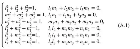
The strain components in one coordinate system are given as

Substitution of Eq. (1) into the constitutive Eq. (A.2) yields
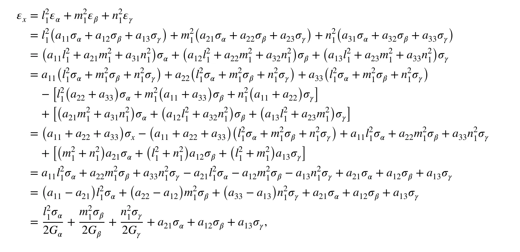
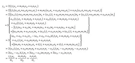
Similarly, the remaining equations can be obtained in the same way.
Appendix B
The ratios l2∕m1 , m3∕n2 , and n1∕l3
Note that the direction cosines satisfy the following equations:

When l1, m2, n3→ 1; l2, l3, m1, m3, n1, n2→ 0, we have

From Eqs. (a) and (d) in (B.2), we have

and from Eqs (b) (c) in (B.2), it is obvious that

Similarly, from Eqs. (e) and (f) in (B.2), one has

Combining Eqs. (B.3)-(B.5) and lettingl2∕m1=k , we have

From Eqs. (B.3) to (B.6), it can be seen that the three shear moduli have similar form to k. Consider
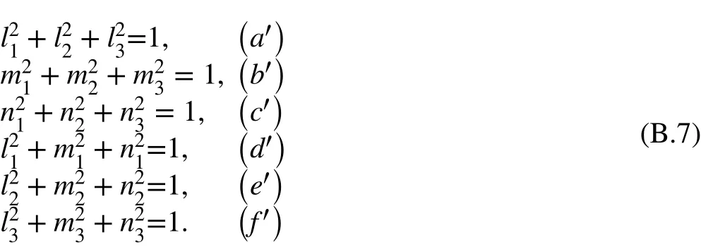
Equations (a′) and (d′) give

Substitution of Eq. (B.6) into the above equation yields

Thus

Similarly, from Eqs. (b′) and (e′), we have

and from Eqs. (c′) and (f′)

Combining Eqs. (a′) and (e′) and taking the limits, we obtain

Similarly, from Eqs. (a′) and (f),

small quantities of the same order, as are l2, n1, and m3. In addition, the limit can be obtained as
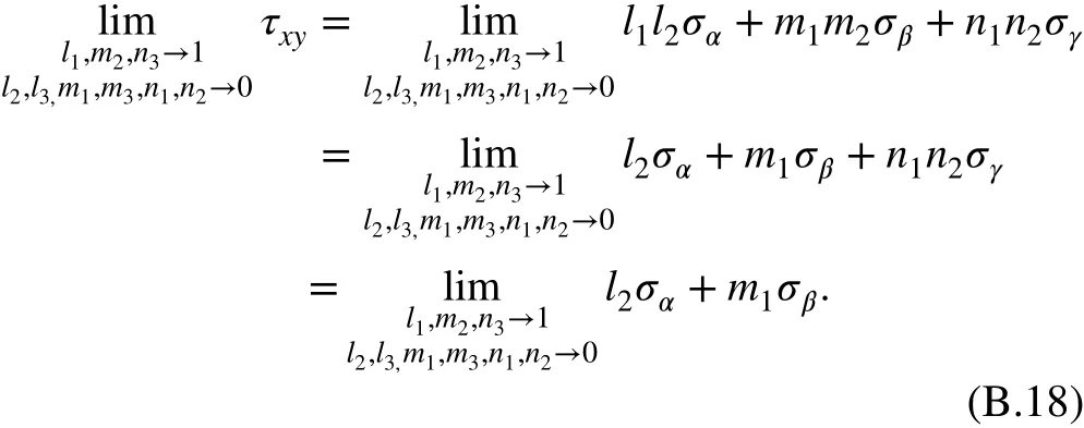
As the shear stress is zero on the principal stress surface, i.e.,
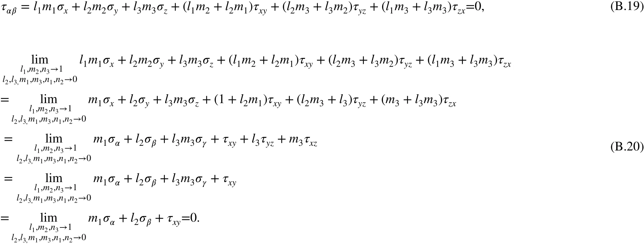
and from Eqs. (b′) and (d′) and from Eqs. (b′) and (f′),

Also, from Eqs. (c′) and (d′) and from Eqs. (c′) and (e′), one has

Considering Eq. (B.6), Eqs. (B.8)-(B.16) yield

It can be seen from the above formula that the direction cosines have the same signs (positive or negative) or different signs at the same time. l3, m1, and n2are infinitesimally
Then, it can be obtained from Eqs. (B.19) and (B.20) that

Combining Eqs. (B.18) and (B.21) yields

Therefore, we have

Since the above equation is true for any magnitude principal stresses σαand σβ, one haswhich leads to

In the same way, we have

杂志排行
Acta Mechanica Sinica的其它文章
- Geometric and material nonlinearities of sandwich beams under static loads
- Coupled thermoelastic theory and associated variational principles based on decomposition of internal energy
- Transient growth in turbulent particle-laden channel flow
- Experimental and theoretical investigation of the failure behavior of a reinforced concrete target under high-energy penetration
- Revealing the high-frequency attenuation mechanism of polyurea-matrix composites
- Generalized stiffness and effective mass coefficients for power-law Euler-Bernoulli beams
