Bicycle dynamics and its circular solution on a revolution surface
2020-05-06JiamingXiongNannanWangCaishanLiu
Jiaming Xiong·Nannan Wang·Caishan Liu
Abstract In this paper,we study the dynamics of an idealized benchmark bicycle moving on a surface of revolution.We employ symbolic manipulations to derive the contact constraint equations from an ordered process,and apply the Lagrangian equations of the first type to establish the nonlinear differential algebraic equations (DAEs), leaving nine coupled differential equations,six contact equations, two holonomic constraint equations and four nonholonomic constraint equations. We then present a complete description of hands-free circular motions,in which the time-dependent variables are eliminated through a rotation transformation.We find that the circular motions,similar to those of the bicycle moving on a horizontal surface,nominally fall into four solution families, characterized by four curves varying with the angular speed of the front wheel. Then, we numerically investigate how the topological profiles of these curves change with the parameter of the revolution surface.Furthermore,we directly linearize the nonlinear DAEs,from which a reduced linearized system is obtained by removing the dependent coordinates and counting the symmetries arising from cyclic coordinates.The stability of the circular motion is then analyzed according to the eigenvalues of the Jacobian matrix of the reduced linearized system around the equilibrium position.We find that a stable circular motion exists only if the curvature of the revolution surface is very small and it is limited in small sections of solution families.Finally,based on the numerical simulation of the original nonlinear DAEs system,we show that the stable circular motion is not asymptotically stable.
Keywords Bicycle dynamics·Nonholonomic constraints·Stability·Nonlinear DAEs·Circular motion
1 Introduction
Studies on bicycle dynamics started at the end of the 19th century with the seminal work by Carvallo [1] and Whipple [2]. Since then this topic has drawn the attention from Boussinesq[3],Klein and Sommerfeld[4],Timoshenko and Young[5],and many recent researchers from different areas including classical mechanics [6-14], applied mathematics[15-17],system control[18-22],robotics[23,24],etc.Meijaard et al.[12]did a comprehensive review of the history of bicycle dynamics, and Schwab et al. [25,26] presented the state of the art of the literature.
Most of the studies focused on a benchmark model investigated by Carvallo [1] and Whipple [2], in which they simplified the bicycle as a rigid four-body system with knife-edge wheels. This benchmark model belongs to a nonholonomic system, i.e., one whose motion needs to be described using more coordinates than the dimensions of its admission velocity space.Compared to usual nonholonomic systems such as a Chaplygin sleigh[27]and a two-wheeled planar mobile robot [28], the bicycle system suffers from more difficulties in modeling its geometric constraints and motion equations.Generally,the bicycle system is subjected to two geometric constraints,which essentially are implicit and nonlinear algebraic equations. In the case where the ground is a horizontal plane,Wang et al.[29]derived a quartic algebraic equation, from which the explicit relationship between the dependent coordinates and the independent coordinates of the system can be established. When the ground takes an arbitrary surface,however,the geometric constraint equations are strongly related to the concrete expression of the ground surface, leading to difficulties for finding the explicit expressions of the dependent coordinates with respect to the independent coordinates.Another feature that has caught the interest of researchers is that an uncontrolled bicycle can balance itself at the right speed.Although there have been a lot of work to explain this intriguing phenomenon[12,13,23,30],the analyses so far are limited in a specific scenario where the bicycle moves on a horizontal surface.The objective of this paper is to investigate the dynamics and its self-stability of the benchmark bicycle moving on a surface of revolution.
How to establish the geometric constraint equations is the first challenging problem to study bicycle dynamics.Psiaki[7]applied analytic geometry to derive by hand the geometric constraints of a bicycle moving on a horizontal plane.He stated for the first time that the algebraic equations of these geometric constraints are implicit and highly nonlinear.Basu-Mandal et al.[13]derived the constraint equations based on a condition for finding the lowest points of the two wheels.A similar method was used by Peterson and Hubbard[31,32] to obtain the constraint equations of a bicycle with toroidal tires.Wang et al.[29]parameterized the two wheel profiles and used an extremum condition that the wheel-road contact should be located at the lowest point on the wheel edge.While these methods are well suited for bicycles that move on the horizontal ground, the bicycle configuration’s dependence on the ground geometry does not allow them to be used for bicycles that move on curved surfaces.
How to understand the self-stability of an uncontrolled bicycles is another challenging problem to study bicycle dynamics.Many researchers have explained the bicycle selfstability through a linear model,which is obtained by slightly disturbing the bicycle from an upright straight motion.Historically, there have been many different linearization dynamic equations, most of which were manually derived by linear approximation of the constraint equations.Neˇımark and Fufaev [8] developed a set of linearized equations that was later found to be incorrect due to an error made in their approximation of the potential energy. Papadopoulos [10]and Meijaard et al. [12] derived the linearized equations for the Whipple bicycle based on angular momentum balance. They indicated that the longitudinal dynamics of the bicycle near a stable upright straight motion ensures the forward speed to be approximately constant, while coupling between the lean motion and the steer motion exists in the lateral dynamics of the bicycle motion. Xiong et al. [33]employed the Gibbs-Appell method to derive the linearized dynamic equations of the Whipple bicycle in a near-straight motion.Noting that zero eigenvalues appear in the characteristic equations of the linearized model,they used the centre manifold theorem to strictly analyze the self-stability.Qualitative discussions on the bicycle self-stability were presented by Jones [30], Åstr¨om et al. [34] and Liu [11], etc. Some people argued that the gyroscopic action was necessary for bicycle self-stability[4],while some researchers claimed that the caster trail was the key to bicycle stability[30].Recent studies have shown that the self-stability of the bicycle are influenced by all bicycle parameters[23,35].The effects from other non-ideal factors, such as rolling resistance [36] and sideslip motion, on the self-stability were also investigated by many researchers. For example, Sharp [6] established the linearized equations with consideration of the freedom of sideslip motion.Meijaard and Schwab[37]presented an extended linearized model that takes into account the effects of tire shape,road gradient and damping term.Schwab et al.[38]considered the action of crosswind on a bicycle and concluded that crosswind can decrease the stable forward speed range of an uncontrolled bicycle. With the development of multibody dynamics computer code, various symbolic programmes have been applied to generate linear and nonlinear models [14,39-44]. Some experiments for bicycle motion were also found in recent literature for the purpose of verifying associated theoretical models[20,45].
Compared with the analysis of the rigid-wheeled bicycle’s near straight motion, the study about the bicycle’s circular motion is very little and less verifiably correct.For example,Psiaki[7]and Franke et al.[46]found one solution family of the circular motion,but Lennartsson[47]and Åstr¨om et al.[34]showed that three solution families exist in the circular motion.Basu-Mandal et al.[13]presented for the first time a complete picture of the circular motions of the Whipple bicycle.They used the Euler-Lagrange method and applied symbolic manipulation and numerical simulations to obtain the solutions of hands-free circular motions.Nominally,four different one-parameter families exist in the circular motions of the benchmark Whipple bicycle, but two of them can be merged into one, leaving three in all. Wang et al. [29]employed the Euler-Lagrange equations to derive the nonlinear benchmark bicycle model,symbolically eliminated all the constraint equations and all the constraint forces (i.e.,Lagrange multipliers),then obtained three analytic coupled second-order ordinary differential equations(ODEs).Xiong et al.[33]obtained the minimal description for the analytical nonlinear benchmark bicycle model using the Gibbs-Appell method. They both obtained the same solution families of hands-free circular motions as discovered by Basu-Mandal et al.[13].
In contrast to the case of the two wheels on the horizontal ground[13,29,31,32],the curved surface complicates the determination of the contact points [28,48], therefore the constraint equations cannot be intuitively established. Besides,the curved surface makes coordinate reduction difficult such that we cannot obtain a closed set of ODEs governing the bicycle motion. Generally, we should use the Lagrangian equations of first type to establish the governing equations in a form of a set of DAEs.The circular solutions of the bicycle motion then correspond to a set of periodic orbits in the phase space,and their stabilities,theoretically speaking,should be analyzed in the sense of Poincar´e orbital stability [49]. In order to obtain these circular solutions and analyze their stabilities in the sense of Lyapunov stability[13,17,29,33,50],we introduce a series of rotation transformations to eliminate the time-dependent variables involved in the periodic orbits, then obtain a new DAEs system whose equilibrium points correspond to the circular motions of the bicycle on the surface of revolution.Numerical investigations show that the surface parameter of ground plays a role of merging(or separating)different families of solutions.The stabilities of these circular motions are analyzed based on a reduced linearized system, which is established by directly linearizing the new nonlinear DAEs system.We find that a stable circular motion exists only if the curvature of the revolution surface is very small and it is limited in small sections of solution families.Finally,we employ the original nonlinear DAEs to simulate the dynamical behavior of the bicycle around circular motions.The numerical simulations demonstrate how an unstable circular motion cannot be remained a periodic orbit,and how a stable circular motion is not asymptotically stable.
The rest of this paper is organized as follows:In Sect.2,we use the orderly method developed by Zhao and Liu[48]to establish the constraint equations of the Whipple bicycle moving on an arbitrary surface, then apply MATLAB tool to generate the nonlinear equations based on the Lagrangian equations of the first type.In Sect.3,we use rotation transformations to eliminate the time-dependent variables involved in the circular orbits,obtain a new DAEs system governing the motion of an uncontrolled bicycle on a revolution surface,then find the circular solutions by solving the equilibrium points of the new DAEs.This model is verified by comparing the circular solutions of the bicycle moving on a horizontal surface with the results presented by Basu-Mandal et al.[13].Then we investigate how the circular motion is affected by the parameter of the ground surface. In Sect. 4, we discuss how to establish a reduced linearized system, then analyze the stabilities of the circular motions.We draw conclusions in Sect.5.
2 Constraints and dynamic equations
In this section,we will analyze the contact kinematics and local constraints of the benchmark Whipple bicycle on the ground with an arbitrary shape.Then the Lagrangian equations of the first type will be used to derive the equations of motion for the bicycle.
2.1 Configuration description
Figure 1 shows the Whipple bicycle moving on a ground.This bicycle consists of four rigid bodies including a rear frame B,a rear wheel R,a front frame H and a front wheel F.The two frames B and H have lateral symmetries in their shape and mass distributions. The two wheels R and F are circular symmetric and make ideal knife-edge rolling contact with the ground. By completely ignoring the effects of structural compliance,joint friction and rolling friction,the Whipple bicycle can be characterized by 25 geometric and mass parameters,as shown by Meijaard et al.[12]in Table 1.
We define the following coordinate systems for the bicycle: an inertial coordinate frame, FI= {O;i, j,k}, fixed on the plane, in which the i- and k-axes lie; and four body-fixed frames, Fb= {Ob;eb,1,eb,2,eb,3}, Fr={Or;er,1,er,2,er,3}, Fh= {Oh;eh,1,eh,2,eh,3}, F f ={Oh;ef,1,ef,2,ef,3},attached to the center of mass of each body,as shown in Fig.1.
Note that the four rigid bodies of the bicycle are connected by three hinges.Before we consider the wheel contact constraints,the accessible configuration space of the bicycle in a free motion is nine-dimensional (4 × 6 - 3 × 5 = 9),thus nine generalized coordinates are required. We select these coordinates as follows: the first three coordinates are related to the coordinate components,(x,y,z),of a reference point D in the frame FI. This point is located at the intersection of the steering axis and the coordinate axis O f ef,1.The second three coordinates are selected as the Euler angles,(ψ, θ, φ),for quantifying the orientation of the rear frame B with respect to the frame FI. These angles are defined by a sequence of angular rotation (312 Euler angles) as below:a yaw rotation ψ about the z-axis of FI,a lean rotation θ about the rotated x-axis and a pitch rotation φ about the rotated y-axis. The last three coordinates are selected as the steer angle δ, related to the rotation of the front frame H with respect to the rear frame B about the steering axis, and the rotation angles, φrand φf, for the rear and front wheels with respect to their respective frames.In summary, the generalized coordinates of the bicycle are defined as q = [q1,q2,...,q9]T= [x,y,z,ψ,θ,φ,δ,φr,φf]T.

Table 1 Values of the parameters of the benchmark bicycle
2.2 Geometric constraints and velocity constraints
Theoretically, the geometric constraints should be imposed over the contact interactions between the two wheels of the bicycle and the ground.Their derivation requires a detailed analysis of the geometric relationships between the bicycle configuration and the surface shape of the ground.
Suppose that the rear wheel R and front wheel F contact with the ground at points P and Q, respectively. Note that the ground surface can be parameterized by two parameters, and the profile of each wheel can be described by a single parameter. Each contact point can then be distinguished by a three-parameter set,which is denoted by pi=[pi,1,pi,2,pi,3]T, i = r, f for contact points P and Q,respectively.The first two parameters in each three-parameter set are used to identify the position of the contact point on the ground,while the last one is the position of the contact point on the edge of the wheel. Usually, the last parameter is selected as the rotation angle for distinguishing the contact point on the wheel edge.Measured from the ground and the wheels, the position vectors of P and Q in the inertial coordinate frame FIcan be written as

where function f(pi,1,pi,2) describes the shape of the ground surface.
Note that the constraints engaged into a contact point strictly depend on the surface geometries,and they should be manifested via equations established from a concrete coordinate frame[48].Referring to the geometric constraints of the bicycle,their equations will be established according to a local contact frame that is specified as follows:
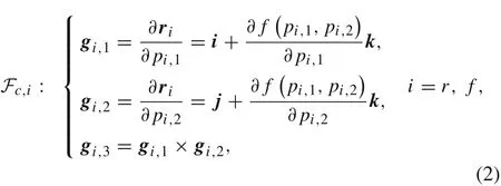
where the vectors gi,1and gi,2span the tangent plane of the ground at each contact point,and gi,3is the contact normal.
Let us define a set for the contact parameters, p =[pr,1,pr,2,pr,3,pf,1,pf,2,pf,3]T. These contact parameters closely depend on the bicycle configuration q, and the relationship between p and q can be determined via the following geometric conditions[48]:

For each contact there are four independent equations.We refer to the first,the second and the fourth equations as contact equations:

By substituting Eq.(4)into the third equation in Eq.(3)under the condition of non-vanishing Jacobian(with respect to p),wecan formulate the geometric (holonomic) constraint active at the contact point as

At a single contact,there exists only one geometric constraint locally.
Besides the geometric constraints Eq. (5), velocity dependent constraints appear in the bicycle when it purely rolls over the ground.Under rolling,the velocities at the contact points P and Q must vanish.We project these velocities on the tangent planes of the contact points and decompose them under the local contact frames,yielding the following velocity constraints,

corresponding to four scalar equations linearly depending on the generalized velocities,as shown below,

These four equations are independent nonholonomic constraints.As a result,the bicycle has three degrees of freedom in the velocity space.
2.3 Dynamics
In this paper,we mainly consider the case of an uncontrolled bicycle, thus the simple bicycle model, which is subject to two geometric constraints given by Eq.(5)and four nonholonomic constraints defined by Eq.(7),is energy-conserving.We use MATLAB tool to generate the Lagrangian function L(q,then employ the Lagrangian equations to derive the equations of motion. The fully nonlinear equations of motion include the Lagrangian equations,the geometric constraint equations and the velocity constraint equations, as well as the six contact equations,forming a set of DAEs as below,
The DAEs system Eq. (8) consists of nine second-order differential equations for dynamics, eight algebraic equations for contact parameters and geometric constraints,and four first-order differential equations for nonholonomic constraints.When solving the dynamics of the system,we need to determine 21 unknown variables,including nine generalized coordinates, six contact parameters and six Lagrange multipliers. Once the geometric parameters and physical parameters of the bicycle are given and the geometric profile of the ground surface is specified, we can use Eq. (8),with initial conditions, to numerically compute the bicycle motion.
3 Circular solutions of a bicycle moving on a revolution surface

3.1 Description of the circular motion
In this section, we investigate the circular solutions of the bicycle moving on a revolution surface.Without loss of generality,we specify the surface as a paraboloid of revolution,which takes a mathematical form as,ζ =α(ξ2+η2),where α is a parameter of the ground surface.The circular motions of the bicycle on the surface,similar to the case of the bicycle on a horizontal plane[13,29,33],correspond to periodic orbits of the DAEs system Eq.(8).Thus,x and y vary sinusoidally and z is constant.Namely,the reference point D(see Fig.1)traverses a circle with radius(say)R1.We designate the angular frequency of the circular motion as ω,so the first Euler angle(heading)ψ grows linearly with time,i.e.,ψ(t) = ωt.The second Euler angle(roll)θ,the third Euler angle(pitch)φ,the steering rotation angle δ and the wheel spin rates ˙φrand ˙φ f are all constants. It is worth noting that the rotations (φr,φf)of the two wheels relative to their respective frames are ignorable coordinates that do not appear in the Lagrangian function and constraint equations [12]. Therefore, the state of the circular motion can be described as follows,

where ∈1is the initial phase angle as ψ(t)=0.Obviously,a complete description for the circular motion requires 9 constants including R1,∈1,z0,ω,θ0,φ0,δ0,ωrand ωf.
Besides,we need to describe the contact parameters as the bicycle is in the circular motion. It isworth noting that the herpolhodes of the two contact points on the revolution surface correspond to two different circles. Therefore, the surface parameters(pi,1, pi,2)in connection with the position of the contact on the revolution surface should vary periodically.Additionally, we define ϑi= pi,3(q) + φi, i = r, f, to replace the parameters used for describing the positions of the contact points on the wheel edges.Due to the geometric conditions of the contact, parameters ϑi(t) should be kept unchanged when the bicycle is in the circular motion.Then we can describe the six contact parameters as follows,

in which ∈2and ∈3are the initial phase angles in connection with the periodic-variable parameters.Therefore,as the bicycle is in the circular motion,the contact parameters correspond to six constants including R2,∈2,R3,∈3,ϑ0rand ϑ0f.
Note that the Lagrange multipliers in Eq.(8)correspond to the constraint forces induced by the contact constraints.In particular, λr,3and λf,3are the normal components of the constraint forces of the rear and front wheels, respectively.While these two Lagrange multipliers are kept unchanged in the circular motion, the remaining multipliers should vary periodically.Therefore,the six Lagrange multipliers take the following form,

in which ∈4and ∈5are two initial phase angles related to the periodic-variable multipliers, and there are 6 constants needed to be determined.
In summary, we require 21 independent constants to describe the circular motion of the bicycle on the revolution surface. However, when Eqs. (9)-(11) are substituted into Eq. (8), it is inconvenient to obtain these 21 constants because time t appears explicitly in the expression of the circular solution.In order to eliminate these time-dependent variables,we define a rotation transformation matrix as follows:

By using matrix T,we transfer the time-dependent variables in the circular motion as follows,
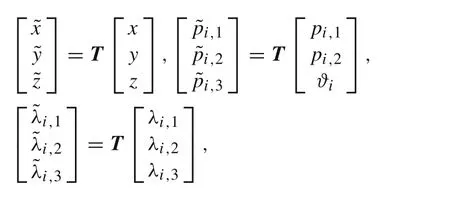
where i = r, f. Meanwhile, the original DAEs system Eq.(8),after the rotation transformation,becomes

Note that φrand φfare two cyclic coordinates that cannot appear in Eq.(13).Due to the rotation symmetry of the ground surface, the Lagrangian and constraint distribution of the bicycle system should be invariant under the action of the Lie group S1[16]. Meanwhile, S1also allows all coordinates in ˜q,except ψ,to be kept unchanged.Therefore,ψ must be the cyclic coordinate of the new system Eq. (13),leading to six non-cyclic generalized coordinatesIt is worth noting that, although the three cyclic coordinates do not appear in the description of the circular motion,their time derivatives should be included.Therefore,the circular motion requires nine kinematic constants,six for generalized coordinates(),and three for generalized speeds(ω, ωr, ωf). Besides, we useandto denote the six contact parameters and six Lagrange multipliers in the circular motion,respectively.Obviously,the values ofandshould also be constants.Totally,there are 21 constants for characterizing the bicycle’s circular motion. However, the circular solutions,similar to those of the bicycle moving on a horizontal plane [13,29,33], will fall into one-parameter families. Namely, there is a free parameter among the 21 constants. In the following, we select the angular velocity of the rear wheel (ωr) as the free parameter to numerically investigate the circular solutions of the bicycle moving on the revolution surface.
3.2 Validation of the model
We set the ground surface parameter α =0,corresponding to the situation where the bicycle moves on a horizontal ground.This case is used to check the accuracy of our model by comparing with the results given by Basu-Mandal et al.[13].The bicycle parameters are shown in Table 1,corresponding to the Whipple model described in Refs.[12,13].
For finding the circular solutions,we first give the value of ωr, then use the algebraic equations degenerated from Eq. (13) to find the values of other constants. The solution families can then be obtained by continuously changing the rotation speed of the rear wheel in a range ωr∈[0,+∞).Considering the lateral symmetry of a bicycle, we just solve the circular solutions by limiting the steer angle in a range δ0∈[0,π]. Following Basu-Mandal et al. [13],we describe the circular solutions by plotting the curves of the lean angle θ0and the steer angle δ0with respect to arctan(R f ωf/4),i.e.,the scaled front wheel speed.
Figure 2 shows that there are four families of circular motions in the case of α = 0. The first solution family is related to the curvewhere the steer angles in this family are limited in a range δ0<π/2.Points A corresponds to a static equilibrium of the bicycle with a configuration δ0=1.33973991149, and point B represents an upright straight motion of the bicycle with a limit speed ω f ≈17.2 rad/s.
For the second solution family, its steer angles are limited in a range δ0>π/2 and the angular velocities of the front wheel are always negative.Therefore,we plot this family as the curvein Fig.2,where the x-coordinate for this family represents-arctan(R f ωf/4).Point C represents the upright straight motion with the handlebar completely reversed (δ0= π) and ωf≈-22.6 rad/s. Point D is a cusp point with(θ0,δ0,ωf)≈(0.62,2.78,-14.6).Around this point,θ0and δ0take multiple values under a given ωf.Point E represents a limit situation where a triple(θ0,δ0,ωf)tends to(π/2,π,-∞).
The third solution family is related to the curvein Fig. 2. Point G represents a motion that the bicycle with a configuration(θ0,δ0) ≈(-0.01206,1.6019)rotates around a vertical axis passing through the rear wheel contact point P, and its front wheel takes an angular velocity ω f ≈6.19 rad/s.In this motion the angular velocity of the rear wheel is nearly equal to zero.Point F,similar to point E,corresponds to a limit situation where a triple (θ0,δ0,ωf)tends to(-π/2,0,∞).In this family,the lean angle and the steer angle monotonically decrease with the increase of ωf.
Figure 2 also contains the four solution families found from Ref. [13], which are represented by a series of discrete black dots.Excellent agreement between the numerical results obtained from different methods confirms that our model is correct and our numerical simulation is accurate.
3.3 Variation of the circular solutions with ground parameter
Now we investigate how the circular solutions change with the ground parameter α.Figure 3 presents four solution families obtained by setting α = 1/200. There is one static equilibrium state denoted by point A and a pivoting motion denoted by two merged points G and H.In comparison with the case of the horizontal ground,the small α makes the static equilibrium state and the pivoting motion change little,and the curves of θ0and δ0with respect to arctan(Rfωf/4)are very similar to those of the bicycle on the horizontal ground.
According to our numerical investigations,we find that at a right value of α the cusp point D in the second solution family will be merged with the cusp point I in the fourth solution family.Before the critical value of α, the two solution families approach each other accompanying the increase of α.When α is larger than the critical value,however,the two families separate from each other in another direction. The evolution of the two curve profiles with α is very similar to a process of“collision and split”between the second and fourth solution families.Figure 4 shows the four solution families for the case of α =1/20.In comparison with those of α =0,the curve profiles of the first and the third solution families change little,but the second and the fourth solution families take new curve profiles due to the“collision and split”of the two families.Particularly,the cusp points D and I disappear in this case.Figure 5 shows the circular solutions in the case of α =1/5,which are very similar to those of α =1/20.
In order to create an intuitive impression for the circular motions,Fig.6 shows the bicycle configurations for four specific circular solutions, each selected from a different solution family of the case of α =1/5(see Fig.5).Figure 6a shows the bicycle configuration of the circular solution in the first solution family at point P1(θ0,δ0,ωf≈-0.42,0.63,10.49).In this case, the bicycle moves anticlockwise (˙ψ > 0)and takes a configuration with a small lean angle and a forward-direction handlebar. Figure 6b shows the bicycle configuration of the circular solution in the second solution family at point P2(θ0,δ0,ω f ≈0.86,2.75,-19.25).In this situation,the bicycle moves clockwise(˙ψ <0)and takes a configuration with a large lean angle and a reversed direction handlebar. In addition, the rear and front wheels rotate in opposite directions. Figure 6c shows the bicycle configuration of the circular solution in the third solution family at point P3(θ0,δ0,ω f ≈-0.87,0.40,19.10). The bicycle configuration is similar to that of point P1, except that it has a large lean angle. Figure 6d shows a bicycle configuration in the circular solution of the fourth family at point P4(θ0,δ0,ω f ≈0.18,1.97,-9.70). In this case,the bicycle moves in a clockwise handlebar-reversed circular motion with a small radius.
We also investigate the circular solutions when the ground surface parameter is large enough.Generally,the curve profiles of four solution families will change a lot,but one static equilibrium state and one pivoting motion still exist.Figure 7 shows the four families in the case of α =1,where the static equilibrium state and pivoting motion are located at points A and G(H),respectively.Particularly,the third solution family, in addition to merging with the fourth solution family at point G, is also merged with the first solution family at point B. Therefore, we can consider that the first, the third and the fourth solution families are merged into a combined family.
4 Stability analysis
4.1 Reduced set of linearized equations
By using the rotation transformation,we have transferred the bicycle’s circular motion as the equilibrium point of system Eq.(13),from which four solution families can be obtained.The stability of each point in these families can now be discussed with the Lyapunov stability of the system equilibrium point[32,51].For this purpose,it is necessary to have access to the linearized system dynamics of the DAEs system Eq. (13). Basically, there are several methods to arrive at linearized forms of dynamics equations, but the method choice affects the accuracy and computational efficiency of the linearization process [14,52,53]. Here, we use the Taylor expansion series to directly linearize the DAEs system Eq.(13),in which the Lagrange multipliers and the contact parameters are taken as variables to be linearized[54,55].
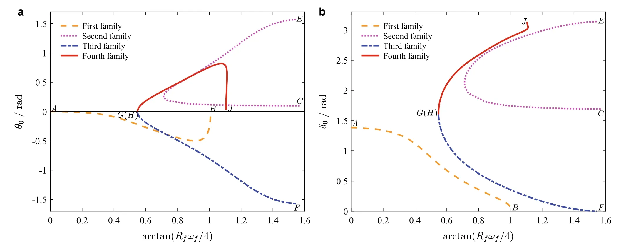
Fig.4 α =1/20.Curves of a θ0 and b δ0 parameterized with arctan(R f ω f/4)
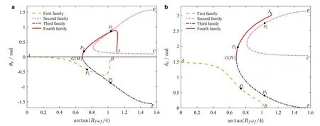
Fig.5 α =1/5.Curves of a θ0 and b δ0 parameterized with arctan(R f ω f/4)

Fig.6 Configuration of the bicycle in a circular motion of a the first,b the second,c the third,and d the fourth solution family
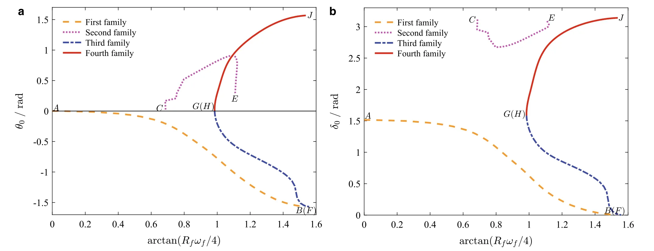
Fig.7 α =1.Curves of a θ0 and b δ0 parameterized with arctan(R f ω f/4)
We denote the equilibrium point by the following constant vectors:andSuppose that the equilibrium point is disturbed by small variables,and. The firstorder linearized system of the DAEs Eq.(13)casts into the following form,
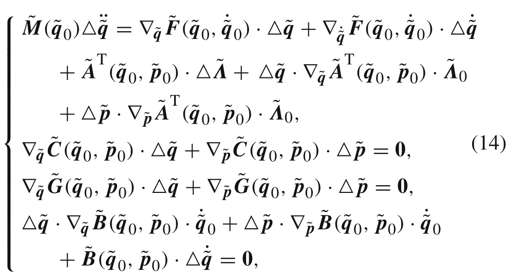
where ∇(·)is a gradient operator about variable(·).
where E and H can be identified in(14).Matrix E is structurally singular, thus the system Eq. (15) cannot be solved with a standard eigenvalue analysis[54,55].Usually,one can use the method of generalized eigenanalysis to obtain the eigenvalues of Eq. (15), but this method introduces spurious eigenvalues [56]. Peterson et al. [14] indicated that, in the case of eigenvalues computations, a reduced set of linearized equations should be used,especially for the systems with nonholonomic constraints.
In order to obtain a reduced set of the linearized equations,we need to classify how many quantities are independent.In the configuration space,the DAEs system Eq.(13)is subject to two geometrical constraints.This means that the configuration can be fully described by seven independent coordinates.We choose the independent generalized coordinates asθ, δ, ψ, φr, φf. In addition, we know that ψ, φrand φ f are three cyclic coordinates that cannot appear in the motion equations of the system.Therefore,the DAEs system Eq.(13)only consists of four independent coordinates:θ and δ.In the velocity space,the system is subject to four nonholonomic constraints.Therefore,the velocity space can be fully described by choosing three independent velocities, which are denoted as
The above discussion indicates that the DAEs system Eq. (13) essentially can be transformed into a reduced system consisting of 7 first-order ordinary differential equations. As the independent variables are selected as v =we can write the reduced system as

where X :D →T D is a smooth vector field on D ⊂R7.
Theoretically speaking, the equilibrium points of the reduced system, designated as v*, can be obtained by setting X(v*) = 0, and they should be equivalent to those obtained by the DAEs system Eq. (13). Thus, the equilibrium points should take the following structure: v*=. The linearized equations of the reduced system Eq. (16) around v*can then be expressed as

Actually, the reduced linearized system Eq. (17) can be generated by removing the linearly dependent variables in(14).For instance,we can use the second and third subsets of equations in Eq. (14) to expressand the two dependent coordinates △z and △φ as the linear combinations of the independent coordinates, △θ and △δ. Accordingly,we can use the last subset of equations in Eq.(14)to express △and △as the functions of △v. Similarly, the first subset of equations in Eq. (14) can be used to remove the dependent coordinates and the Lagrange multipliersthus we can expressandas linear functions of △v.
Once the reduced linearized system is established,its Lyapunov stability can be analyzed according to the eigenvalues of J at v*. Noting that the solutions of the equilibrium points fall into a set of one-parameter curves, the Jacobian matrix J at v*must have at least one zero eigenvalue.In this case,a stable equilibrium point v*is not asymptotically stable according to the centre manifold theorem of differential dynamic system[33,57,58].
4.2 Numerical results
We employ the reduced linearized system Eq.(17)to numerically investigate the stability of the circular motion and conclude the results as follows:
· For the Whipple bicycle in the case of α = 0, we get the same results as discovered in Ref.[13].Namely,only small sections of the circular motions neighboring the cusp points D and I (see Fig.2)are Lyapunov stable.
· In the case of α =1/200,only a small section of the circular motions neighboring the cusp point D in the second solution family(see Fig.3)are Lyapunov stable.
· When α is large enough,i.e.,α =1/20,1/5,1,all of the circular motions in the four solution families are Lyapunov unstable.
In order to demonstrate the stable and unstable behaviors of the bicycle in circular motions, we select two points Q1and Q2(see Fig. 3) in the solution curves of α = 1/200.Point Q1corresponds to an anticlockwise handlebar-forward circular motion in the first solution family, relating to an equilibrium point of the reduced system Eq. (16) at v*1=[0.99,-6.77,-0.39,0.14,0,0,18]T. The Jacobian matrix at v*1is given by

The computed eigenvalues of J1are as follows:0,-13.40,0.38,-1.73±5.73i,-0.01±0.98i.Clearly,J1has a zero eigenvalue,agreeing with the basic feature of the bicycle in the circular motion.In addition,there is an eigenvalue whose real part is positive.Therefore,we can conclude that point Q1is Lyapunov unstable.The unstable behavior can be demonstrated by numerically simulating the motion of the bicycle using the original nonlinear DAEs system Eq. (8). We set the initial conditions of the independent variables coinciding with the values specified by the equilibrium point v*1,and make the initial values of other dependent variables in Eq.(8)satisfy the relevant constraint equations.The modified Euler method with a time step △t =0.001s is chosen for the numerical simulation.Figure 8 shows the numerical results for the trajectory of the reference point D of the bicycle on the x-y plane and the evolutions of the angular velocities of the rear and front wheels with time. Obviously, even with just numerical errors, the bicycle cannot maintain a stable circular motion.
Point Q2corresponds to a clockwise handlebar-reversed circular motion in the second solution family. This point is related to the equilibrium point of the reduced system Eq.(16)at v*2= [0.99,2.15,0.74,2.84,0,0,18]T, whose Jacobian matrix is given by
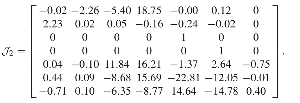
The eigenvalues of J2are computed as:0,-12.28,-0.43,-0.14±6.71i,-0.01±2.35i,in which the real parts of all the eigenvalues, except a zero eigenvalue, are negative. Therefore,point Q2is Lyapunov stable,but it is not asymptotically stable.To illustrate this point,we use the nonlinear DAEs system Eq.(8)to numerically simulate the motion of the bicycle under initial conditions neighboring the equilibrium point v*2.We perturb the equilibrium point by ˙θ(0)=±0.1 rad/s,and remain other quantities in v*2unchanged.Figure 9 shows the numerical results for the trajectories of the reference point D on the x-y plane and the evolutions of ˙φrwith respect to t.It is seen that the perturbed orbits are very close to the periodic orbit Q2at all times.Also,the perturbed angular velocity of the rear wheel approximatively converges to a constant value,neighboring but not equal to that of the circular motion Q2.The numerical investigations based on the original nonlinear DAEs system Eq.(8)support that the circular motion at point Q2is stable,but not asymptotically stable.
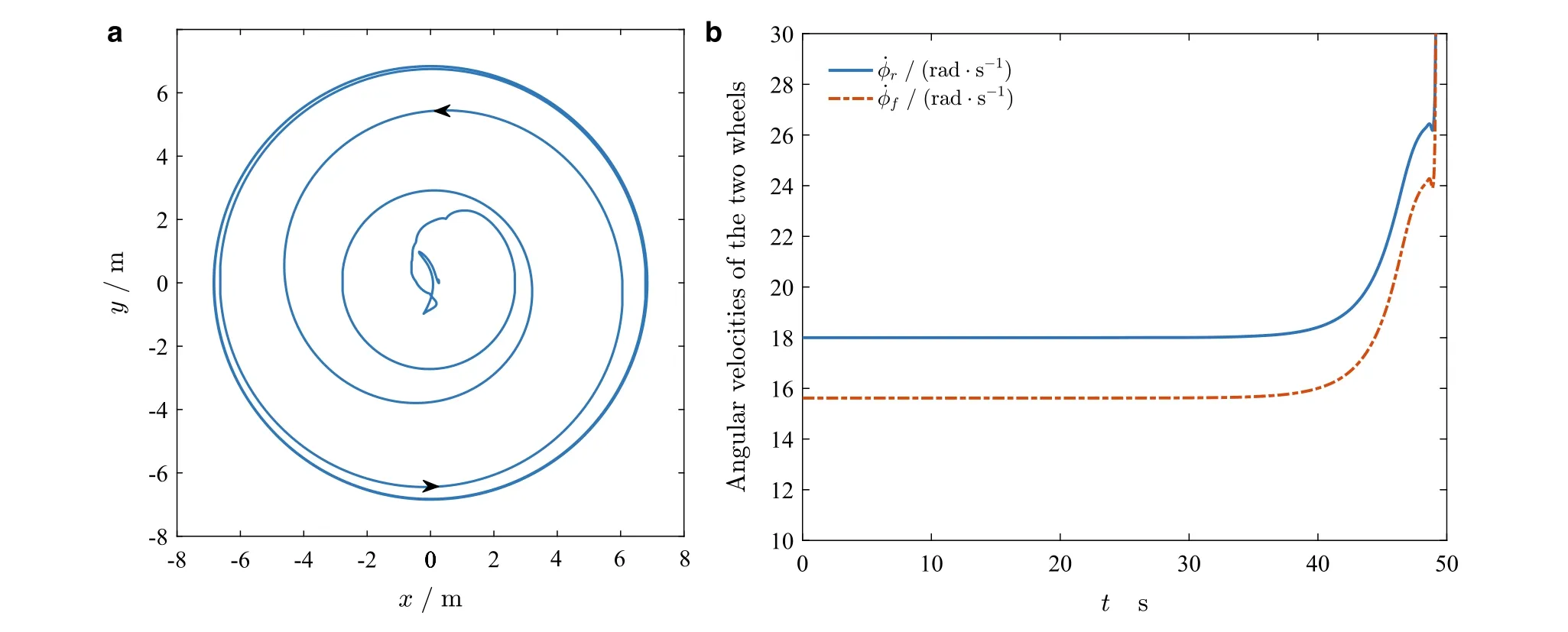
Fig.8 Simulation of an unstable periodic orbit at point Q1:a trajectory of the reference point D on the x-y plane and b the evolutions of ˙φr and ˙φ f with respect to time
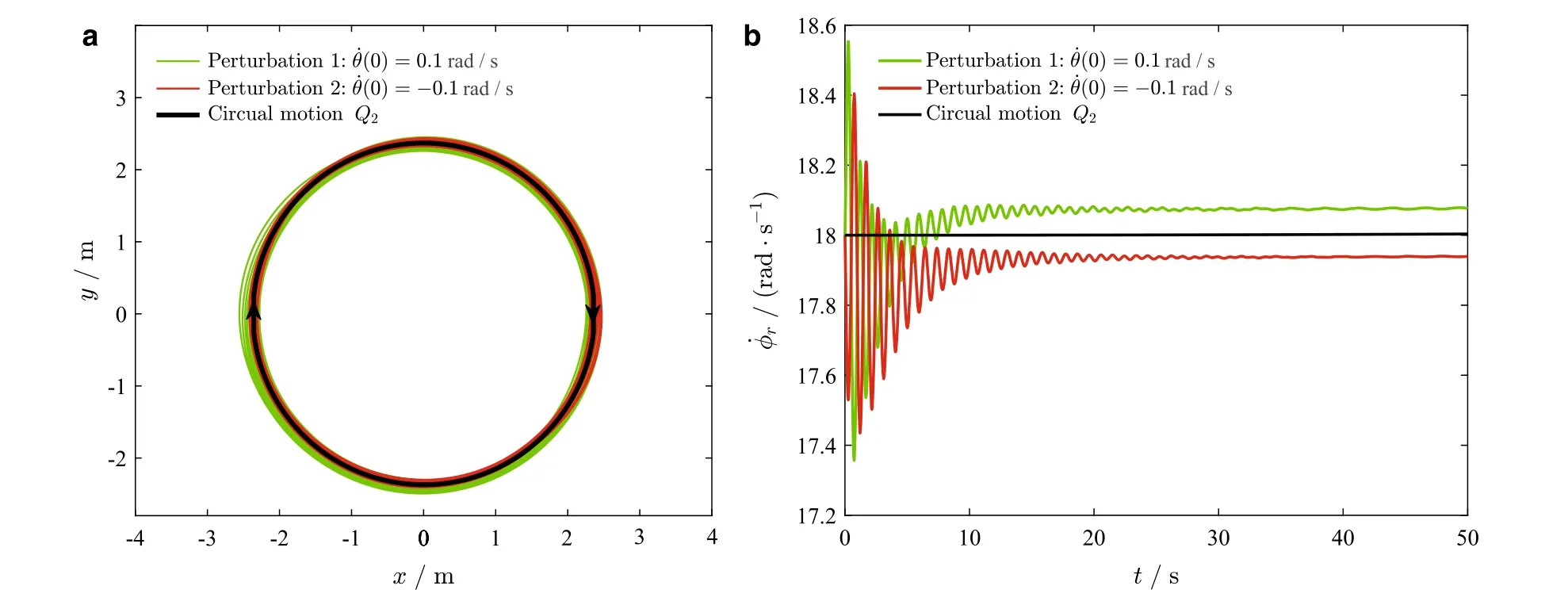
Fig.9 Numerical simulations obtained from the nonlinear DAEs system Eq.(8)under initial conditions neighboring v*2:a the trajectories of the reference point D on the x-y plane and b the evolutions ofr with respect to time
5 Conclusions
In this paper,we study the dynamics of the Whipple bicycle moving on the revolution surface.Considering the configuration dependency of the contact points and the kinematic coupling loop between the bicycle attitude and its handlebar steering,we employed the method proposed by Zhao and Liu[48],to parameterize the profiles of the ground surface and the wheel edges,to establish the contact equations between the contact parameters and the generalized coordinates,then to derive the geometric constraint equations involved in the contact points. Under the condition that no slippage exists between the wheels and the ground, together with the contact equations, four nonholonomic constraint equations are derived symbolically. We then apply the Lagrangian equations of the first type to establish the nonlinear DAEs,leaving nine coupled differential equations, six contact equations,two holonomic constraint equations and four nonholonomic constraint equations.
Noting that the variables of the DAEs system in the circular motion should be either constant or vary periodically,we introduce a rotation transformation to transfer the original DAEs system into a new one whose equilibrium point is responsible for the circular motion. Using the geometric and physical parameters of the Whipple bicycle, we apply this new DAEs system to numerically solve the solutions of the circular motion for the bicycle moving on the revolution surface.Five cases of the ground with different surface parameters are numerically investigated.Similar to the case of the horizontal ground,the circular motions on the revolution surface are not isolated,but in the form of one-parameter solution families.Four solution families still exist,and there are always one static equilibrium state(ωr= ωf= 0)and one pivoting motion(ωr= 0,.The third and the fourth families can always be merged into a combined family through the points with pivoting motion.Nevertheless,when the surface parameter α is large enough, the first, the third and the fourth solution families are merged into a combined family.
In order to analyze the Lyapunov stability of the circular motion,we first directly linearize the new DAEs system in which the time-dependent variables are removed by the rotation transformation. A reduced linearized system consisting of 7 first-order ordinary differential equations can then be established, in which the dependent coordinates are removed according to the linearized constrained equations and the symmetries arising from the cyclic coordinates.Finally,we compute the eigenvalues of the Jacobian matrix of the reduced linearized system at the corresponding equilibrium point to characterize the Lyapunov stability.We find that,when the curvature of the ground is very small,there are small sections of stable circular motions in the second and the fourth solution families. The stable region shrinks with the increase of curvature of the ground surface.When α ≥1/20,no stable region exists in the four solution families.We also present the numerical results obtained from the original nonlinear DAEs system,and show that a stable circular motion is not asymptotically stable.
In summary,we provide a comprehensive analysis of the dynamics and stability of the Whipple bicycle moving on the rotating surface.Our results help to better understand bicycle dynamics and other mechanical systems that are subject to complex constraints.
AcknowledgementsThis work was performed under the support of the National Natural Science Foundation of China(Grants 11932001 and 11702002).
杂志排行
Acta Mechanica Sinica的其它文章
- Geometric and material nonlinearities of sandwich beams under static loads
- Coupled thermoelastic theory and associated variational principles based on decomposition of internal energy
- Transient growth in turbulent particle-laden channel flow
- Experimental and theoretical investigation of the failure behavior of a reinforced concrete target under high-energy penetration
- Revealing the high-frequency attenuation mechanism of polyurea-matrix composites
- Efficient algorithm for 3D bimodulus structures
