Parametric identification of time-varying systems from free vibration using intrinsic chirp component decomposition
2020-05-06ShaWeiShiqianChenXingjianDongZhikePengWenmingZhang
Sha Wei · Shiqian Chen · Xingjian Dong · Zhike Peng · Wenming Zhang
Abstract Time-varying systems are applied extensively in practical applications, and their related parameter identification techniques are of great significance for structural health monitoring of time-varying systems. To improve the identification accuracy for time-varying systems, this study puts forward a novel parameter identification approach in the time-frequency domain using intrinsic chirp component decomposition (ICCD). ICCD is a powerful tool for signal decomposition and parameter extraction, with good signal reconstruction capability in a high-noise environment. To maintain good identification effects for the time-varying system in a noisy environment, the proposed method introduces a redundant Fourier model for the nonstationary signal, including instantaneous frequency (IF) and instantaneous amplitude (IA). The accuracy and effectiveness of the proposed approach are demonstrated by a single-degree-of-freedom system with three types of time-varying parameters, as well as an example of a multi-degree-of-freedom system. The effects of different levels of measured noise on the identified results are also discussed in detail. Numerical results show that the proposed method is very effective in tracking the smooth, periodical, and non-smooth variations of time-varying systems over the entire identification time period even when the response signal is contaminated by intense noise.
Keywords System identification · Time-varying system · Time-frequency domain · Intrinsic chirp component decomposition
1 Introduction
Dynamic systems described by linear ordinary differential or difference equations with time-dependent coefficients are often referred to as time-varying (TV) systems. This type of system has important theoretical and practical significance for its wide application in engineering structures, such as variable-speed rotating machinery [1], deployable structures in aerospace [2], and traffic-excited bridges [3]. A critical issue associated with TV systems is the problem of parameter identification, which is aimed at evaluating the instantaneous dynamic parameters of the system via the input-output data or output vibration data. These dynamic parameters, including the instantaneous natural frequencies and damping ratios, usually contain much important information about its health condition, and provide valuable guidance for structural health monitoring of TV systems [4, 5].
Over the past few decades, various identification approaches have been proposed in time or frequency domains. Frequency-domain methods [6] are widely accepted for their simplicity. However, they cannot accurately estimate the response spectrum, leading to the loss of accuracy for parameter identification. Conversely, timedomain algorithms, such as time-series approaches [7], datadriven model-based methods [8, 9], state-space system identification methods [10, 11], and the subspace algorithm [12, 13], result in fewer errors, since they do not need to estimate the spectra of the measured responses. Additionally, they are naturally convenient for parameter estimation, because methods in the time domain identify parameters relating to time. However, time-domain approaches are more sensitive to noise contamination and the order of the parametric model than are frequency-domain methods. For this reason, a variety of criteria and methods are proposed for order selection of parametric models. However, order selection results in complex procedures and high computational cost.
With the development of signal processing theory, various time-frequency analysis-based identification approaches have been proposed. The main strength of time-frequency analysis is that it can describe the trend in signal spectrum changes with time. In their study, Ghanem and Romeo [14] adopted wavelet transform theory to identify the parameters of TV systems, which transformed the dynamic equations into a wavelet expanded form by the wavelet-Galerkin method, and estimated the dynamic parameters by solving the expanded equations. In their report, Yang et al. [15] employed the parametric time-frequency transform with spline kernel to identify systems with linear and nonlinear time-varying characteristics, while Shan et al. [16] used the continuous wavelet transform to deal with the identification problem of TV systems. Studies by Dziedziech et al. [17] and Staszewski and Wallace [18] identified modal parameters using the wavelet-based frequency response function. A work by Roshan-Ghias et al. [19] employed the smoothed pseudo-Wigner-Ville distribution (SPWVD) to obtain the analytic form of single-degree-of freedom (single-DOF) mode and estimate the modal parameters by tracking the ridge in the time-frequency plane. These methods are non-parametric and are similar to the peak-picking approach. Thus, they have the usability of frequency-domain methods, but also their inherent inaccuracy.
Various efforts have also been devoted to developing Hilbert transform (HT)- or Hilbert-Huang transform (HHT)-based methods, as the HT also has the ability to decompose the signal to capture time-localized features such as the instantaneous frequency (IF) at a time instance. For a multi-degree-of-freedom (multi-DOF) system, Xu et al. [20] decomposed the responses into a series of single modes by the Gabor expansion and estimated the model parameters of those single modes using the HT. A new method was proposed by Kim and Chen [21] using a filtering algorithm based on wavelet packet decomposition to separate close modes, while Shi and Law [22] separated the response using empirical mode decomposition (EMD) via free vibration data. HHT-based identification algorithms have been successfully applied in some engineering structures [23]. However, the first stage, the EMD, suffers from border distortion and a spurious intrinsic mode component. In addition, HT- or HHT-based methods are sensitive to noise contamination.
This study proposes a novel parameter estimation approach in the time-frequency domain for improving the parameter identification accuracy of TV structures. The identification procedure is based on intrinsic chirp component decomposition (ICCD) [24], which can accurately determine the dynamic parameters of the TV system and has good estimation ability in high-noise environments. The identification algorithm procedure separates the responses into a series of single components, representing the information of single-DOF TV systems, and at the same time estimates the IFs and instantaneous amplitudes (IAs) of the signal. The dynamic parameters are then identified by those IFs and IAs.
The following section presents the problem description for parameter identification of time-varying systems, after which the basic theory of ICCD is introduced. In Sect. 3, the identification algorithm of time-varying systems with free vibration data is presented. Single-DOF and multi-DOF systems with three types of time-varying features are given in Sect. 4 to demonstrate the effectiveness and accuracy of the proposed approach. Finally, conclusions are drawn in Sect. 5.
2 Problem description
For an n-DOF time-varying system, its equation of free vibration can be expressed as

where y(t) denotes an n-DOF displacement vector. M(t), C(t), and K(t) represent the time-varying mass, damping, and stiffness matrices, respectively. For the slowly varying system, the time-varying multi-DOF system can be considered a finite number of time-invariant systems at time intervalIn a slowly varying system, the system parameters change only slightly within a period of vibration. For the time intervalEq. (1) can be expressed as

where Mi, Ci, and Kiare the time-invariant mass, damping, and stiffness of the system at time intervalThe initial conditionsandare determined by the response at the previous time interval
Using modal analysis, Eq. (2) can be decomposed into a set of single-DOF systems, i.e.,

where qidenotes the displacement response, and the upper dot designates a derivative with respect to time t. fniand ξiare the modal frequency and damping ratio of the ith mode, respectively. Based on the superposition principle, the ith component of the displacement response can be expressed as

where yij(t) is the jth intrinsic chirp component (ICC) extracted for the ith element, corresponding to the ith DOF, of the displacement vector. Actually, yij(t) represents the jth mode component of the response. Therefore, the natural frequency and damping ratio of each mode can be identified by
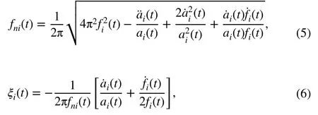
in which fi(t) is the IF of the ith mode, anddenotes its first derivative. ai(t) is the IA of the ith mode, andandare its first and second derivatives, respectively. Their detailed derivations are given in Sect. 4.1.
Equations (5) and (6) imply that the modal parameters, i.e. the natural frequency and the damping ratio, are closely related to the IF and the IA of the response signal and their derivatives. Additionally, as the derivations of IFs and IAs are usually calculated by the finite difference method, inaccurate IFs and IAs may lead to error propagation and amplification of parameter identification. Therefore, the accuracy of the extracted IFs and IAs is of great importance to the identification of time-varying systems. In addition, noise interference and response attenuation will result in large errors in signal extraction and unreliable results.
As stated in the introduction, many different methods have been effectively applied for parameter identification of time-varying systems, including frequency-domain, timedomain, non-parametric time-frequency analysis-based, and HHT-based methods. However, because of inaccurate estimation of the response spectrum, the widely accepted frequency-domain methods may fail to deal with such problems for multi-DOF systems. Non-parametric time-frequency analysis-based methods possess the inherent advantages of frequency-domain techniques but also their inaccuracy. For the HHT-based method, its weak anti-noise ability results in failure to identify TV systems in high-noise environments. Time-domain methods can effectively identify TV systems, without the need to estimate the measured response spectra. Nevertheless, they are sensitive to the order selection of parametric models, and the order selection procedure is complicated and incurs significant computational cost. Timedomain methods are also sensitive to noise contamination.
This study proposes a novel identification approach based on ICCD, which exhibits a strong capacity for signal decomposition and parameter extraction, especially in the case of intense noise contamination. A detailed description of the ICCD-based identification approach will be given in the following section.
3 Theoretical basis of ICCD
ICCD is known to provide signal-dependent analysis for nonstationary signals [24]. The most attractive features of this approach are its ability to greatly improve the accuracy of signal decomposition and parameter extraction. It also exhibits good estimation ability in a high-noise environment. Applications of ICCD include signal modeling, IF extraction, and IA extraction. Using a Fourier series, a signal is first modeled by redundant Fourier models, as are the IF and the IA. After that, the IF is extracted by the general parameterized time-frequency transform (GPTFT), which is an effective algorithm for IF extraction. By using the information obtained for the IFs, IAs are obtained using the regularization least-squares method. The procedure is presented in detail as follows.
3.1 Signal modeling
Considering the unavoidable noise contamination, a general amplitude-modulated-frequency-modulated (AM-FM) signal can be modeled as

where y(t) is the system output signal and ε(t) is the noise term, which is simulated by Gaussian white noise with zero mean in this study.
The general signal z(t) usually contains multiple components which can be modeled as follows

in which

where K is the number of ICCs which are the basis function of the ICCD. N is the number of samples. fm(t), am(t), and φm0are the IF, the IA, and the initial phase of the mth ICC, respectively.
Equation (2) can also be described as

where Am(t) = am(t)cosφm0and Bm(t) = -am(t)sinφm0. Based on the redundant Fourier model, the IA and IF of each ICC can be represented by in which P and Q are the order of IA and IF respectively. F0= Fs/(2N) and Fsdenotes the sampling frequency.
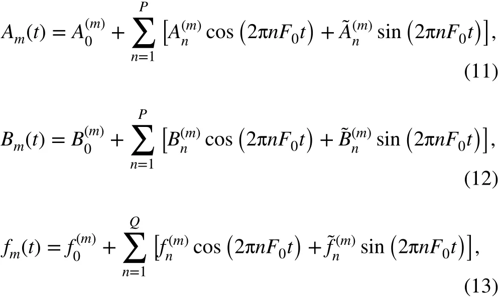
As the models of the IF and the IA have been established, the main computational process involves estimating the coef}-ficients of the IF and the IA, i.e.andThe signal can then be reconstructed through the redundant Fourier model.
3.2 Instantaneous frequency extraction
The IF parameters are first estimated using the GPTFT [25], which is a new time-frequency (TF) transform for a signal using the transformation operators and the Gaussian window. The GPTFT can generate well-concentrated TF distributions even when the signal is contaminated by intense noise, mainly because the signal can be transformed into a stationary signal in each Gaussian window by selecting proper transformation parameters.
For the mth ICC in Eq. (2), the analytic signal Ym(t) can be defined by the Hilbert transform

in which the phase model can be obtained by integrating Eq. (6)

The parametric TF transform of the mth ICC can described by

where ΦDβ(τ) represents the demodulation operator and is used to reduce the IF variation of the analytic signal Ym(t).denotes the compensation operator which is employed to compensate the estimated error caused bydesignates the Gaussian window with length σ

Fig. 1 Simulated signal with 20 dB noise in the a time and b time-frequency domains
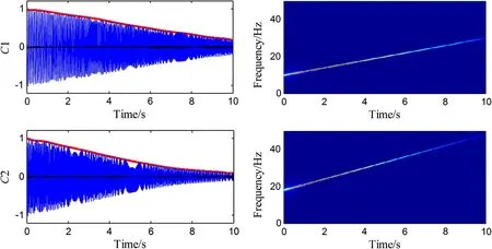
Fig. 2 Separated components by ICCD for the simulated signal in the time and time-frequency domains (red and black lines respectively denote the extracted IAs and reconstruction errors)
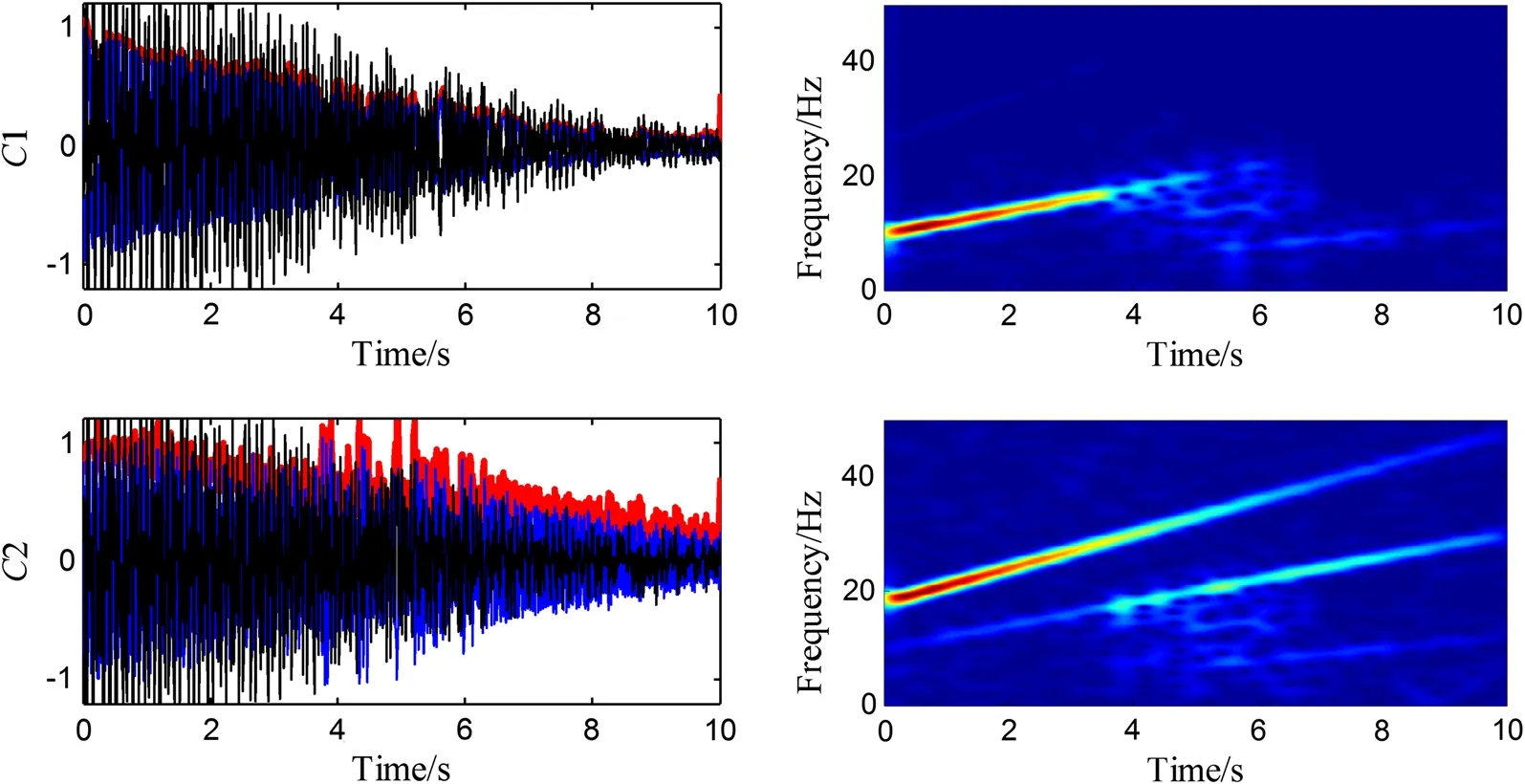
Fig. 3 Separated components by the HHT for the simulated signal in the time and time-frequency domains (red and black lines respectively denote the extracted IAs and reconstruction errors)
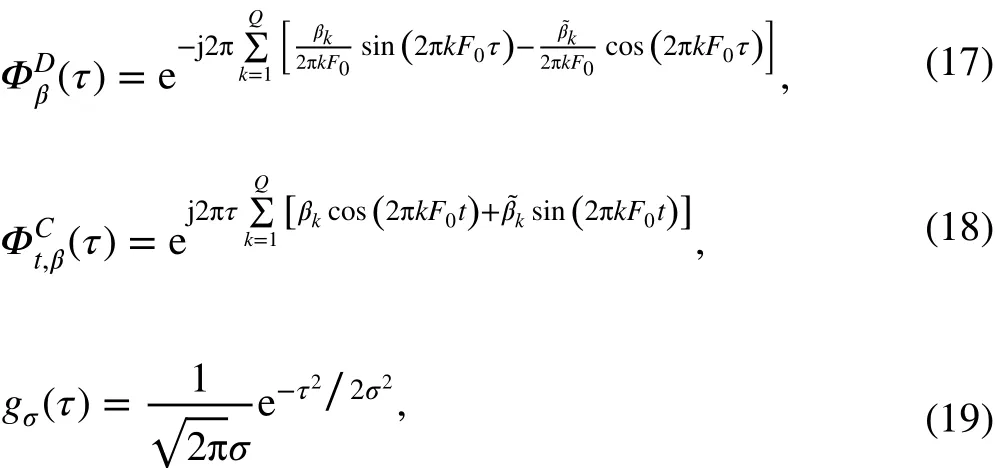
The IF of the signal ym(t) is equal to the IF value of TF(t,f,β) at time τ = t. For obtaining the parametric TF transform of the mth ICC, the estimation of the transformation parameter β is the critical step. It is obtained by the TF ridge extraction through the Viterbi algorithm. For greater detail about the IF extraction procedure, one can refer to Ref. [24].
3.3 Instantaneous amplitude extraction
As the IFs of the signal have been estimated, the IA parameters can be calculated by solving an l2-regularized leastsquares problem, which can be expressed as
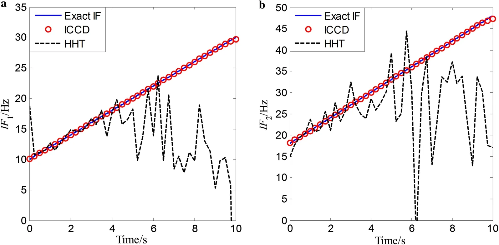
Fig. 4 Extracted IF components using the HHT and ICCD under SNR = 20 dB
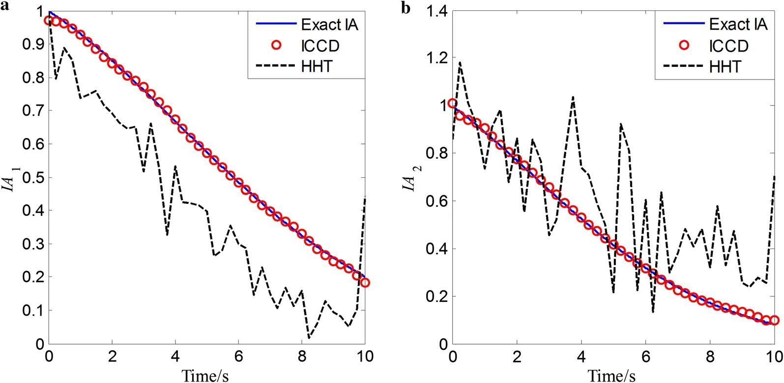
Fig. 5 Extracted IA components using the HHT and ICCD under SNR = 20 dB

where α is the regularization parameter.in whichi.e. the unknown coefficients

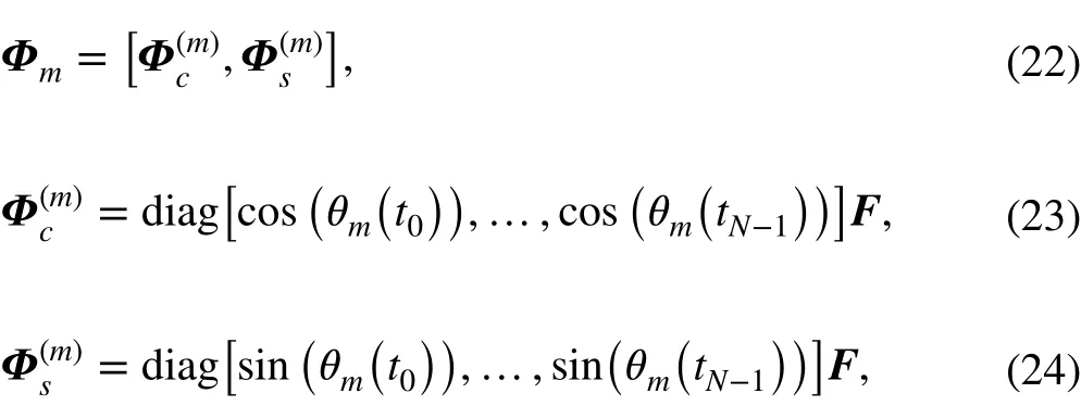

in which θm(t)=2πwhich is determined by the estimated IFThe solution of Eq. (7) can also be expressed as

where E is an identity matrix.
The IA parameters can be obtained by solving Eq. (9). The IAs of Eq. (2) can then be recovered byin which the estimated envelopesandcan be obtained by Eqs. (4) and (5).
Note that ICCD can also be regarded as a time-varying filter bank whose center frequencies are the estimated IFs, and bandwidth is expressed as

where P is the order of IA, and F0= Fs/(2N), in which Fsdenotes the sampling frequency. The bandwidth selection in ICCD is based on the definition formula.
3.4 Simulation comparison
To demonstrate the effectiveness and the anti-noise property of ICCD, a simulated signal with two time-varying components is considered, in which the signal is described by

where 0 ≤t ≤10 . Additionally, it is assumed that the simulated signal is corrupted by noise, with a signal-to-noise ratio (SNR) equal to 20 dB.
The theoretical values of the IFs (Hz) are

and the IAs are

The two methods, i.e. ICCD and the HT-based method, are respectively applied to extract the IFs and IAs of the signal. For ICCD, the sampling frequency is set as 100 Hz and the bandwidth is set to 1% of the sampling frequency. The simulated signal in the time, frequency, and time-frequency domains is given in Fig. 1. It is clear that the simulated signal is non-stationary and is contaminated by noise. The decomposition components by ICCD and the HHT are shown in Figs. 2 and 3, respectively. The two components are respectively represented by C1 and C2. The black lines denote the reconstruction errors of the components. Comparing the reconstruction errors of each component in Figs. 2 and 3, the reconstruction errors by ICCD are much smaller than those by the HHT. From the time-frequency results of the signal, one can also observe that the components separated by ICCD have better time-frequency representations (TFRs) with high energy concentration than those by the HHT. Additionally, the HHT-based method suffers from spurious intrinsic mode components and is sensitive to noise contamination. The extracted IF and IA components using the HT and ICCD are plotted in Figs. 4 and 5, respectively. It is clear that the results for ICCD are consistent with the theoretical values. However, the results for the HHT show strong fluctuations and boundary effects. Therefore, the ICCD-based method exhibits superior accuracy in reconstructing each component under a high-noise environment.
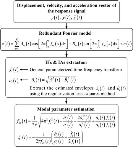
Fig. 6 Computational procedure for ICCD-based modal identification
4 Identification technique via free vibration data
4.1 Single-DOF systems
For a single-DOF time-varying system, the governing equation of motion can be expressed as

where y(t) is the displacement response, and m(t), c(t), and k(t) denote the time-varying mass, damping, and stiffness of the system, respectively. As stated in Sect. 2, the system equation can be derived as a finite number of time-invariant systems in the time intervaland expressed as

where mi, ci, and kiare the time-invariant mass, damping, and stiffness of the system at time intervalThe initial conditions are determined by the response at the previous time intervalThus, the problem of time-varying system identification becomes the identification of a finite number of time-invariant parameters at each time interval.
Suppose that the analytic signal of y(t) is expressed as

in which a(t) is the instantaneous amplitude and ψ(t) is the instantaneous phase angle. The first and second derivatives of Eq. (33) can then be expressed as

in which

where f(t) denotes the IF of the single-DOF system and ˙f(t) is the time derivative of f(t) . By substituting Eqs. (33)-(35) into Eq. (30), the identified natural frequency and damping ratio can be derived as the following explicit expressions, which are the same as shown in Refs. [21, 26]
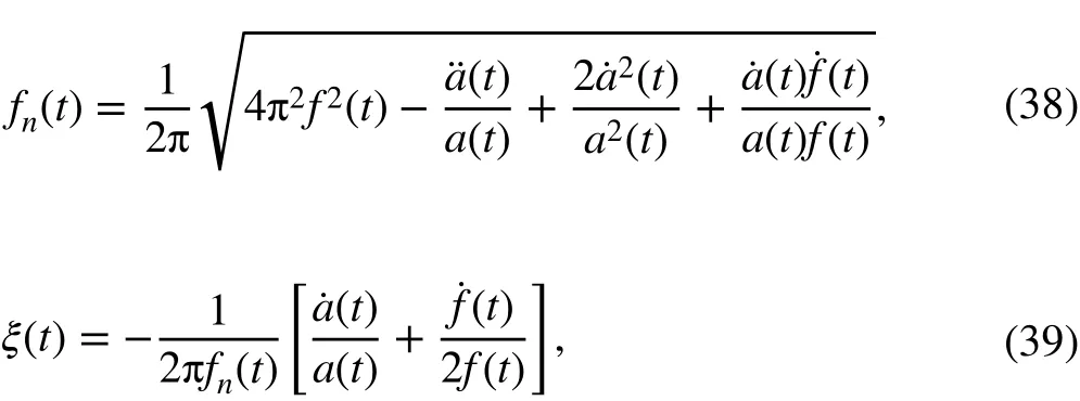
in which ˙a(t) and ¨a(t) are the first and second derivatives of the IA, respectively. Specifically, the f(t) ,and a(t) can be directly obtained with the ICCD-based approach. ˙a(t) andcan be calculated by the finite difference method.
4.2 Multi-DOF systems
As the linear time-varying structure is a general form of the linear structure which also satisfies the superposition principle, a linear time-varying multi-DOF structure can be expressed as the superposition of a set of responses of single-DOF structures. Additionally, the response of each linear time-varying structure possesses the properties representing the time-varying features of the system at some mode. From this point, by extracting each mode component from the response signal, the dynamic parameters can be estimated using the identification method described in the previous subsection. For multi-DOF TV systems, the natural frequency and damping ratio of each mode are given by Eqs. (5) and (6) in Sect. 2.
As shown in Fig. 6, the procedure for parameter identification of multi-DOF time-varying systems using ICCD can be summarized as follows.
a. Obtain the displacement, velocity, and acceleration responses of the system.
b. Decompose the measured response and extract the IFs and IAs from the single-order response components using ICCD.
c. Estimate instantaneous model parameters, such as the natural frequency and damping ratio, by Eqs. (38) and (39).
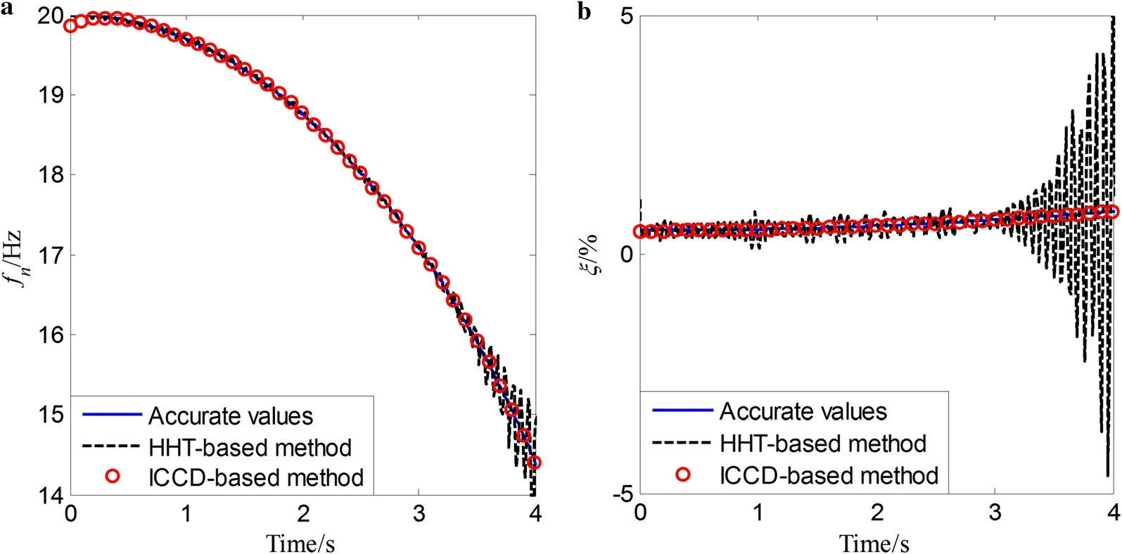
Fig. 7 Identified results for smooth variation of the time-varying single-DOF system without noise
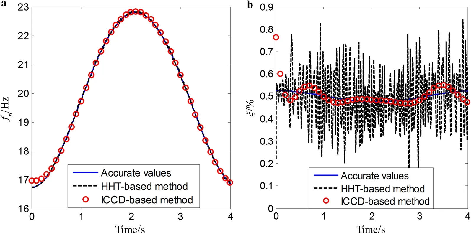
Fig. 8 Identified results for periodical variation of the time-varying single-DOF system without noise
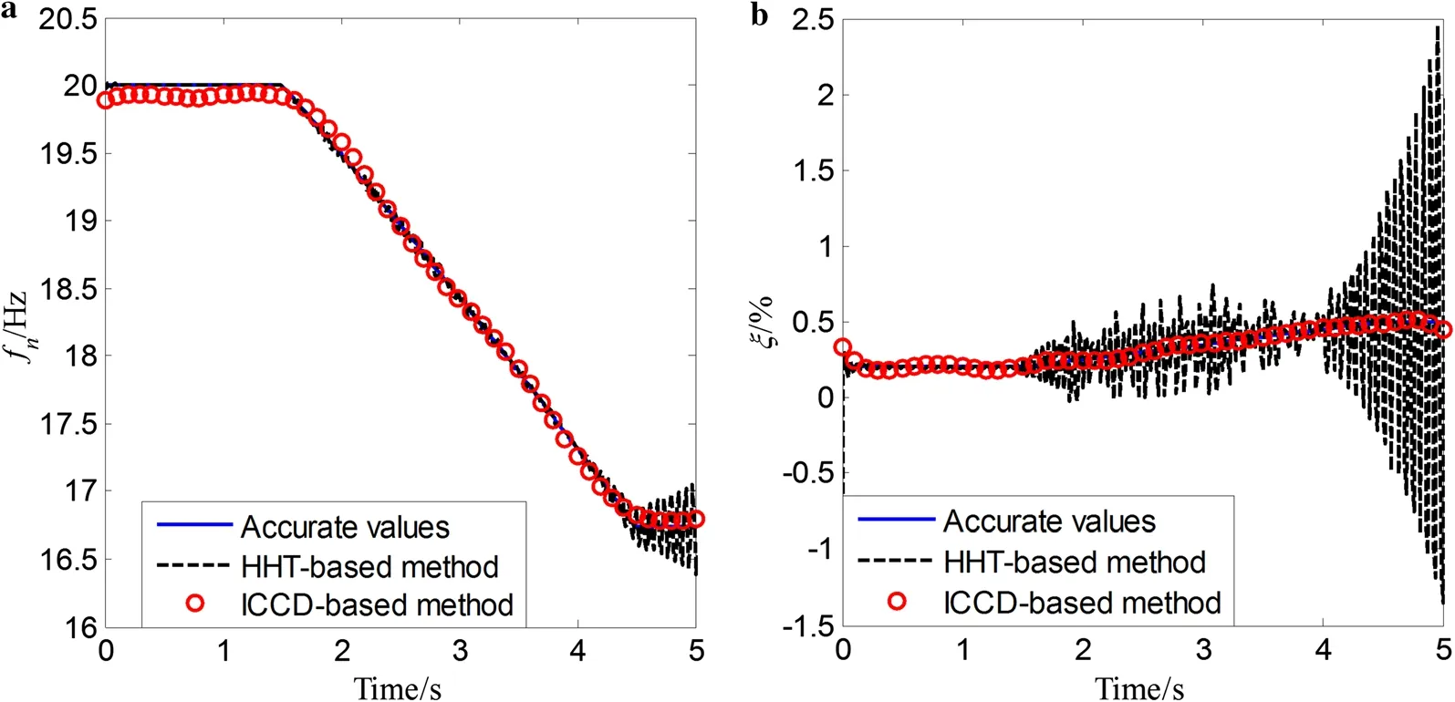
Fig. 9 Identified results for non-smooth variation of the time-varying single-DOF system without noise
Additionally, to quantitatively evaluate the accuracy of the proposed method, the mean absolute percentage error (MAPE) is introduced by
where piand ^pidenote the theoretical and identified parameters at the ith time instance. N is the total number of samples.
5 Numerical simulations
5.1 Identification of single-DOF systems
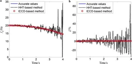
Fig. 10 Identified results for smooth variation of the time-varying single-DOF system under SNR = 20 dB
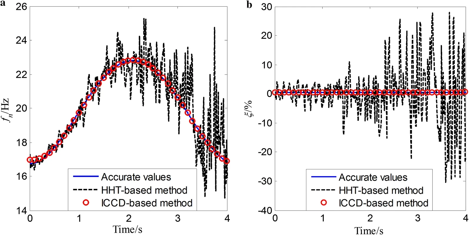
Fig. 11 Identified results for periodical variation of the time-varying single-DOF system under SNR = 20 dB
A single-DOF system with three types of time-varying stiffness and damping coefficients, i.e. the smoothly, periodically, and non-smoothly varying parameters, is considered first. The mass coefficient of the system is assumed to be known. The response signals, including displacement, velocity, and acceleration responses, are then calculated by the fourth-order Runge-Kutta method with a sampling frequency of 100 Hz. The initial displacement and velocity are set as y0=1 m and=0 ms-1. Specifically, the displacement response is used for the parameter estimation of the proposed method, and the displacement, velocity, and acceleration responses are used for that of the HHT-based method.
For smoothly time-varying systems, the damping and stiffness parameters are given as [27]


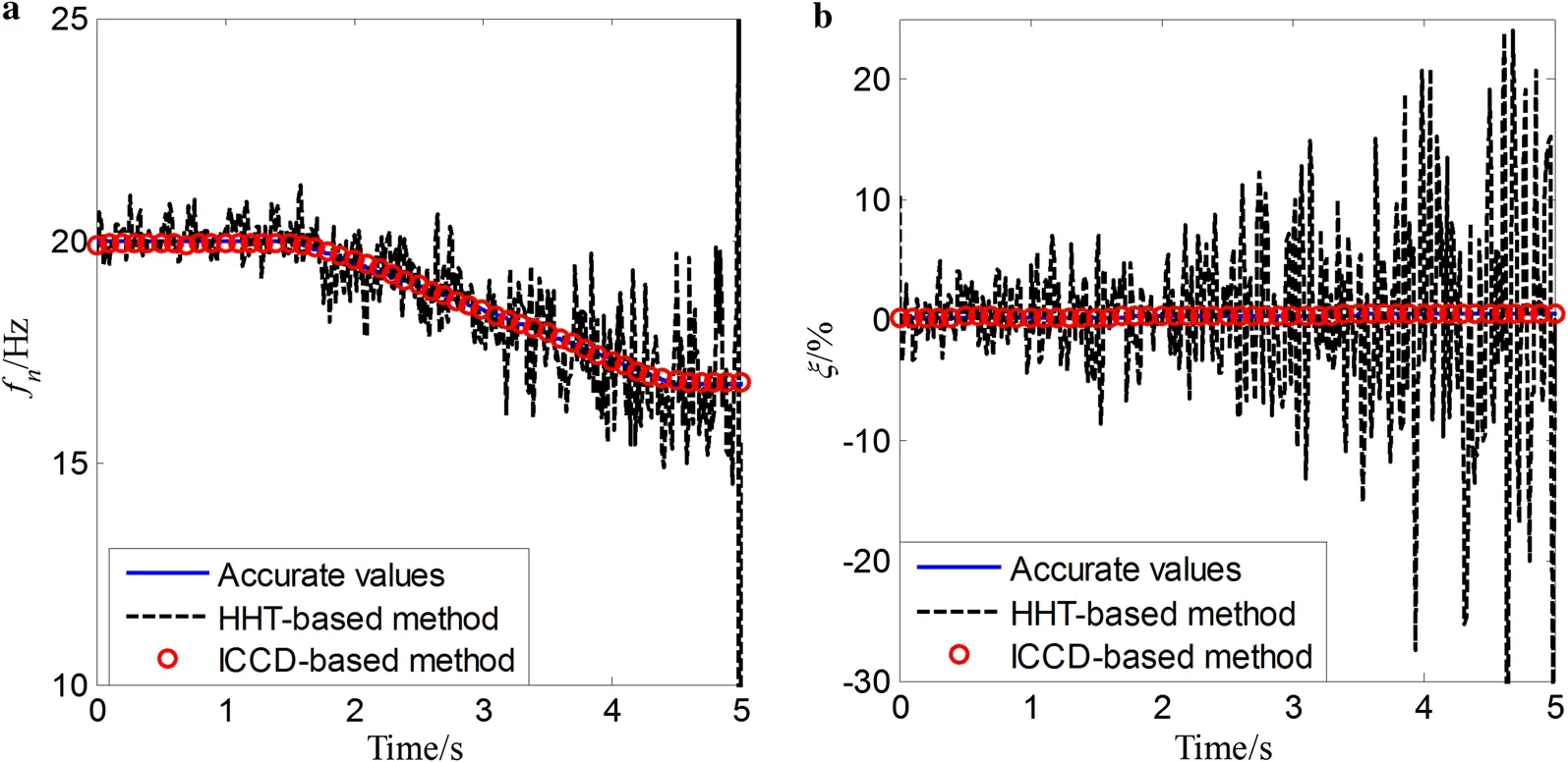
Fig. 12 Identified results for non-smooth variation of the time-varying single-DOF system under SNR = 20 dB

Table 1 MAPEs for three types of single-DOF time-varying systems with different levels of noise
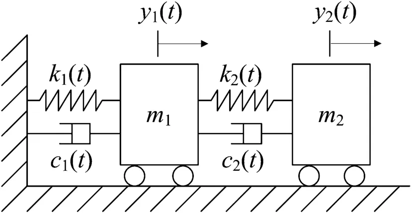
Fig. 13 Two-DOF linear time-varying system


First, the response data are not corrupted with noise. The instantaneous natural frequencies and damping ratios are estimated by the proposed identification approach and the HHT-based algorithm. For those three types of time-varying systems, comparative results of the true value, the proposed method, and the HHT-based algorithm are respectively shown in Figs. 7, 8, and 9. It can be observed that both the estimated instantaneous natural frequencies and damping ratios using the proposed identification approach are very close to the corresponding accurate values. In addition, the estimated instantaneous natural frequencies by the HHTbased method are also close to the accurate values. However, those estimated damping ratios by the HHT-based method have the ripple phenomenon that the estimated damping ratios significantly fluctuate with time. It is implied that the proposed method can provide a much better estimation for instantaneous modal parameters, including instantaneous natural frequencies and damping ratios, regardless of the measured noise.
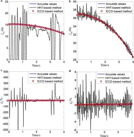
Fig. 14 Identified results for smooth variation of the time-varying two-DOF system without noise
To illustrate the effectiveness of the proposed method with measured noise, the response signal is assumed to be corrupted with zero mean Gaussian noise. The identified results for the above three types of time-varying single-DOF systems with 20 dB noise are plotted in Figs. 10, 11, and 12, respectively. The results show that, for the three single-DOF time-varying systems, the estimated results using the proposed method are all more accurate than those obtained by the HHT-based method over the whole time period, which implies that the proposed method is very effective for tracking the parametric variations of the system in a noisy environment. Additionally, a comparison of the MAPEs with different levels of noise by the proposed method is shown in Table 1. The results show that the MAPEs of the identified instantaneous natural frequencies are nearly unchanged at different levels of noise, with all the MAPEs smaller than 0.5%. Additionally, the MAPEs of the identified damping ratios increase as SNR decreases for all three types of timevarying systems, with all the MAPEs smaller than 10%. These results imply that for the time-varying single-DOF system, the proposed method is robust in a noisy environment and is not sensitive to the noise for estimation of the instantaneous natural frequencies.
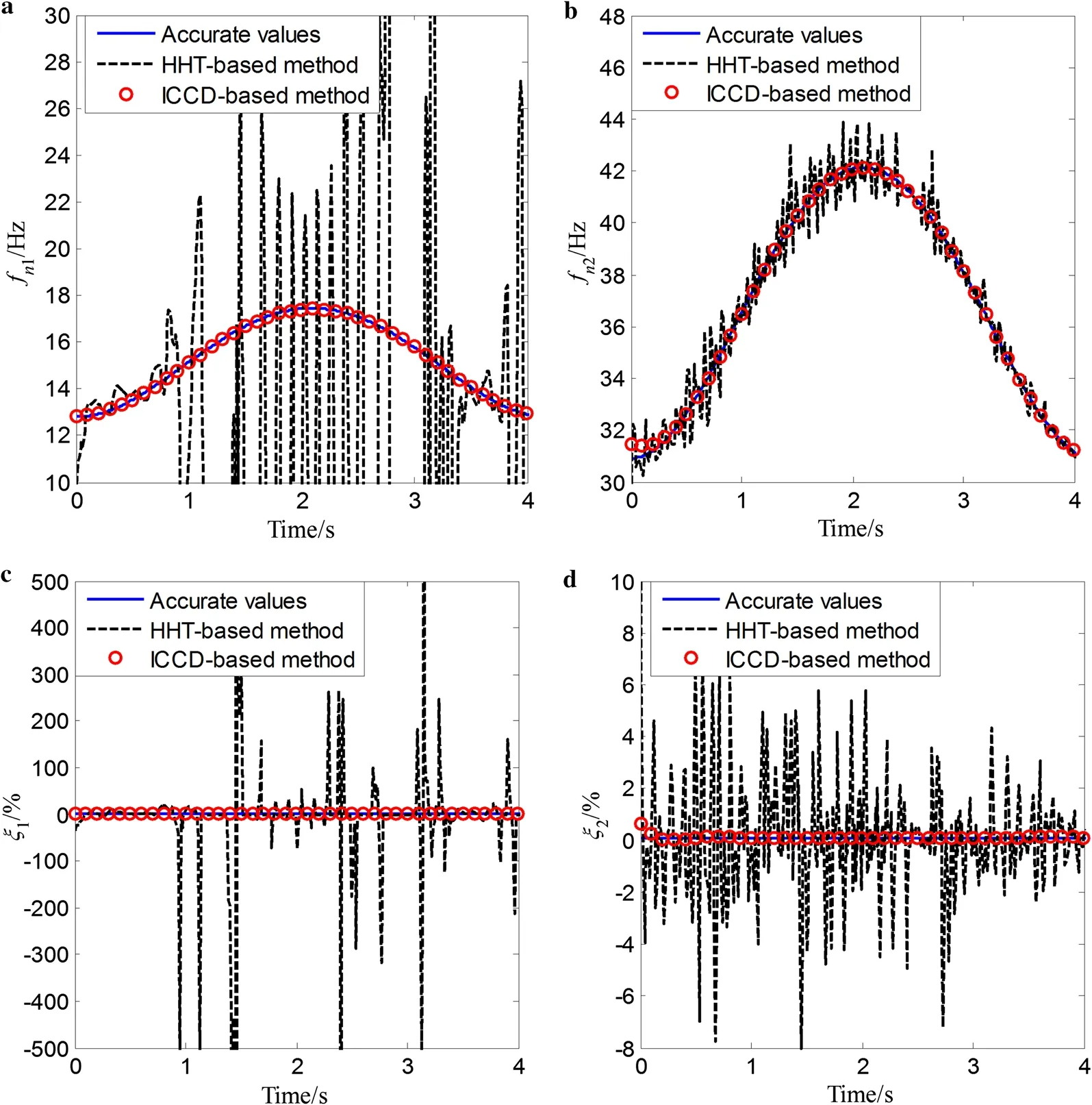
Fig. 15 Identified results for periodical variation of the time-varying two-DOF system without noise
5.2 Identification of multi-DOF systems
To demonstrate the accuracy and effectiveness of the proposed method for identification of multi-DOF systems, a two-DOF mass-spring-damping model is considered, as shown in Fig. 13, with the following parameters. The mass coeffi-cients of the system are assumed to be constant, and are set as m1=m2=1 kg, and the damping and stiffness coefficients are time-varying. The initial conditions are y0,1=1 m, y0,2=1 m,=0 ms-1, and=0 ms-1. The displacement, velocity, and acceleration responses are also calculated by the fourth-order Runge-Kutta method with a sampling frequency of 100 Hz.
The numerical examples in this subsection also include three types of time-varying systems. The stiffness and damping matrices can be derived as


Additionally, for the different types of time-varying systems, the terms r(t), ξ1(t), and ξ2(t) are different. Specifically, for smoothly time-varying systems, the various terms are given as [27]

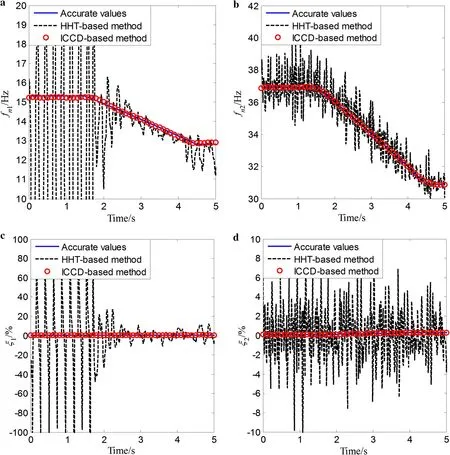
Fig. 16 Identified results for non-smooth variation of the time-varying two-DOF system without noise

in which a1= -0.03 s-2, ξ0,1= 0.5%, ξ0,2= 0.1%, b1= 0.05ξ0,1s-2, and b2= 0.08ξ0,2s-2. For periodically time-varying systems, the various terms are given as

in which p1= -0.3, q1= 0.05ξ0,1, and q2= 0.08ξ0,2, and Ω2= 1.5 rad·s-1. For non-smoothly time-varying systems, they are given as in which T is the length of the simulated time and its unit is s.
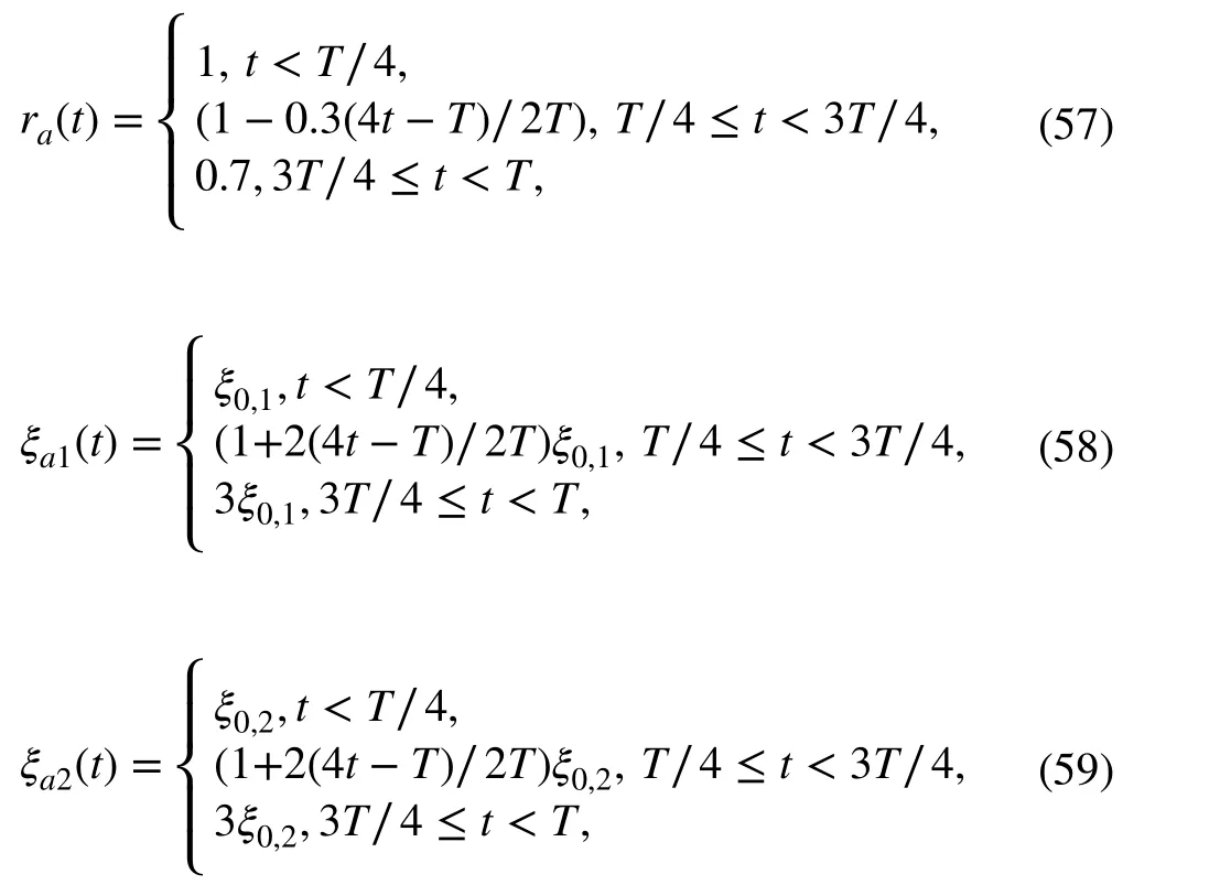
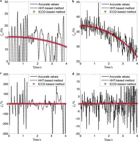
Fig. 17 Identified results for smooth variation of the time-varying two-DOF system under SNR = 20 dB
The response signals without measured noise are discussed first. The proposed identification method uses only the displacement response signal y1(t), while the HHT-based method requires the displacement, velocity, and acceleration response signal. For these three types of time-varying systems, the comparative results for identification of instantaneous natural frequencies and damping ratios are given in Figs. 14, 15, and 16, respectively. It is noted that the estimation of the instantaneous natural frequencies and damping ratios are very close to the accurate values, implying that the proposed method demonstrates good tracking behavior on those three systems. Conversely, the identified results by the HHT-based method exhibit significant fluctuations across the whole identification time period. The proposed method is thus found to demonstrate good identification ability for the time-varying multi-DOF systems without measured noise.
The identified results for the three types of time-varying multi-DOF systems with 20 dB measured noise are shown in Figs. 17, 18, and 19, respectively. The results of the proposed method, the HHT-based method, and the accurate values are all given. One can see that the results of the proposed method agree well with the accurate values. However, the results by the HHT-based approach exhibit a significant ripple phenomenon for the identification of the instantaneous natural frequencies and damping ratios. Comparisons of the MAPEs for the instantaneous natural frequencies and damping ratios with different levels of noise are listed in Tables 2, 3, and 4, respectively. It is shown that the instantaneous natural frequencies, whose MAPEs are all smaller than 0.5% under different levels of noise, are identified with very high accuracy, and the MAPEs of instantaneous damping ratios are higher when the SNR is decreased. This indicates that the proposed algorithm is very effective for tracking time-varying parameters of multi-DOF systems in a noisy environment, even for the case with non-smooth changes in the parameters.
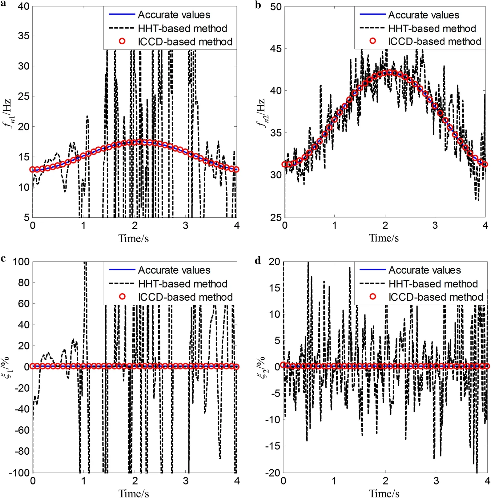
Fig. 18 Identified results for periodical variation of the time-varying two-DOF system under SNR = 20 dB
6 Conclusions
The parameter identification of time-varying systems has been addressed in this study. A procedure based on the intrinsic chirp component decomposition of the governing equations of motion is implemented to estimate the instantaneous model parameters of time-varying systems. In the proposed approach, the instantaneous frequency and amplitudes are both modeled by the redundant Fourier series, which can improve the anti-noise property of the method. The IFs and IAs of the response signal can then be directly fitted by the general parameterized time-frequency transform and the regularization least-squares method. After that, the instantaneous model parameters, including instantaneous natural frequencies and damping ratios, can be estimated at each time instant. Three kinds of time-varying parameters are used to investigate the effectiveness and accuracy of the proposed identification algorithm. The results show that the proposed approach is more accurate for tracking the parametric variations of the system, including the smoothly, periodically, and non-smoothly time-varying systems, than the HHT-based method in a noisy environment. Additionally, the proposed method is not sensitive to the noise for estimation of the instantaneous natural frequencies, and the identification errors of instantaneous damping ratios become larger when the signal-to-noise ratio of the response signal is increased. Future work to be considered involves the application of the proposed time-frequency approach for time-varying systems from forced vibration.
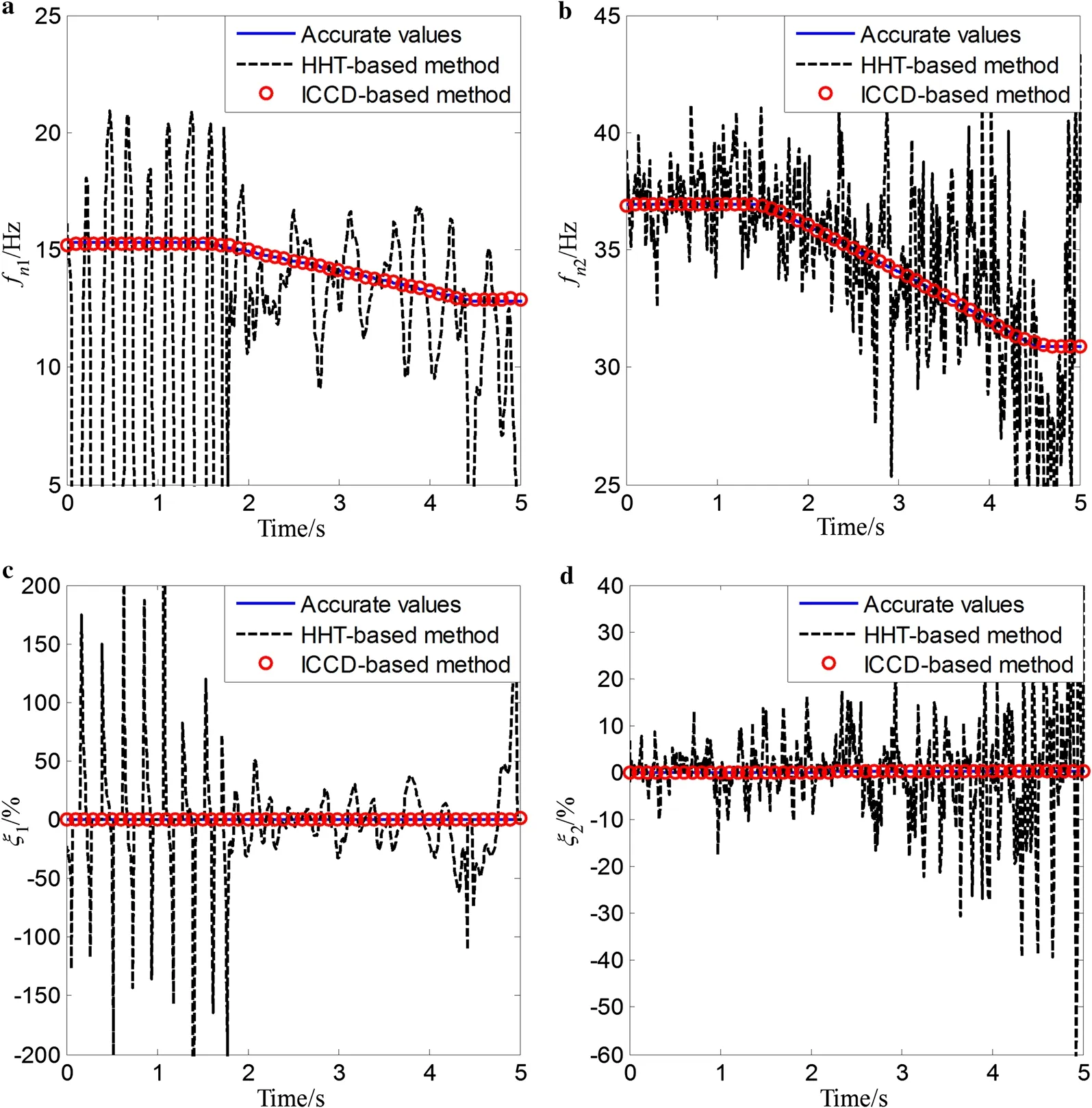
Fig. 19 Identified results for non-smooth variation of the time-varying two-DOF system under SNR = 20 dB

Table 2 MAPEs for smooth variation of multi-DOF time-varying systems with different levels of noise

Table 3 MAPEs for periodical variation of multi-DOF time-varying systems with different levels of noise

Table 4 MAPEs for non-smooth variation of multi-DOF time-varying systems with different levels of noise
AcknowledgementsThe research work was supported by the National Natural Science Foundation of China (Grants 11702170, 11632011, and 11802279) and the China Postdoctoral Science Foundation (Grant 2016M601585).
杂志排行
Acta Mechanica Sinica的其它文章
- Geometric and material nonlinearities of sandwich beams under static loads
- Coupled thermoelastic theory and associated variational principles based on decomposition of internal energy
- Transient growth in turbulent particle-laden channel flow
- Experimental and theoretical investigation of the failure behavior of a reinforced concrete target under high-energy penetration
- Revealing the high-frequency attenuation mechanism of polyurea-matrix composites
- Efficient algorithm for 3D bimodulus structures
