Generalized stiffness and effective mass coefficients for power-law Euler-Bernoulli beams
2020-05-06PiotrSkrzypaczDauletNurakhmetovDongmingWei
Piotr Skrzypacz·Daulet Nurakhmetov·Dongming Wei
Abstract We extend the well-known concept and results for lumped parameters used in the spring-like models for linear materials to Hollomon’s power-law materials.We provide the generalized stiffness and effective mass coefficients for the power-law Euler-Bernoulli beams under standard geometric and load conditions.In particular,our mass-spring lumped parameter models reduce to the classical models when Hollomon’s law reduces to Hooke’s law.Since there are no known solutions to the dynamic power-law beam equations,solutions to our mass lumped models are compared to the low-order Galerkin approximations in the case of cantilever beams with circular and rectangular cross-sections.
Keywords Power-law Euler-Bernoulli beams·Lumped parameter models·Generalized stiffness coefficient·Effective mass coefficient
1 Introduction
In design of mechanical systems, it is essential to estimate the natural frequencies and amplitudes of the structural elements. To this end, lumped-parameter spring-mass models have been successfully established and widely used for materials which behave linearly within the geometric and load conditions as defined by Hooke’s law.In this paper,we consider selected loading and boundary conditions for beams made of materials which can be characterized by Hollomon’s constitutive equation

where σ,ε,K and n ∈(0,1)denote the stress,strain,strength coefficient,and strain-hardening(or work-hardening)exponent,respectively.The constitutive Eq.(1)can be considered as generalization of Hooke’s law which is stated for linear elastic materials(n = 1).Materials modeled by Eq.(1)are also called work-hardening materials,sometimes referred to as Ludwick materials[1,2].The power-law constitutive equation(1)is a well-known empirical relation that represents the experimental non-linear stress-strain relation for annealed metals, such as annealed copper and N.P.8 aluminum alloy[3,4]. The values of K and n for some common annealed metals can be found in undergraduate textbooks and in the engineering literature,e.g.,[5-7].
The main goal of the paper is to present an applicable method for studying dynamic behaviour of vibrating powerlaw beams whose deflection u(t,x)at the axial position 0 <x <ℓ and at the time t >0 is described by the following non-linear partial differential equation[2,8],

which is complemented by the appropriate boundary and initial conditions.In the above equation,ϱ denotes the density of material, A is the cross-sectional area,and Inis the moment of inertia of the cross-sectional area of the beam relative to the neutral axis.
In the case of the cantilever power-law beam whose one end is fixed and another one free, the boundary conditions are specified as
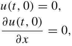

and the initial conditions can be described by the shape of the beam when the external force F >0 acts at the tip at t =0 and it will be immediately released
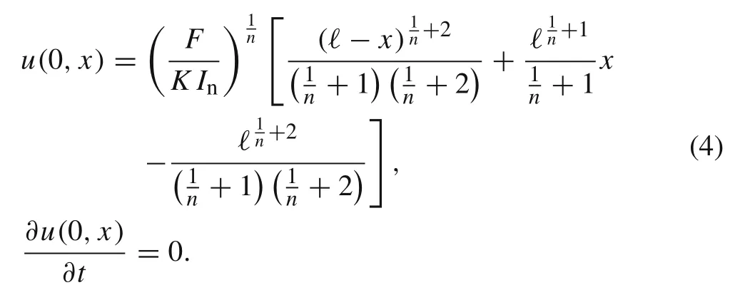
The initial deflection u(0,x)=v(x)results from the solution of the static beam problem

subject to the boundary conditions
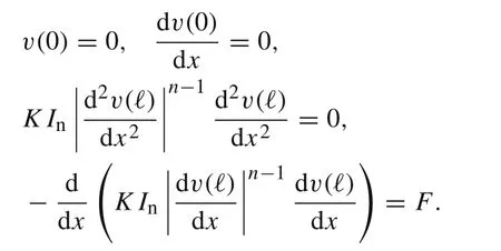
The static problem Eq.(5)will be discussed in details in Sect.2. In general, the exact solution to initial/boundary value problem for the dynamic power-law beam Eq.(2)is an open problem.
The power-law materials and the power-law beam equations are widely introduced to undergraduate engineering students at the sophomore level. More sophisticated beam equations that model the power-law materials exist but are less accessible to students,see Refs.[9,10].However,to our knowledge, there are very few mathematical models in the literature which provide simple benchmarks with analytic or numerical solutions. Lewis and Monasa [11] numerically solved the static equation for the large deflections of cantilever beams made of materials of the Ludwick type subjected to one vertical concentrated force at the free end,and obtained a closed-form solution when an end moment is applied instead[12].Adding a uniformly distributed load,Lee[13]was able to obtain numerically the slopes and deflections at the free end. A comprehensive list of publications regarding various configurations of nonlinearly elastic planar beams can be found in Ref.[14]where authors included a useful comparison between Hookes, Ludwicks and generalized Ludwick s models, i.e. the models which can be relatively easily and effectively used in engineering practice.The large deflections of slender, non-prismatic cantilever beams subjected to a combined loading which consists of a non-uniformly distributed continuous load and a concentrated load at the free end of the beam were studied in Ref.[15] where the material of the cantilever was assumed to obey the generalized Ludwick constitutive law.The authors compared the numerical solutions with results obtained from a laboratory experiment. Recently, Liu et al. [16] proposed a theoretical approach to describe the large deflection of curved beams made of the Ludwick type material,wherein the geometric nonlinearity and material nonlinearity are both incorporated. He established the geometric equations and governing equations through the piecewise-integration method, and presented the numerical solutions using the shooting method. In Ref. [17], computations of the elastica of non-prismatic and nonlinear elastic cantilever beams under combined loading have been presented for three beam materials:steel,the N.P.8 aluminum alloy,and annealed copper. The tested beams had solid rectangular cross-sections with widths and heights varying linearly along the beam axes under uniform loading,tip point loading,and tip couple loading individually or in combination.The derived ordinary differential equations that govern the elastica of such beams were solved numerically.In[18],the mechanical behavior of a non-linear functionally graded material(FGM)cantilever beam subjected to the end force was investigated by using large and small deformation theories. Modern applications of the work-hardening metals can be found from bumper beams in the automobile industry [19] to micro-grippers in bio-engineering[20].
In our lumped parameter approach for the non-linear materials,the oscillations of the power-law beam u(t,xp)at the particular point xpwill be approximated by the oscillations of the one-degree-of-freedom spring-like model as follows[21-23]

where knand meff(n) denote the stiffness coefficient and the effective beam mass,respectively,and X(t) ≈u(t,xp).We notice that one-degree-of-freedom spring-like models are widely used in analysis of dynamics of beams made of non-linear materials [21], especially in analysis of microelectro-mechanical systems[24-26].The differential Eq.(6)is a simple consequence of the second Newton law for the point of mass meff(n) accelerated by the restoring force-kn|X|n-1X.The effective mass meff(n) = μeff(n)m must be calculated as an appropriate portion of the total beam mass m and it refers to the fact that in the case of a cantilever beam,the mass near the support almost does not contribute to the motion.This observation can be also done for other flexible structures of distributed mass where not all of their portions may participate in a particular mode of motion nor do they necessarily participate in the same proportion,cf.Ref.[23].
In the case of beams made of linear materials, the corresponding stiffness coefficient for the spring-like model is specified as
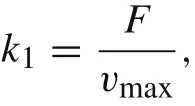
where F denotes the external load and vmaxstands for the maximal deflection of the beam at the particular point.In the case of beams made of power-law material, we define the corresponding stiffness coefficient as

Our concept of stiffness coefficients for beams made of power-law materials is a generalization of the well-known mass lumped approach for beams made of linear materials(n =1)which obey Hooke’s law.
We will use the so-called Rayleigh method to determine the effective mass meff=meff(n)for the mass lumped model of various types of beams.For this,let the kinetic energy of the cantilever beam be written in the form of


In the method of Rayleigh[23],it is assumed that

Then, Eq. (9) is differentiated with respect to time while keeping x fixed

Next,the kinetic energy of the whole beam of length ℓ can be calculated as


The paper is organized as follows. In Sect. 2, we calculate the generalized stiffness coefficients for various types of power-law beams using our concept of stiffness coefficients for beams made of power-law materials.In Sect.3,we show the way how to obtain the effective mass coefficient for the case of cantilever beam made of power-law materials using the Rayleigh principle.In Sect.4,we present numerical results for the vibrating cantilever beam,and in Sect.5,we compare our mass lumped approach with the low-order Galerkin method.Finally,we draw the conclusions in Sect.6.
2 Power-law Euler-Bernoulli beams
We consider the following nonlinear beam equation for the power-law materials

where v = v(x)is the transversal deflection of the beam, x is the axial location, f(x)is the external force per unit length acting on the beam,and

stands for the generalized second moment of inertia of the beam with cross section A,see Ref.[8].In the following we assume that Indoes not depend on the axial location x.
In this section, we will study the four common boundary value problems to illustrate the generalized stiffness and effective mass coefficients for the power-law Euler-Bernoulli beams under standard geometric and load conditions.They are specified as follows:
(i) Cantilever beam under uniformly distributed pressure.
(ii) Cantilever beam under point load at the tip.

Fig.1 Cantilever beam under uniformly distributed pressure
(iii) Hinged-hinged beam under uniformly distributed pressure load.
(iv) Hinged-hinged beam under point load in the middle.
2.1 Cantilever beam under uniformly distributed pressure
Let us consider the cantilever beam under uniformly distributed pressure, i.e., f(x) = P = F/ℓ is constant with respect to x, see Fig. 1. Then, Eq. (13) has the following equivalent form

see also Ref. [2]. The corresponding boundary conditions read as follows

and

Integrating twice Eq.(15),yields

The integration constant C1can be determined by taking derivative of Eq.(18)and employing the boundary conditions at x =ℓ
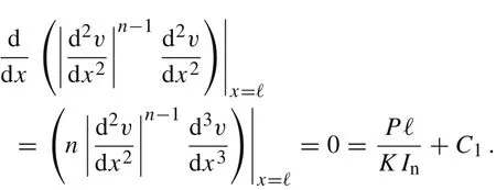

Note that Eq. (19) implies that>0 if P >0 and thatif P <0. Therefore, the construction of the solution is similar for these two cases.It follows for the analytic solution v(x)

so

where the integration constants C3and C4can be determined by employing the boundary conditions Eq.(16).We have
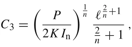
and

Finally, the exact solution of the boundary value problem Eqs.(15)-(17)is given by

Let us introduce the following constant

which will be frequently used throughout the paper. The solution from Eq. (20) can be also written as a function of non-dimensional spatial variable ˆx = x/ℓ ∈(0,1) as follows

In the case of the cantilever beam under uniformly distributed pressure,we have

Therefore,the stiffness coefficient in Eq.(7)is given by

If n = 1,then we recover the well-known result for Hook’s materials

see Ref.[23].
2.2 Cantilever beam under point load at the tip
Let us consider the cantilever beam under the point load at the tip,see Fig.2.The governing equation is

subject to the boundary conditions

and

Integrating twice Eq. (24) and employing the boundary conditions Eq.(26)we get


Fig.2 Cantilever beam under point load at the tip
Notice that Eq. (27) implies>0 if F >0, and the vice versa,<0 if F <0.So,both cases can be treated analogously.We have

and consequently

where the integration constants C1and C2can be determined by employing two boundary conditions from Eq.(25).Then,we have
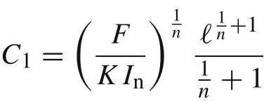
a nd

The analytic solution for the cantilever beam under the point load at the tip is given by

The solution expressed as a function of non-dimensional variable= x/ℓ ∈(0,1)reads as

Remark 1 The solutions given by Eqs.(22)and(30)coincide asymptotically for n →∞.
Remark 2 Let δ(x) denote the delta Dirac distribution. The solution given by Eq.(30)can be also obtained by consideringthe cantilever beam with a point load at x = xF,xF∈(0,ℓ),subject to the boundary conditions from Eqs.(16)and(17).The exact solution to this problem has been found in Ref.[2]and it is given by
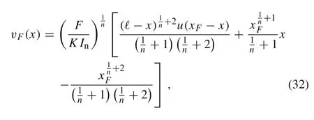

where

is a unit step function.Then,v(x)=coincides with solution from Eq.(29).
The corresponding stiffness coefficient for the cantilever beam with a point load at the tip is given by

where

If n =1,then we recover the linear case

where

see Ref.[23].
2.3 Hinged-hinged beam under uniformly distributed pressure load
Let us consider the hinged-hinged beam under uniformly distributed pressure load,see Fig.3.The governing equation reads as follows
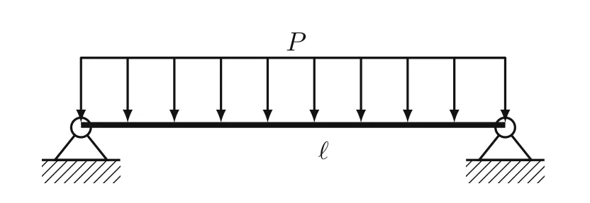
Fig.3 Hinged-hinged beam under uniformly distributed pressure load

subject to the boundary conditions

and

Integrating Eq.(34),yields

where C2=0 and C1=-due to=0 from Eqs.(35)and(36).Therefore,Eq.(37)can be written in the form

Notice that Eq. (38) implies<0 if P >0, and the vice versa>0 if P <0.Therefore,both cases can be proceeded in the similar way.We obtain

Let us make the following substitutionHence, the last differential equation becomes

Integrating Eq.(39)twice results in

Employing the boundary conditions v(0) = v(1) = 0, we get C4=0 and

The last integral can be expressed in terms of the Euler-Beta integral

see Ref.[27].To this end,we change the order of integration according to Fubini’s theorem
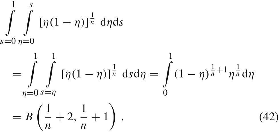
Consequently,we have

and

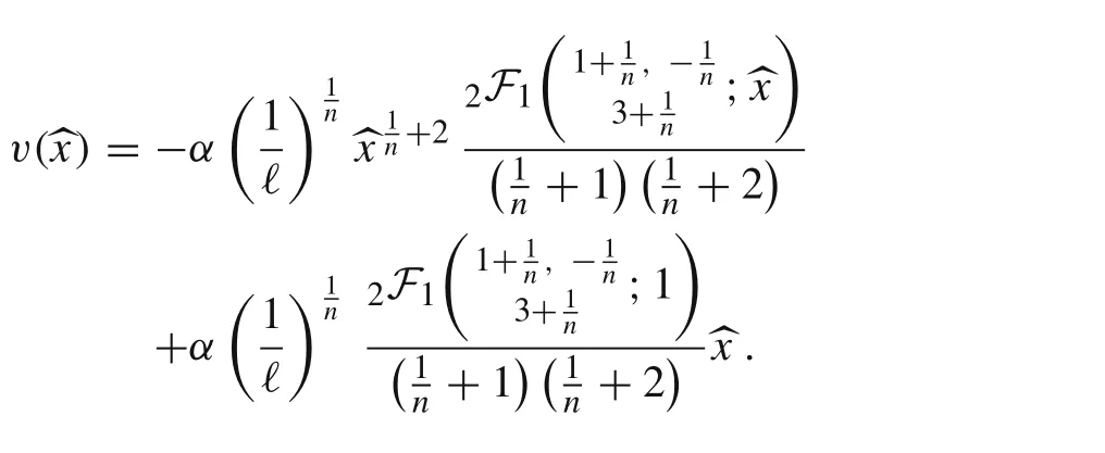
Remark 3 Symbolic integration in Maple applied to Eq.(39)yields

and


where |z| <1 and (q)kdenotes the Pochhammer symbol given by

see Ref.[28].For complex arguments z with|z|≥1 it can be analytically continued along any path in the complex plane that avoids the branch points 1 and infinity. The functionis the most usual type of generalized hypergeometric seriespFqdefined as

It follows from v(0) = 0 and v(1) = 0 thatand C4=0.Then,the exact solution is also given by
In order to find the maximum of v,we need the following
Lemma 1 Let n >0.Then,it holds true

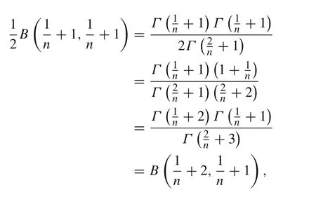
due to the identity B(p,q) =p,q >0,see Ref.[27],and Γ(x +1)= xΓ(x),x >0.
In fact,we have
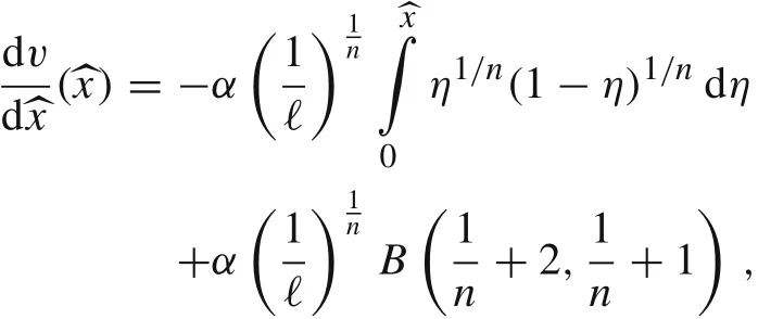
Corollary 1Let F >0.The maximum value of v(x)occurs at x =ℓ/2 and it is given by
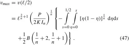
Proof It follows from Eq.(43)that

Remark 4 Alternatively,the maximum of v(x)can be written as follows
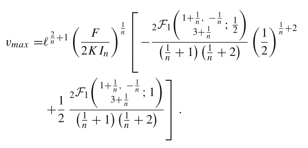
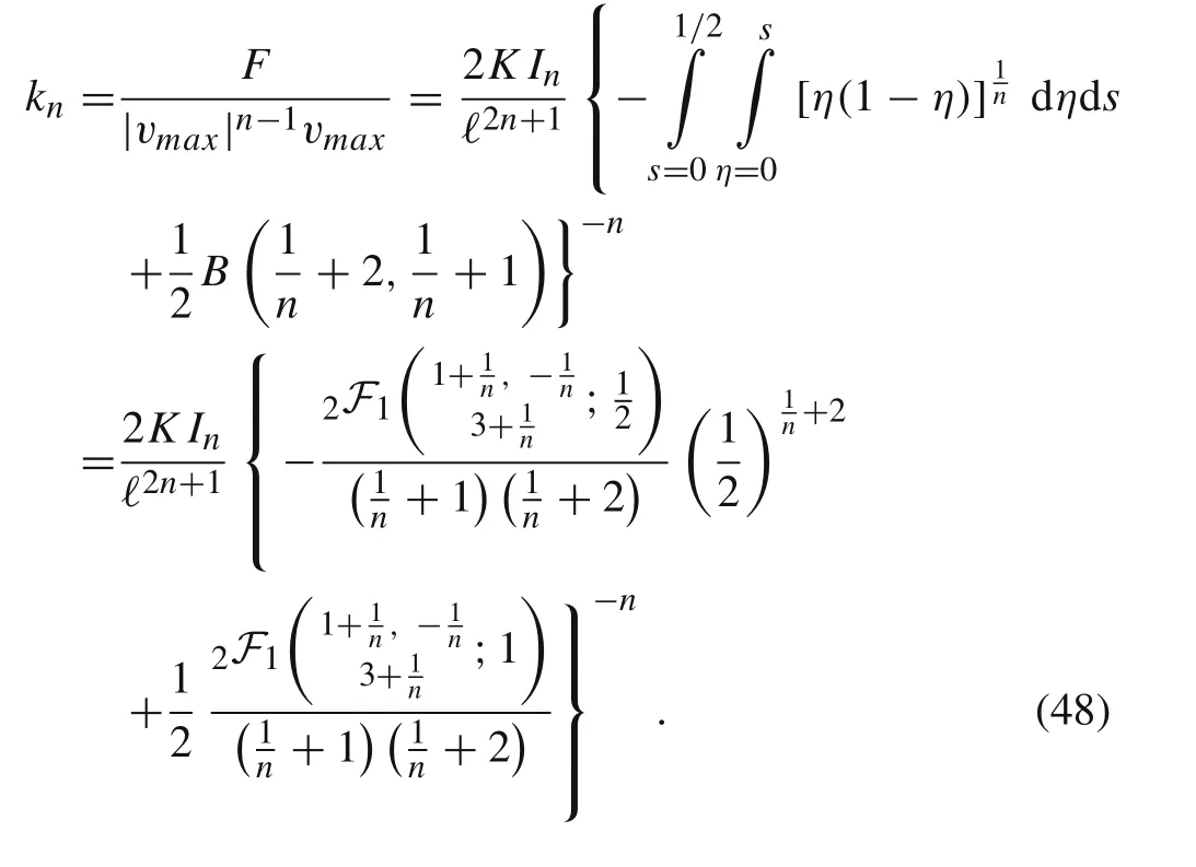
From Lemma 1 and Remark 4 we conclude that the corresponding stiffness coefficient is given by
In the case of n =1,we have

subject to v(0)=0,v(ℓ)=0.Then,
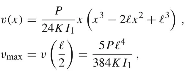
and the corresponding stiffness coefficient is given by
see Ref.[23].
2.4 Hinged-hinged beam under point load in the middle
Let us consider the hinged-hinged beam under the point load in the middle, see Fig. 4. The governing equation for the displacement v(x)reads as follows subject to the boundary conditions from Eqs.(35)and(36).We are looking for v(x)which is continuously differentiable.Integrating Eq.(49)twice yields


Fig.4 Hinged-hinged beam under point load in the middle

from which we infer

Integrating twice yields

The four integration constants can be found from the boundary conditions v(0) = 0, v(ℓ) = 0 and two continuity condition on v(x)andat x =ℓ/2.It follows that C2==0 and
Therefore,
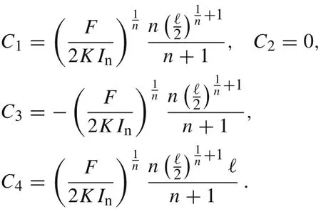
The deflection of the hinged-hinged beam under the point load in the middle reads as follows
The solution expressed as a function of non-dimensional= x/ℓ ∈(0,1)reads as
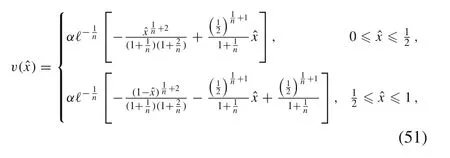
while the stiffness coefficient is given by

where

If n =1,then we recover the linear case

see Ref.[23].In Table 1 we want to summarize the obtained results.
3 Effective mass
Let us consider the cantilever beam of length ℓ and mass m.We approximate the deflections of the beam at its free end by X(t)that describes the oscillations in the one-degree-of freedom spring-like model. Our goal is to study the mass lumped model for the power-law Euler-Bernoulli cantilever beams made of the well-known power-law materials specified in Table 3. First, we consider the following initial value problem for the deflection of the cantilever beam at its tip


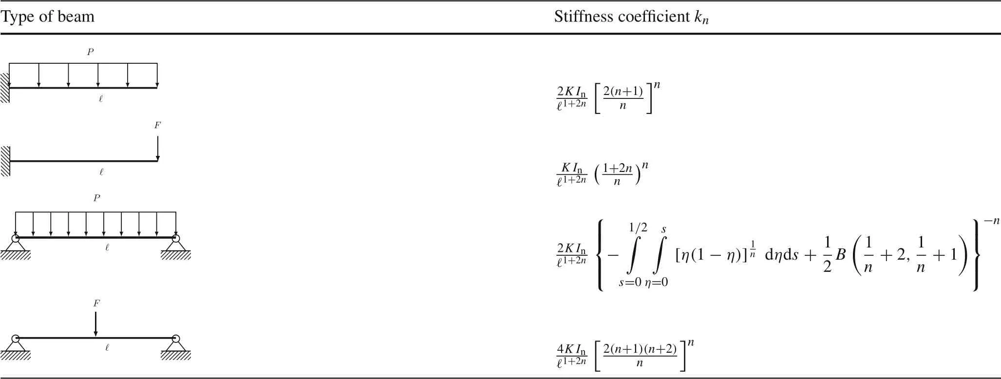
Table 1 Generalized stiffness coefficients kn for various types of power-law beams of length ℓ
or equivalently

with
subject to the initial conditions

The external force F acts at the tip only at t =0 and is immediately released.Here,meff(n)stands for the effective mass.We will use the so-called Rayleigh method to determine the equivalent mass meff=meff(n)for the mass lumped model of the cantilever beam.For this,let the kinetic energy of the cantilever beam be written in the form of

where ut(t,ℓ)is the velocity of the cantilever tip with a point load at time t. According to Eq. (29) the deflection of the beam v(x)can be expressed as
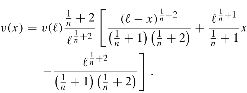
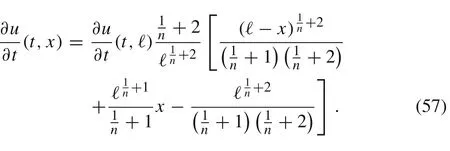
In the method of Rayleigh[23],it is assumed that

Then, Eq. (56) is differentiated with respect to time while keeping x fixed
Next,the kinetic energy of the whole beam of length ℓ can be calculated as

Then,the outcomes of Eqs.(55)and(58)are equated which leads to
Corollary 2The effective mass for the cantilever power-law beam of mass m and under the point load at the tip is given by

where

is the effective mass coefficient. Especially, in the case of n =1 we have

see Ref.[23].
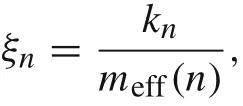
Taking into account Eqs.(33)and(59),we rewrite ξnin the exact form

Notice that

Finally,we present in Table 2 the effective mass coefficients for all types of considered beams which can be derived by analogy to the case of the cantilever beam with the load at the tip. The derivation of the complicated formula for the effective mass coefficient in the case of the hinged-hinged beam will be published in the separate paper.
4 Vibrating cantilever beam
Multiplying the differential Eq.(53)by ˙X(t)and integrating twice,yields the implicit formula for the solution X(t)as

where
The periodic solution X(t)can be also expressed explicitly in terms of the generalized trigonometric functions as follows[21,22]
Here, the generalized sine function sin2,n+1(t) is defined as solution component x1(t) of the following initial value problem for the system of first order ordinary differential equations(ODEs)

where φ(x2)= x2and ψ(x1)=|x1|n-1x1,cf.Refs.[29,30].Notice that the angular frequency ωndepends on the initial deflection X(0)unless the beam obeys Hook’s law(n =1).The period of the oscillations can be derived from Eq.(60)for X(0)=
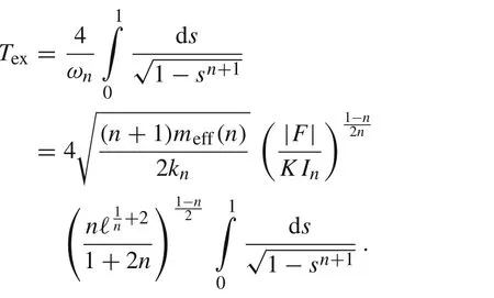
The frequency of the oscillations is given by

where

stands for the generalized Euclidean number Pi.In the case of Hook’s materials,the natural frequency can be calculated as ω1=
In the case of the beams made of linear materials(n =1)[31,32],the solution in form of Fourier series can be obtained by the separation method

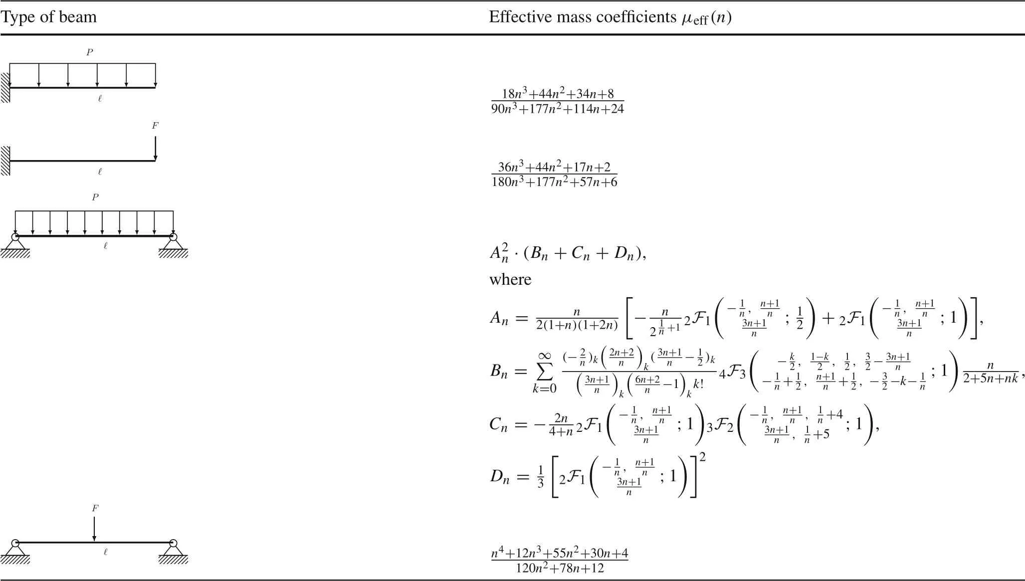
Table 2 Effective mass coefficients μeff(n)for various types of power-law beams
where

the Fourier coefficients Akare given by
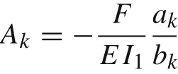
with
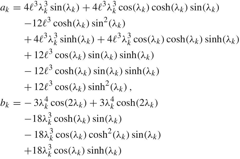

and λkare positive roots of the equation cos(λk)cosh(λk)=-1.
Notice that the frequency of the first mode

is already close to the natural frequency in the lumped mass model

5 Comparison with Galerkin low-order approximation
Let us consider the Galerkin ansatz of the form u1(t,x)=Ψ(x)q(t)≈u(t,x),
where the spatial basis function Ψ(x)is chosen as
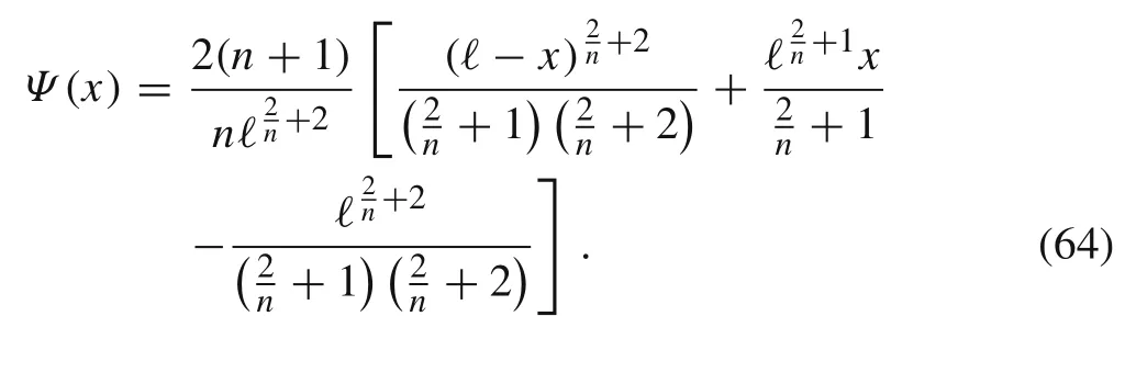
The n-dependent basis function Ψ(x) originates from Eq.(20). Notice that Ψ satisfies the boundary conditions from Eq.(3)and Ψ(ℓ)=1.Then,the Galerkin equation reads as follows
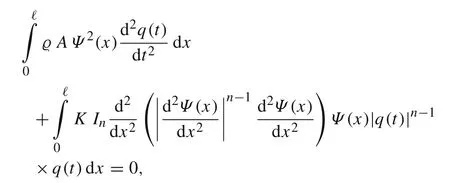
or equivalently

where
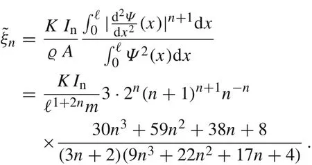
It follows from the boundary and initial conditions for the cantilever beam problem Eq.(2)that u1(t,ℓ)=q(t),


Table 3 Parameters for the well-known power-law materials
and

In our simulations, we consider the power-law Euler-Bernoulli cantilever beams of length ℓ with either circular cross-section A of radius R >0, or a rectangular crosssection A of height h and width b,respectively.In the case of beams with circular or rectangular cross-section A, the constant moments of inertia defined in Eq.(14)are given by

respectively, see Ref. [34]. We present simulation results for beams of length ℓ = 50.8 cm and with both types of cross-section.The parameters for various types of power-law materials and the corresponding stiffness coefficients and the moment of inertia are specified in Tables 3 and 4.The circular cross-section of the beam is of radius R = 0.5 cm whereas the rectangular cross-section is of height h = 0.635 cm and width b = 2.54 cm. The initial deflection at the tip is X(0) = q(0) = 2.54 cm.In Fig.5 we plot the solutions of Eqs. (53) and (65) for the beam made of Copper annealed(n =0.54,ϱ =8.91 g/cm3,K =315 MPa,see Ref.[5,33])and for the same initial conditions from Eqs.(54)and(66),(67).We observe that the frequencies of oscillations for both beams are different. This confirms our prediction that the natural frequency of the oscillations depends on the shape of the beam cross-section due to Eqs.(33),(61),and(68).
Now,we compare ξnwithTo this end,we plot in Fig.6(a)the quotient

for n ∈[0,1].We see that r1= 910/891 = 1.0213...,and rnis almost 1 for all n ∈[0,1].Notice that=1,and r0.54=1.0384....

Fig.7 Mass lumped model and low-order Galerkin solutions with n-independent basis function defined in Eq.(70),n =0.54
Alternatively, we can use the n-independent polynomial basis function

for the Galerkin ansatz.Then,

and

The corresponding quotient rnis shown in Fig. 6(b). We see that r1= 910/891 = 1.0213...,and the quotient rnin contrast to that one defined in Eq.(69)is almost 1 only for the range of n ∈[1/2,1].Notice also that= 26/45 =0.5777...,and r0.54=1.0094....
In Fig. 7 we plot the mass lumped and Galerkin solutions of Eqs.(53)and(65),respectively,for the same set of parameters as in Fig. 5. In the particular case of n = 0.54,the Galerkin solution obtained by using the polynomial basis function from Eq.(70)is closer to the mass lumped solution than the Galerkin solution obtained by using the n-dependent basis function from Eq.(64).The solution to our mass lumped model and the low-order Galerkin approximation coincide well.
6 Conclusions
The lumped parameter systems for nonlinear elastic beams governed by the Hollomon’s power-law stress-strain equation are established for several standard geometric and loading conditions of structural beams which has generalized the theory for linear materials. The derived lumped-parameter systems used as approximations of the structural elements in applications are validated numerically and analytically for linear materials,and the approximate solutions to problems for cantilever beams made of power-law materials are compared with the low-order Galerkin solutions. The derived mass lumped model parameters are functions of the power-law index. In the case of the linear materials, they coincide with the well-known coefficients from the literature. We showed numerically that our approach based on the lumped parameter models can be successfully applied to study dynamics of the cantilever power-law beam. Also,this approach can be applied to power-law beams with other boundary conditions. The calculated mass lumped model coefficients for various types of beams are summarized in Tables 1 and 2.Our results can be useful for dynamic pullin analysis of micro-electro-mechanical structures made of power-law materials. This will be investigated in the forthcoming papers.
AcknowledgementsThe research was supported by the Nazarbayev University ORAU grant “Modeling and Simulation of Nonlinear Material Structures for Mechanical Pressure Sensing and Actuation Applications”.
杂志排行
Acta Mechanica Sinica的其它文章
- Geometric and material nonlinearities of sandwich beams under static loads
- Coupled thermoelastic theory and associated variational principles based on decomposition of internal energy
- Transient growth in turbulent particle-laden channel flow
- Experimental and theoretical investigation of the failure behavior of a reinforced concrete target under high-energy penetration
- Revealing the high-frequency attenuation mechanism of polyurea-matrix composites
- Efficient algorithm for 3D bimodulus structures
