A new absolute nodal coordinate formulation beam element with multilayer circular cross section
2020-05-06PengLanQinglongTianZuqingYu
Peng Lan · Qinglong Tian · Zuqing Yu
Abstract A systematic numerical integration method is applied to the absolute nodal coordinate formulation (ANCF) fully parameterized beam element with smooth varying and continuous cross section. Moreover, the formulation for the integration points and weight coefficients are given in the method which is used to model the multilayer beam with a circular cross section. To negate the effect of the bending stiffness for the element used to model the high-voltage electrical wire,the general continuum mechanical approach is adjusted.Additionally,the insulation cover for some particular types of the wire is described by the nearly incompressible Mooney-Rivlin material model. Finally, a static problem is presented to prove the accuracy and convergence properties of the element,and a dynamic problem of a flexible pendulum is simulated whereby the balance of the energy can be ensured.An experiment is carried out in which a wire is released as a pendulum and falls on a steel rod. The configurations of the wire are captured by a high-speed camera and compared with the simulation results. The feasibility of the wire model can therefore be demonstrated.
Keywords Circular cross-section beam · Absolute nodal coordinate formulation · Electrical wire modeling ·Contact
1 Introduction
1.1 Background
Dynamic analysis of a transmission wire remains a quite challenging topic because of its geometrical nonlinearity and complex structure. This is especially true in cases in which transmission facility construction is in process, and the wire is tensioned and placed on a transmission tower by a tension machine.If a tension failure accident happens,for example, the wire is broken, or the tension machine malfunctions, the wire will fall and cause damage to the existing facilities under it. Therefore, it is necessary to set up a protective frame to hold the falling wire. One of the most important preconditions to design the frame is the accurate prediction of the dynamic behavior of the wire.The absolute nodal coordinate formulation (ANCF)developed by Shabana [1], on the other hand, has been successfully used in large rotation and deformation problems. The global position and gradient vectors are utilized as the nodal coordinates so the transformation matrix is not needed. As a result, the mass matrix is constant, and no Coriolis or centrifugal forces are included in the equation of motion. The ANCF cable element is the most widely used finite element in wire modeling. In a study published by Berzeri et al. [2, 3], a planar cable element was proposed and a comparative study between different elastic models was given. In addition, Sugiyama et al. [4] developed a spatial cable element and compared the simulation results with the analytical procedure. Research by Gerstmayr and Shabana [5] provided a strategy for multi-body system dynamic implementation of a cable element, and the authors built a pantograph/catenary mode. In other works, Liu and Hong [6] derived variational motion equations of a flexible body with both the shear strain and the transverse normal strain taken into consideration, and Pappalaro et al. [7] developed an effective method to control the contact force which arises from the pantograph/catenary interaction. A general sliding joint formulation was given, which allowed for the use of the ANCF cable element. In other studies, Kulkarni et al. [8]built a continuum mechanics-based pantograph/catenary model and investigated two different approaches for formulating the interaction contact force, and Wang et al. [9]proposed a multi-zone contact approach of thin beams to accurately detect the contact situation between beams.Other researchers include Hu et al. [10], who summarized the dynamic modeling, numerical simulation, and experimental validation of soft machines, and Zhao et al. [11],who developed a simplified interplanetary kite-craft accelerated by radiation of the Sun(IKAROS)model using the absolute-coordinate-based method. In addition, Xu and Liu [12] proposed a novel modeling method for studying the dynamic behavior of nonlinear materials based on ANCF,while Zhang et al.[13]proposed an adaptive ANCF(AANCF) method, and presented a theoretical model of a planar AANCF cable.
However, some shortcomings can be found in the implementation of a cable element. First, the Euler-Bernoulli beam assumption makes the cable cross section rigid and always perpendicular to the centerline.That makes the cable element unable to describe the local deformation of the cross section at the contact area. Second, the transmission wire is obtained by twining the aluminum wire around the copper core at the manufacture stage. This is a typical multilayer material structure, which cannot be described by a cable element because of the lack of material coordinates at the transverse direction. For these reasons, the fully parameterized beam element needs to be introduced into the description of the details of the wire.To address this need,Omar and Shabana[14]proposed a shear deformable beam element in the planar case, and Kerkkanen et al. [15] proposed a lower-order shear deformable beam element which used linear polynomials to interpolate the displacement field. A selective integration of the strain energy was given in order to solve the locking issue. In another study, Garcia-Vallejo et al. [16] analyzed the curvature thickness locking issue in the traditional fully parameterized beam element, and noted that the difference between the orders of the polynomials used in the axial and transverse direction was the source of the problem.A threenode beam element with position and transverse gradient vectors at each node was proposed. Simulation results showed that only half the number of elements was needed to achieve the same accuracy when compared with a conventional shear deformable beam element. In further research, Mikkola et al. [17] replaced the lateral slope vector by a vector that described the orientation of the beam cross section.The number of degrees of freedom was substantially reduced without a loss of accuracy. A study by Shabana and Yakoub [18, 19] proposed a three-dimensional (3D) ANCF fully parameterized beam element,and the authors presented two types of 3D beam elements.One of the elements had two nodes,and the other had four nodes. The method was able to be systematically used for solving large deformation problems, particularly in manufacturing applications in which the cross section of the element does not remain rigid. A more efficient 3D beam element was proposed by Dufva et al. [20], which employed a cross-sectional coordinate system to define strains,while Gerstmayr and Matikainen[21]constructed a two-node beam element with 48 degrees of freedom by increasing the order of the interpolation polynomials. The locking issue of the beam element was improved with standard selective reduced integration techniques. In the article presented by Sugiyama and Suda [22], the gradient transformation of a strain tensor was discussed as a way to deal with the initially curved beam. The Hellinger-Reissner variational principle was used to avoid the problem of shear locking. In addition, Orzechowski and Shabana [23]proposed a high-order ANCF beam element that was effectively used to capture warping and eliminate Poisson locking.
1.2 Scope of the investigation
The scope of this investigation is to build a transmission wire model with an ANCF fully parameterized beam element, which makes it possible to describe the multilayer material of the wire and the local deformation of the cross section. However, an obvious problem that needs to be firstly addressed is that the use of linear polynomials to interpolate the element transverse dimension leads to a quadrangle cross section of the fully parameterized beam element. In other words, it is impossible for the conventional 3D beam element to describe the circular cross section. Nonetheless, a distinct method of integration proposed by Orzechowski [24], which allows for efficient analysis of the ANCF beam elements with a circular cross section, can be used. This paper will give a further discussion of how to implement this method to depict the multilayer material property of the wire. Furthermore, an experiment of a wire fall on a rigid rod is designed to verify the model developed in this investigation.
The remainder of the paper is organized as follows. In Sect. 2,the kinematic description of a new multilayer beam element with a circular cross section of ANCF is proposed.The method of integration for a smooth varying and continuous cross section is presented. In Sect. 3, the elastic force of homogeneous, isotropic, linearly elastic materials and incompressible Mooney-Rivlin materials are introduced. In Sect. 4, an experiment is carried out, in which a wire is released as a pendulum and impacts a steel rod. In Sect. 5, the numerical results are presented and discussed.Section 6 provides concluding remarks.
2 Kinematic description
The traditional fully parameterized beam element based on ANCF is proposed by Shabana and Yakoub [18, 19].The element displacement field is discretized as follows
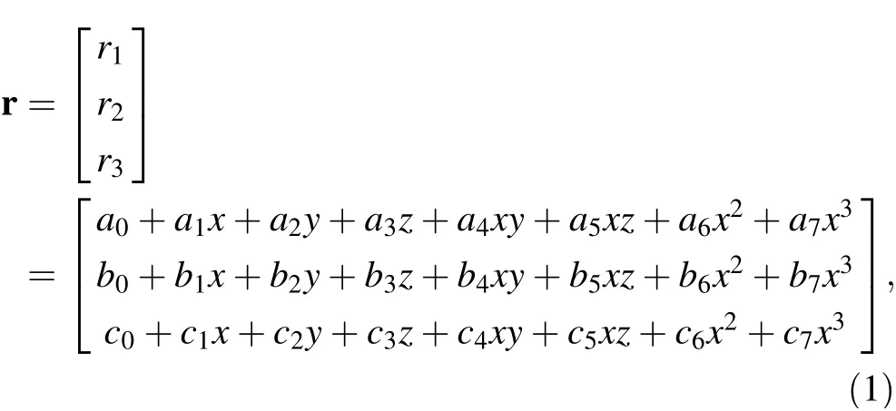
where r is the global position vector, and ai, bi, ci, i=0,1,2,:::,7 are the coefficients of the interpolating polynomials. The element uses a global position vector and gradient vectors along three directions at two ends as nodal coordinates, which can be written as


where S=S x,y,z( ) is the element shape function matrix.The shape functions S can be obtained by Eqs. (1)-(3),which can be written as

where I is the 3 × 3 identity matrix, and the shape functions sifor i = 1,2,…,8 are given as follows

In this equation, l is the length of the element in the undeformed state.ξ,η and ζ are the dimensionless material coordinates.
From the formulation of the element shape function given in Eq. (5), one can find that the interpolation functions used on the transverse directions are linear polynomials. In other words, the cross section of the beam element is rectangular in the reference configuration,and it will always remain quadrilateral, as shown in Fig. 1a. For this reason, when carrying out the numerical integration over the whole element, the integration in the three directions is naturally independent, as shown in Eq. (6)

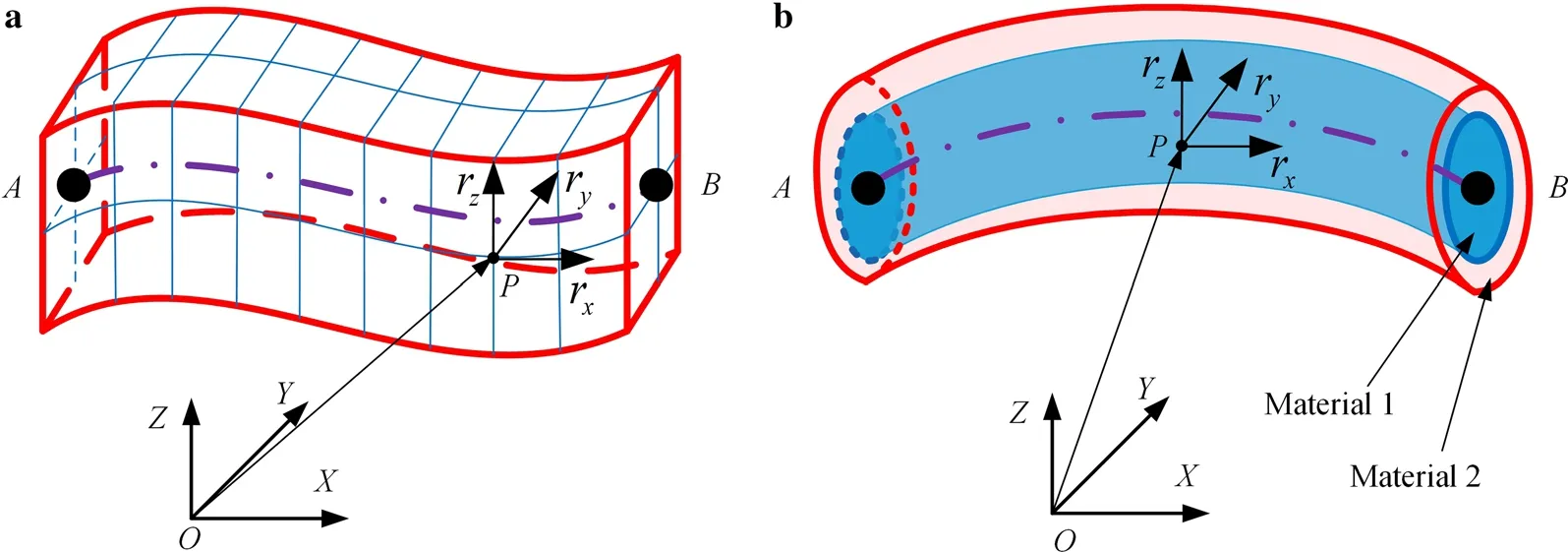
Fig. 1 Beams with different cross section.a Conventional rectangular cross section fully parameterized beam element.b Circular cross section fully parameterized beam element
where f is the integrated function. It can be, for example,the mass matrix or elastic force vector. The ANCF cable element, which is widely used in wire modeling, is based on the Euler-Bernoulli beam theory. It uses the polar moment of inertia to evaluate the bending stiffness.Therefore, an implicit assumption that the element has a circular cross section is introduced. On the other hand, the Euler-Bernoulli beam has a rigid cross section,so the cable element is unable to describe the deformation of the wire cross section.The absence of the transverse coordinate also implies that the multilayer structure of the wire cannot be modeled by a cable element.To address this,Liu et al.[25]proposed a method of dividing the thickness of the thin plate structure into several subintervals with different material properties. In this way, the composite laminated plate structure can be modeled.In order to use this method,the traditional fully parameterized beam element should be improved to describe the circular cross section. Therefore,Patel et al. [26] proposed a multilayer beam based on subdomains with different material properties in a single element,and Orzechowski and Janusz[27]proposed a twolayer beam model with two elements.Inevitably,there will be gaps between elements.In order to eliminate those gaps,connectivity points are added between the elements,which results in a multilayer beam with a complex structure and more degrees of freedom.In a study by Orzechowski [24],the authors proposed a distinct method of integration that can change the shape of the integration area from a rectangle into a circle.This means that the fully parameterized beam element can achieve a circular cross section without changing the shape function.In this section,the integration method will be further explored to make the fully parameterized beam element suitable for modeling the multilayer structure of a wire, as shown in Fig. 1b.
For the beam element, the axial dimension is obviously independent of the cross section; hence the integration given in Eq. (6) could be denoted as

where A is the cross-section area. Let

Then Eq. (7) can be written as

By Eq. (9),the volume integral is divided into two parts:an axis and cross-section integral. Integrals over the cross section can be written in the following form

where a,b,c(η),d(η) are the range of the cross section,respectively.The integration in the cross sections works for smooth varying and continuous cross sections, such as circular or triangle cross sections.In this investigation,this method is used to model the multilayer beam with a circular cross section. In another work, Ronald and Kim [28]presented a survey of integrals over a unit disk. They transformed the unit disk integration into a square one,which is shown as

Define t=sin θ, then Eq. (11) can be written as

Equation (12) can also be written as
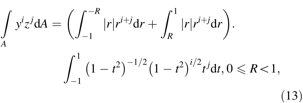
where R is the inner radius of the ring cross section. If R=0,A is the circular cross-section area.Once R/=0,A is the ring cross-section area.Obviously,the weight functions

where n is the order of the quadrature. One can use the method of undetermined coefficients to obtain the weight coefficient and integration points.On the right-hand side of Eq. (13), the other part of integration can be written as

The integration points can be written as

When the integral region is not a unit disk, the circular area can be transformed into

where R2is the outer radius of the ring,and R1is the inner radius. The integration over the circular cross section can be written as

where η(m,k)=q(m)r(k),ζ(m,k)=t(m)r(k), t m( ) and q m( ) can be written as

When n is even,there will be n2integration points.Once n is odd, there are n2- n + 1 integration points. If function h is a polynomial, the presented quadrature one can reach the accuracy with the order of 2n - 1. As illustration,two examples are presented,which are R1=0,R2=1 and R1=0:5,R2=1, respectively. In Tables 1 and 2, the weights w and parameters r,t and q are given.In Fig. 2,the distribution of the integral nodes is shown.
By using the method above,the integrations that should be performed in the element with a circular section can be obtained.
The element mass matrix, which is given in Ref. [18],can be written as follows

where ρ and V are the density and the volume of the element,respectively.The mass matrix of the wire model with multilayer materials can be written as

where ρ1and V1are the density and volume of the inner ring,respectively.ρ2and V2are the density and volume of the outer ring, respectively. Therefore, all the layers with different material properties can be described with theelement cross section. The complex composite structure can be described by fewer degrees of freedom to obtain higher simulation efficiency.
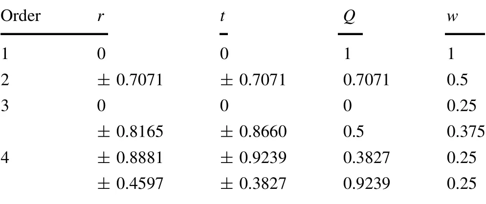
Table 1 Circular cross-section quadrature point (R1 =0,R2 =1)
3 Element elastic models
3.1 Modified elastic force of homogeneous isotropic material
In high-voltage wire modeling, the material property is a difficult topic because of its complex structure.For example,the wire consists of a mount of aluminum threads twisted around the cooper core. As a result, the gaps between the threads cause the wire to display much weaker bending stiffness and slightly weaker stretch stiffness compared with the isotropic metallic sticks with the same dimension and material parameters. Therefore, the isotropic homogenous material which is widely used in engineering applications to describe the metallic material property should be modified.A novel method is proposed in this section, which can weaken the bending stiffness in this case when the general mechanical approach is applied. In the general continuum mechanical approach,the generalized Hooke’s law gives the relationship between the strain ε and the stress σ

where D is the matrix of elastic coefficients.
The elastic energy function U can be written as the tensor double product of the strain and the stress

It is known that when a beam is bent, the centerline is assumed to not be stretched.As we can see in Fig. 3,in the cross section of the beam, one side of the central line is stretched, and the other side is compressed. It is the integration of the axial stress over the whole cross section that creates the bending stiffness of the beam.If the integration of the axial stress is only done over the centerline,the beam will lose the bending stiffness.
Therefore, the first item in Eq. (23) is negated, and its integration can be written in the following form

where A1is the area of the cross section, ω is the weakening coefficient, 0 ≤ω ≤1. It depends on the structure type and the material of the wire.Its value can be obtained by experiments.
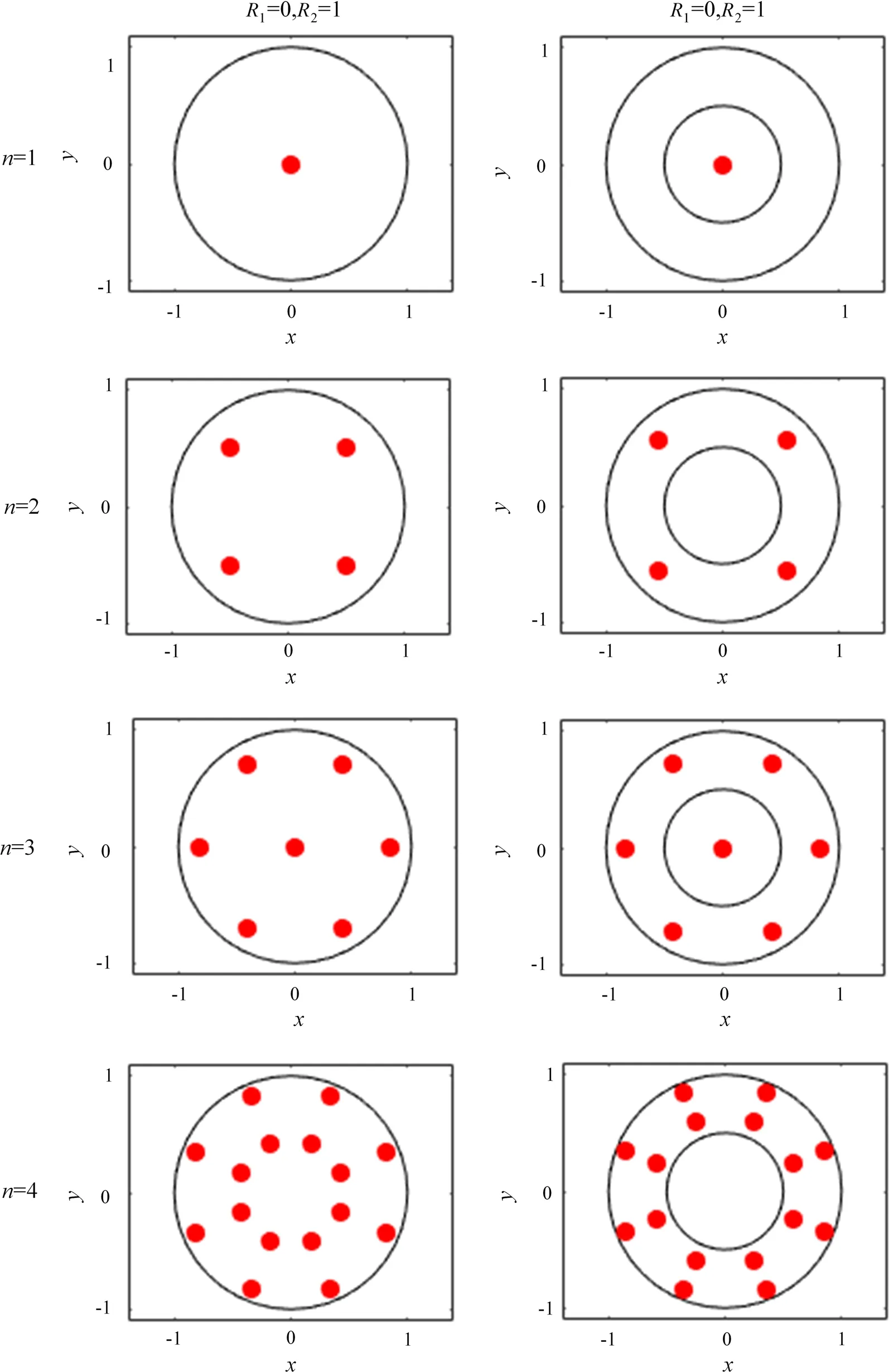
Fig. 2 Distribution of the integral node
Accordingly, the total strain energy of the element can be written as
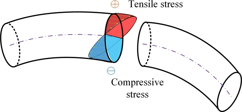
Fig. 3 Stress analysis of a bent beam

The element elastic force is derived by differing the strain energy with respect to the element nodal coordinate vector
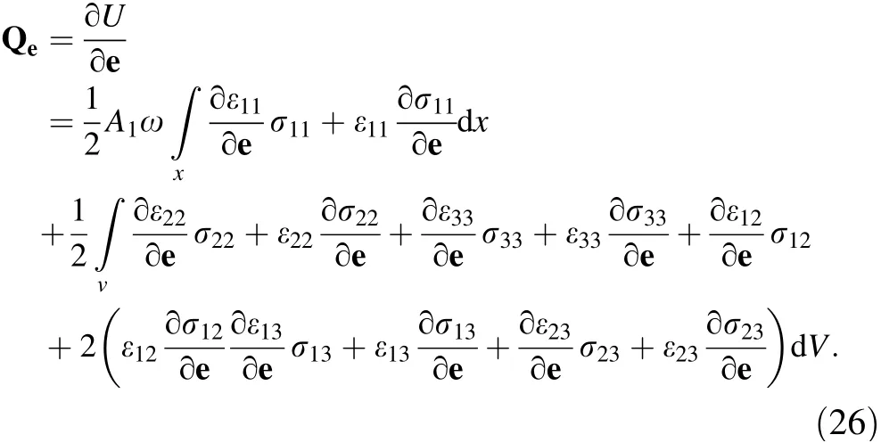
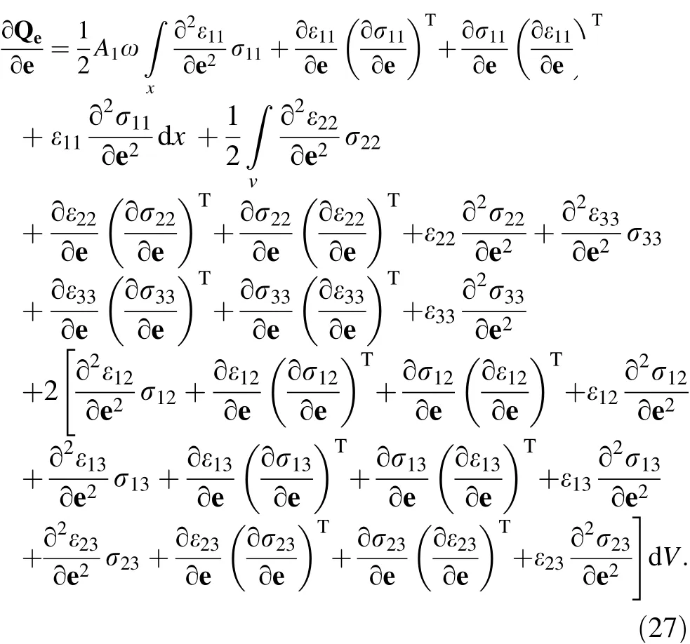
If the implicit solver is used, the Jacobian matrix of the elastic force with respect to the element nodal coordinate vector should be evaluated
3.2 Elastic force of incompressible Mooney-Rivlin materials
In particular,the wire which works at a voltage lower than 50 kV is usually covered by rubber for insulation,which is typically nearly incompressible material. In the general Hooke’s law,the linear relationship between the stress and the strain is applied. If the nearly incompressible material property is required, the Poisson ratio has to be near 0.5.Consequently, the Poisson locking issue will occur,resulting in a significant decline in simulation efficiency.On the other hand, the Mooney-Rivlin constitution model is suitable for the nearly incompressible material. The strain energy formulation proposed by Rivlin [29] and Mooney [30] is

where the coefficients μrsare constant. I1, I2, I3are the three elastic invariables, which can be found in Ref. [31].Keeping different items will generate different models.There are only the first two items of Eq. (28) in the Mooney-Rivlin model

The incompressibility conditions I3=1 should be preserved. To this end, one can use the penalty method. The modified strain energy density function can be written as

The penalty energy term is

where k1= - (μ10+ 2μ01), k2= max(μ10, μ01) × 103to max(μ10, μ01) × 107. The values are recommended by Belystschko et al.[32].The incompressible material elastic force can be written as

The Jacobian matrix of elastic force can be written as

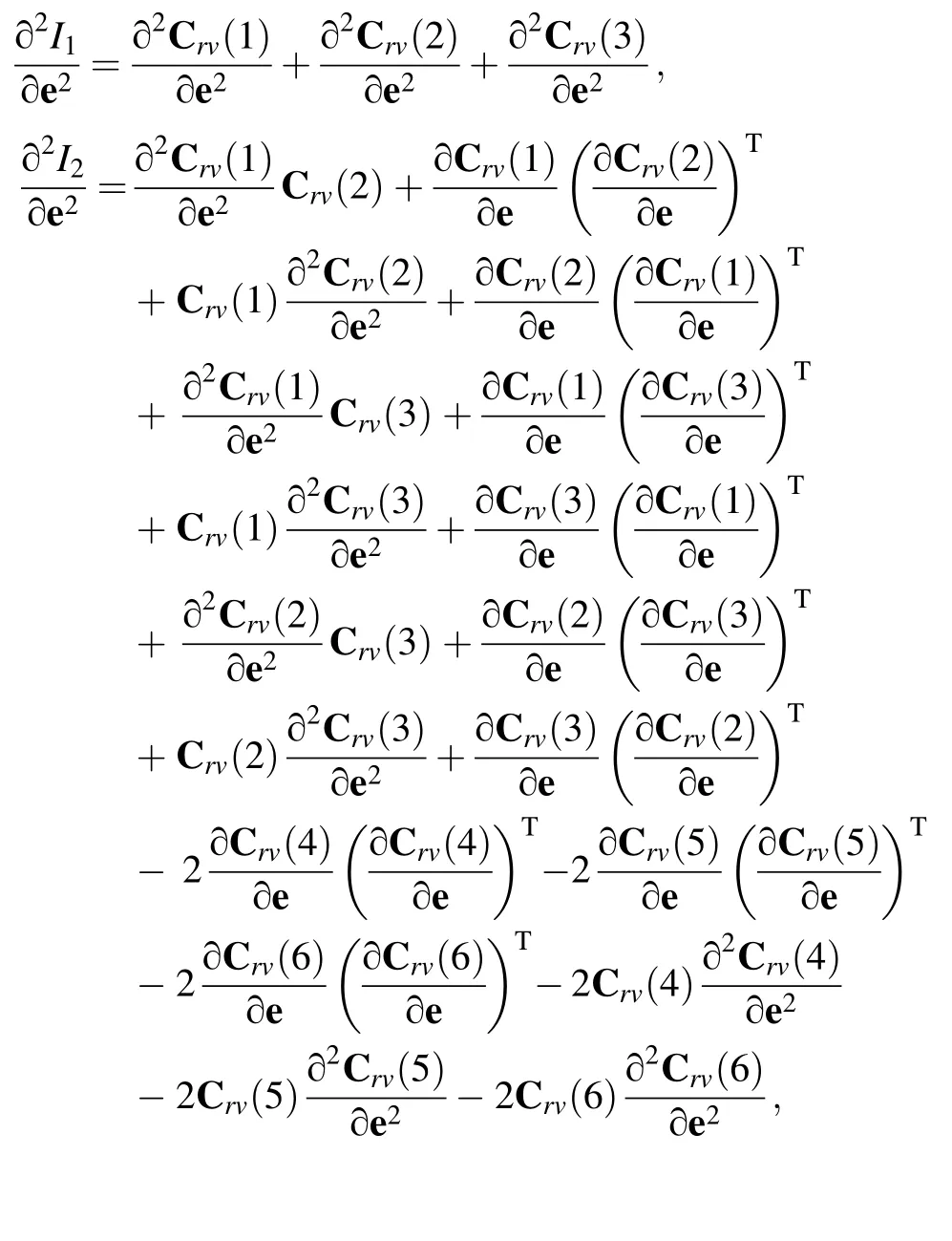
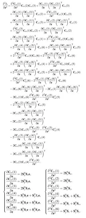
where the formulation of the first and second derivative itemsandcan be found in the Appendix.
4 Experimental research of the wire-rod contact
The purpose of developing the circular cross-section beam element is to predict the dynamic behavior of the wire when colliding with the protective rod. In order to test the performance of the proposed element,an experiment is set up.A wire is fixed at one end and is released from the horizontal state.Due to gravity,it will swing down and collide with a fixed steel rod. Since the deformation of the steel rod is much smaller than the wire,it will be considered as a rigid body in this research. Figure 4 gives a schematic view of the whole experiment. The configurations of the wire at different moments are captured by the high-speed camera.They are compared with the numerical simulation results to demonstrate the feasibility of the element (Table 3).
In existing research, the mortar method [33-35] is widely used to perform the contact. In this study, the contact is implemented using the minimal distance criterion[36-39]and the mortar method.In the simulation side,the penalty method is used to calculate the contact force between the wire and the rod. It is the most widely used method for the contact problem since its implementation is straightforward and the physical meaning is clear.
As shown in Fig. 5, P is an arbitrary point on the centerlines of the wire, and Q is an arbitrary point on the centerlines of the rod.The material coordinates of points P and Q are denoted asThe superscripts w and r represent the wire and the rod, respectively. The distance between points P and Q can be expressed as

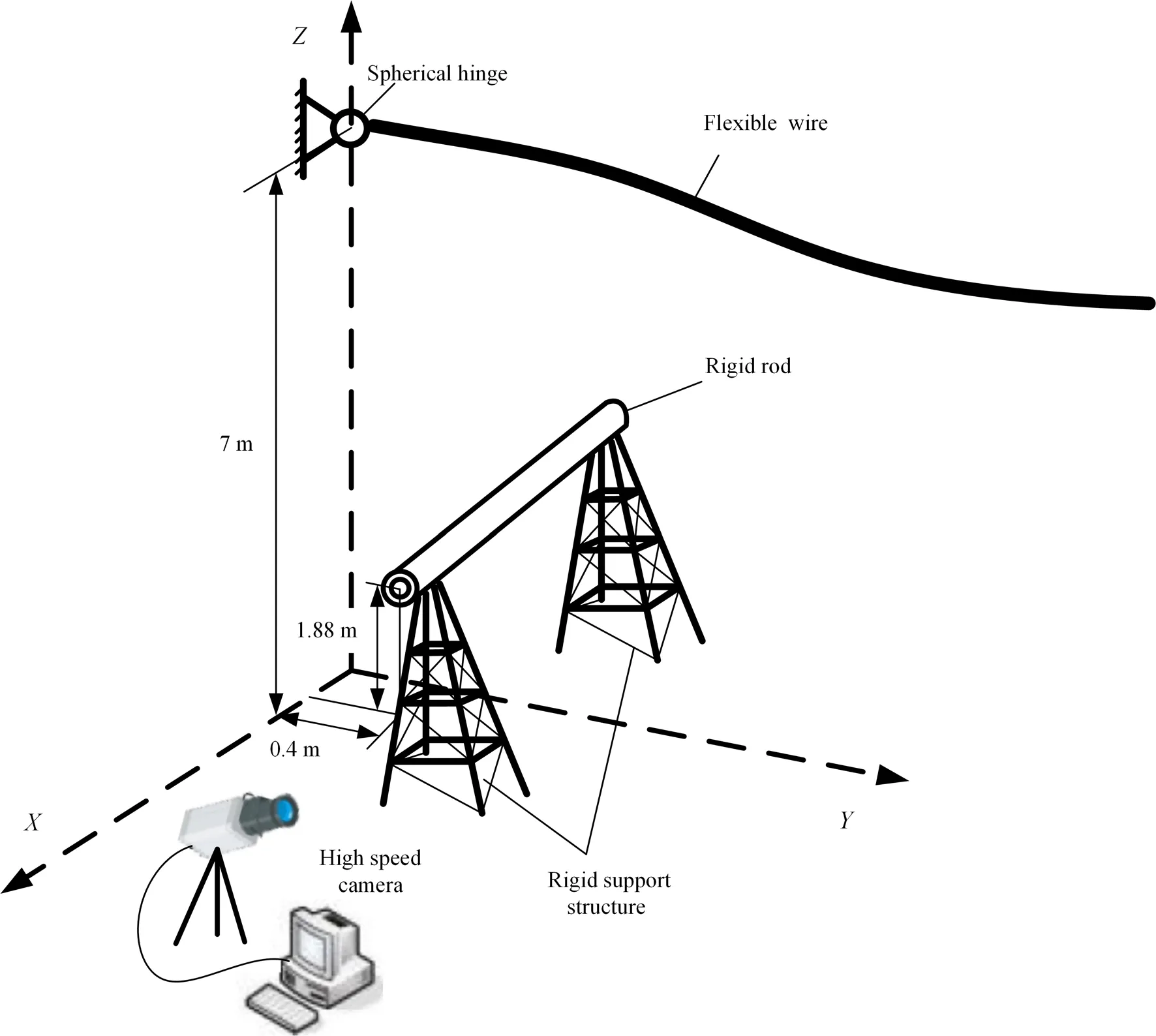
Fig. 4 Schematic view of wire-rod contact experiment

Table 3 Parameters of the wire and rod
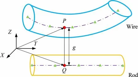
Fig. 5 Detection of the closest points between the centerlines
By using the minimal distance criterion, the minimal distance of the centerlines can be obtained.
RIis the radius of the wire, and RΠis the radius of the rod. If gmin>RI+RΠ, obviously the wire and rod are not in contact. Once gmin>RI+RΠ, the mortar method will be used to detect the contact.In this study,the cross section of the wire is deformable;therefore,the test points need to be set on the outer surface of the wire.In order to improve computing efficiency, only the points in the interval near point P are considered. As shown in Fig. 6, the test points can be express as

The distance between the test point and the surface of the rod can be express as

When the minimal distance of the test points and the rod is obtained, the contact criterion will be used T

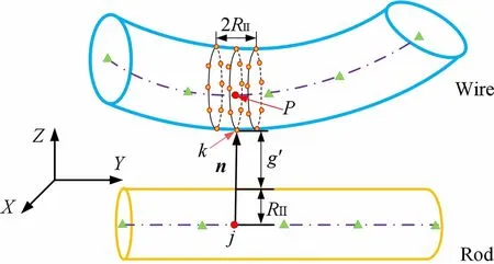
Fig. 6 Contact detection between the wire and rod
he normal contact force at the arbitrary contact points can be defined according to the penalty method as

where p is the penalty parameter,and n denotes the normal direction at the contact points, as shown in Fig. 6

Finally, the generalized normal contact force can be obtained

The friction force is based on the Coulomb model. The generalized contact force and friction force will be treated as external force in the system equation of motion. It is a set of second-order ordinary differential equations, which is solved by the generalized-α method in this investigation.
5 Numerical simulation and experimental validation
5.1 Statics problem
A static model is examined to verify the element elastic model. The small deformation problem is chosen in order to compare the simulation results with the theoretical results. A horizontal and a vertical force are imposed separately on the cantilever beam that contains two layers.The parameters of the beam can be found in Table 4.Since the elastic force of the element is a nonlinear function of the nodal coordinates, the static equilibrium equation is actually a set of nonlinear algebraic equations. The Newton-Raphson iteration method is used to find out the results, which are shown in Tables 5 and 6.
When the force F1= 1 N is imposed along the axis of the cantilever beam, which is shown in Fig. 7a, the elongation can be written as

The theoretical value of elongation Δl is 3.978 × 10⁻⁴m. The calculation values are showed in Table 5.
When the force F2= 1 kN is imposed perpendicular to the axis of the cantilever beam,which is shown in Fig. 7b,obviously, the deformation can be written as

The theoretical value of deformation Δz is 1.326 ×10⁻³m. The calculation values are shown in Table 6.
Obviously, as the number of elements increases, the convergence and accuracy are increasingly ensured.
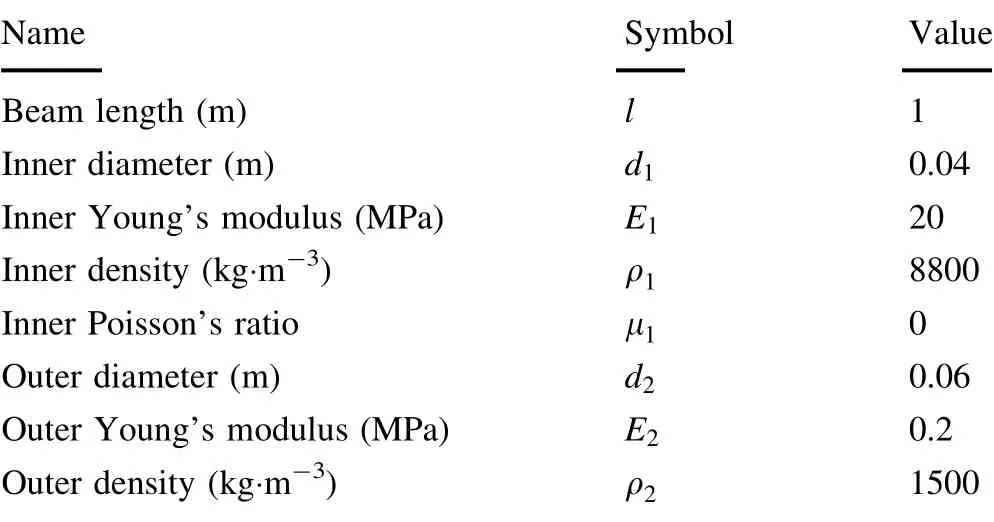
Table 4 Parameters of the beam
5.2 Physical pendulum
A flexible pendulum model is built to test the dynamic simulation procedure. An initially horizontally placed pendulum falls under the effect of gravity. The parameters of the pendulum are given in Table 4. The flexible pendulum is discretized by four elements. The configurations at different instances are given in Fig. 8. Figure 9 shows the variation of the kinematic energy Ek, the strain energy Ee,potential energy Egand the total energy Etwith respect to time.As can be clearly seen,energy is preserved for the whole simulation time. As a conclusion, the conservation of the total energy can be preserved. It also proves the feasibility of the dynamic simulation procedure.
5.3 Wire-rod contact experiment and computational simulation
The experimental results are shown in this section. Figure 10 gives a comparative view of the simulation results and the experimental results. It can be found that the simulation results fit the experimental results well.
In Fig. 11a,the vertical displacement of the first contact point on the wire surface is shown.In Fig. 11b-d,the norm strain ζXX, ζYYand ζZZare shown.
It should be noticed that after the gradient vectors are calculated to obtain the strain inside the element, they are found to be identical to the ones obtained by using a traditional fully parameterized beam element, as shown in Fig. 12a, because the integration algorithm used in this investigation only changes the outline of the cross section,not the directions of the fiber in the element. If the radial mesh in the circular cross section is needed, as shown in Fig. 12b, the strain defined in the cylindrical coordinates system should be used to develop the element.

Table 5 The calculation values of F1 = 1 N

Table 6 Calculation values of F2 = 1 kN

Fig. 7 Two static problems. a Force is imposed along the axis. b Force is imposed perpendicular to the axis
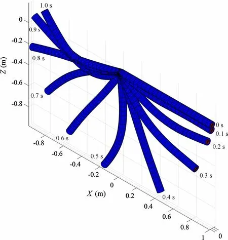
Fig. 8 Configurations of the wire
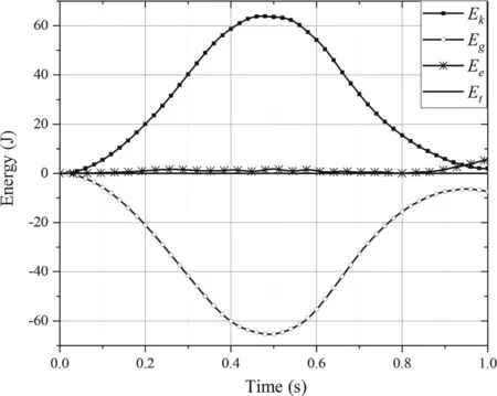
Fig. 9 Energy balance checking
6 Conclusion
In this research, a systematic algorithm for the integration over the ANCF fully parameterized beam element with smooth varying and continuous cross sections is presented.Then it is used to model the multilayer beam with a circular cross section and different material at each layer. The methods for obtaining the location of the integration points and the weight coefficients are given. Therefore, the integration of the element mass matrix and the generalized force can be performed by separation into two parts. They are the integration along the beam axis and the integration over the circular cross section. As a result, the obtained beam element is suitable for modeling the high-voltage wire. The general continuum mechanical approach can be applied to the newly obtained beam element. The formulation of the strain energy is modified to make it more accurate for describing the overall material property of the electrical wire. The integration of the axial stretching is only performed on the centerline of the element instead of the whole volume in order to negate the effect of bending stiffness. In addition, the nearly incompressible Mooney-Rivlin material model is applied to the element to describe the insulation cover for some particular type of wire. The formulation for the Jacobian matrix of the generalized elastic force with respect to the nodal coordinates is given so the implicit integrator can be used. In order to test the performance of the element, some numerical results are presented. The static problem of a circular cross-section cantilever beam with two layers is given. The calculation results obtained by the element are compared to the theoretical results. The element shows good accuracy and convergence properties. A flexible pendulum example is set up. The balance of the kinetic, elastic, potential and total energy is checked. Finally, a contact problem is tested.The configurations of the wire at different moments are compared with the results obtained from the experiment by high-speed camera. The feasibility of the element is therefore demonstrated.
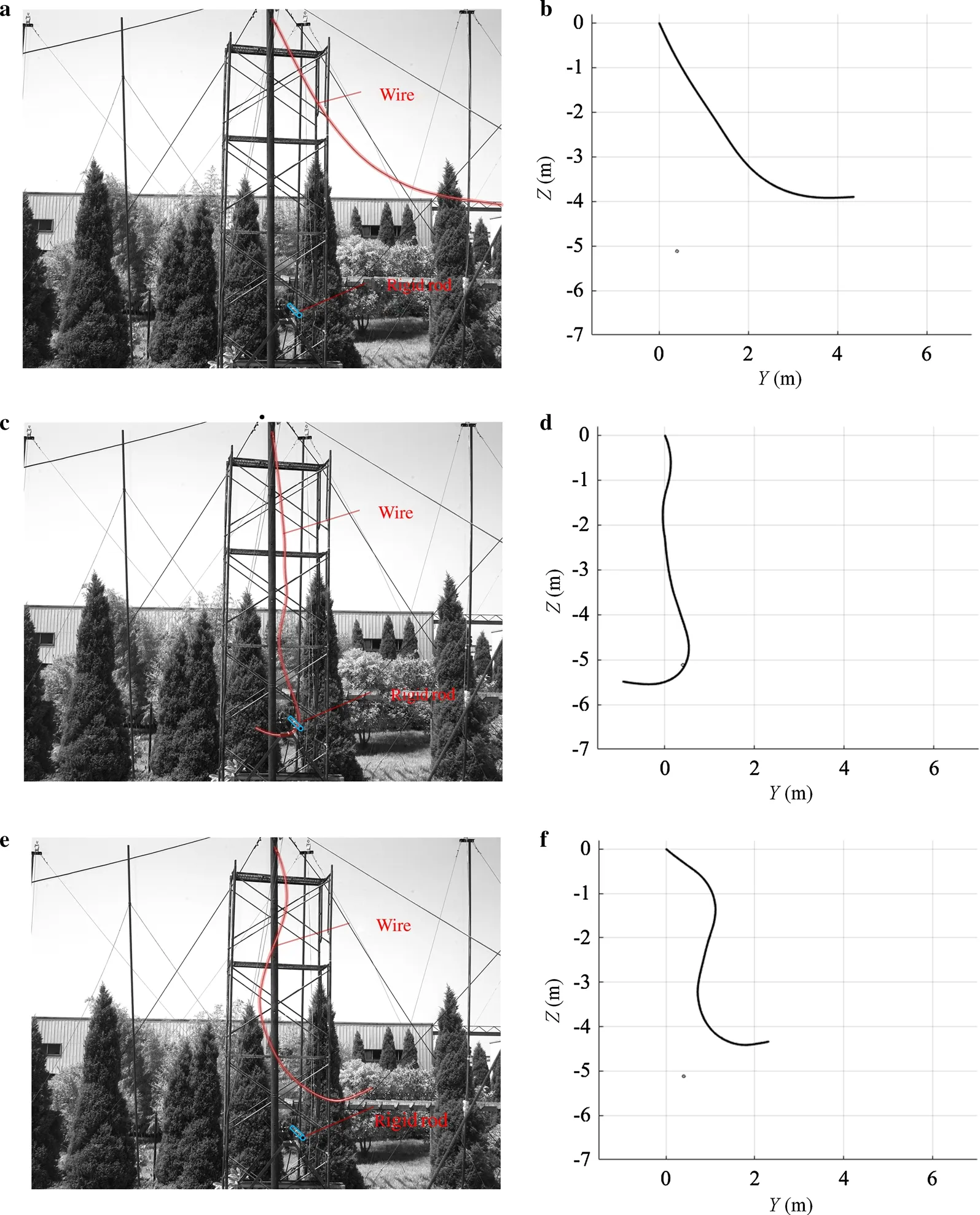
Fig. 10 Simulation and experimental result. a Wire fall. b, d, f ANCF simulation results. c Wire contact with rigid rod. e Contact end
AcknowledgementsThis work was supported by the National Natural Science Foundation of China(Grant 11802072)and the Fundamental Research Funds for the Central Universities (Grant HIT. NSRIF 2018032). The experiment was completed with the help of China Electric Power Research Institute.
Appendix
The global position vector is r=Se:
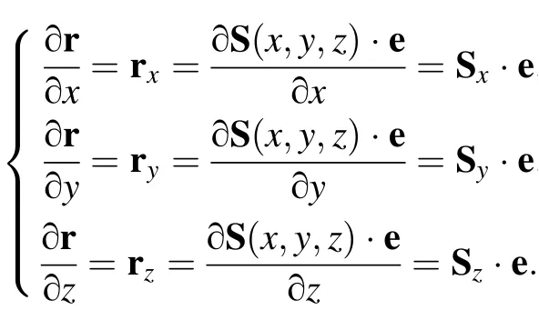
The position vector gradients are defined as
Cris the right Cauchy-Green strain tensors Cr=JTJ,
where J is the matrix of position vector gradients,which is defined as J=[rx,ry,rz]:
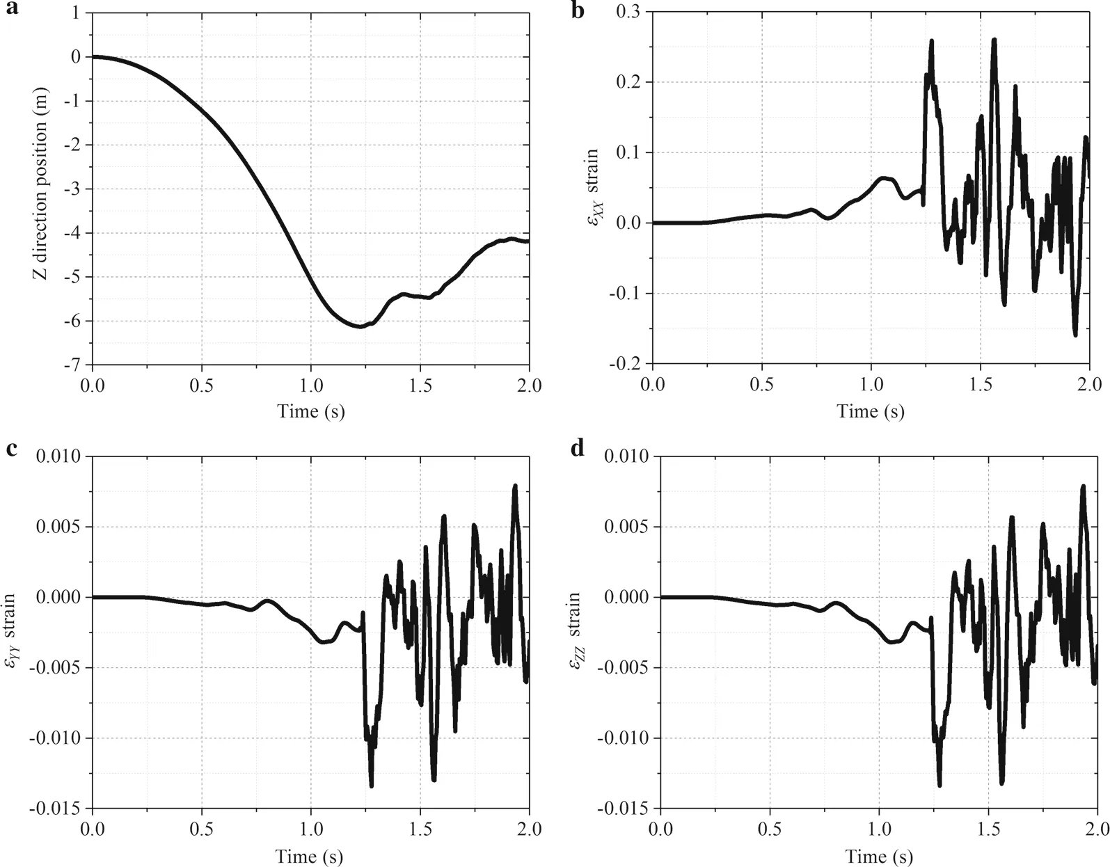
Fig. 11 Displacement and norm strain of the point first to make contact.a Displacement in the Z direction position.b Norm strain ζXX.c Norm strain ζYY. d Norm strain ζZZ

Fig. 12 Comparison of gradient vectors in two different descriptions.a Beam developed in this investigation.b Beam described in a cylindrical coordinates system
Because the right Cauchy-Green strain tensors are symmetric,one can identify six independent strain components that can be used to define the following strain vector Crv=[Cr(1,1),Cr(2,2),Cr(3,3),Cr(1,2),Cr(1,3),Cr(2,3)]T:
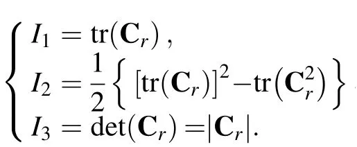
The three invariants I1, I2and I3are defined as
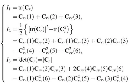
The three invariants I1, I2and I3can be written more explicitly as

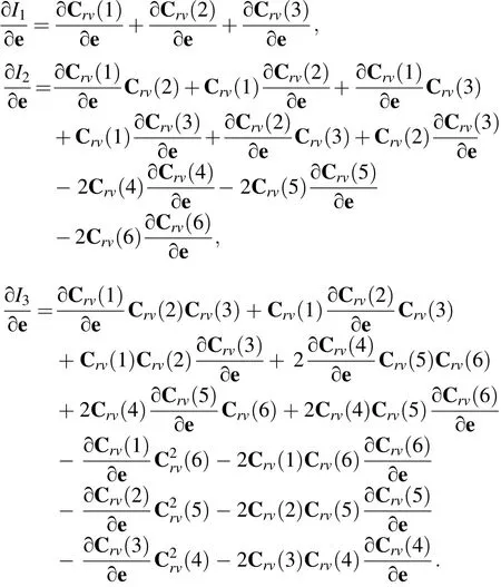
∂I1/∂e, ∂I2/∂e and ∂I3/∂e can be written as
杂志排行
Acta Mechanica Sinica的其它文章
- Geometric and material nonlinearities of sandwich beams under static loads
- Coupled thermoelastic theory and associated variational principles based on decomposition of internal energy
- Transient growth in turbulent particle-laden channel flow
- Experimental and theoretical investigation of the failure behavior of a reinforced concrete target under high-energy penetration
- Revealing the high-frequency attenuation mechanism of polyurea-matrix composites
- Efficient algorithm for 3D bimodulus structures
