Applications of multi-dimensional schemes on unstructured grids for high-accuracy heat flux prediction
2020-05-06YunboWanNianhuaWangLaipingZhangYeweiGui
Yunbo Wan · Nianhua Wang · Laiping Zhang · Yewei Gui
Abstract The simulation of hypersonic flows with fully unstructured (tetrahedral) grids has severe problems with respect to the prediction of stagnation region heating, due to the random face orientation without alignment to the bow shock. To improve the accuracy of aero-heating predictions, three multi-dimensional approaches on unstructured grids are coupled in our Reynolds averaged Navier-Stokes (RANS) solver, including multi-dimensional upwind flux reconstruction (MUP), multi-dimensional limiter (MLP-u2) and multi-dimensional gradient reconstruction (MLR). The coupled multi-dimensional RANS solver is validated by several typical verification and validation (V&V) cases, including hypersonic flows over a cylinder, a blunt biconic, and a double-ellipsoid, with commonly used prism/tetrahedral hybrid grids. Finally, the coupled multi-dimensional solver is applied to simulating the heat flux distribution over a 3D engineering configuration, i.e. a Hermes-like space shuttle model. The obtained numerical results are compared with experimental data. The predicted results demonstrate that the coupled multi-dimensional approach has a good prediction capability on aerodynamic heating over a wide range of complex engineering configurations.
Keywords Heat-flux prediction · Unstructured grid · Multi-dimensional gradient reconstruction · Multi-dimensional limiter · Multi-dimensional upwind scheme
1 Introduction
New concepts for hypersonic vehicles are proposed continuously in recent years, and in each case accurate prediction of the aerothermodynamics environment is critical for the design of the thermo-protection system (TPS). Appropriate TPS design is essential for the survival of the payload, which may include extremely expensive scientific equipment and/or life in the form of astronauts. Therefore, the accuracy of aero-heating prediction has attracted much attention. On the other hand, due to the complex geometry of modern lifting body hypersonic vehicles such as the wave-rider configurations, generating high-quality structured grids is extremely laborious and requires high user expertise; so, it is hard to meet the need for engineering applications. In order to shorten the task cycle, it is necessary to develop numerical methods for accurate predictions on the aerothermodynamic environment with unstructured/hybrid grids, which provide good adaptability for complex configurations [1, 2].
As is well known, unstructured/hybrid grid techniques have demonstrated success in aerodynamic performance prediction over complex configurations [1]. However, the aero-heating predictions using unstructured grids are much poorer compared with those on structured grids, especially in the hypersonic stagnation region [3]. The prediction accuracy of high Reynolds number simulations has been found to be very sensitive to the choice of algorithms with regard to high aspect ratio and poorly aligned tetrahedral cells, compared with those predicted by structured grids aligned to the bow shock. Particularly, the prediction of the post-shock velocities and entropy, which connect to the outer edge of the boundary layer, affects the quality of the heat transfer predictions significantly [3]. This phenomenon was further investigated by Nompelis et al. [4], who studied various configurations with unstructured grids to compare hypersonic heat flux predictions. They found that the prediction accuracy is very sensitive to the grid design due to the extremely large gradients near the shock, and that poorly shock-aligned tetrahedral cells will introduce pronounced errors in the subsonic entropy layer behind the bow shock. Candler et al. [5] also investigated the use of tetrahedral, prismatic, and hybrid hexahedral-prismatic-tetrahedral grids for the accurate prediction of aero-heating at hypersonic conditions. They were very skeptical about the utility of tetrahedral grids for accurate hypersonic aero-heating predictions and advocated the use of unstructured hexahedral grids in the stagnation region. Similarly, Mazaheri and Kleb [6] found that, even on structured grids, the perturbations of structured grid points could produce asymmetric heat transfer rates for symmetric geometries. Moreover, non-smooth grids near the shock wave, as well as within the boundary layer, can produce large local errors in heat flux but without significant influence on surface pressures.
Based on the results of simulations with various configurations, it was shown that the lack of alignment of tetrahedral cells to the shock will result in the injection of spurious momentum into the flow field and poor prediction of the post-shock velocities [3-6]. Refining the tetrahedral cells with adaptation techniques in the regions of shock waves does improve the solution significantly, which implies that the quality of the predicted solution depends both on the orientation of the cell interfaces to flow features, and on the size of each control volume [7]. In order to align the tetrahedral cells with the captured bow shock, an unstructured grid shock fitting approach was recently proposed [8] to improve the aero-heating prediction accuracy. However, in realistic engineering applications over complex configurations with hybrid grids, the body-fitted prismatic and/or unstructured hexahedral grids are usually adopted in the boundary layer, while random face orientation tetrahedral cells are utilized in the off-body field in which the position of shock waves is not known in advance. Therefore, it is necessary to develop appropriate numerical methods on commonly used hybrid grids to improve the accuracy of aero-heating predictions.
Computation on unstructured grids is a truly multi-dimensional problem, due to the random interface orientation of unstructured grids. So we need truly multi-dimensional numerical algorithms to capture the multi-dimensional properties and produce better results on unstructured grids. In the series of works by Gnoffo et al. [9-12], multi-dimensional inviscid flux reconstruction was introduced to improve the aero-heating predictions. This approach does produce better results than the conventional “quasi-one-dimensional” flux scheme. However, the results over complex geometry (such as STS-2) [11] were reported only on tetrahedral grids converted from hexahedral grids. No more complicated examples were reported on fully unstructured/hybrid grids.
There are several multi-dimensional approaches in references, including multi-dimensional inviscid flux reconstruction [9, 10, 13-15], multi-dimensional limiters [16-18], and multi-dimensional gradient reconstructions [19, 20]. In our previous works [21-23], the effects of three types of multi-dimensional approaches, including the multidimensional rotated upwind flux scheme [15], the MLP-u2 multi-dimensional limiter [16] and the MLR multi-dimensional gradient reconstruction approach [20], have been investigated one-by-one, and they do improve the accuracy of aero-heating results in typical hypersonic cases of 2D and/or 3D cylinders [3, 4]. So in this study, as a natural next approach, these three types of multi-dimensional approaches are coupled to further improve the heat flux prediction over engineering configurations. Some typical verification and validation (V&V) cases, including hypersonic flows over a cylinder, a blunt biconic, and a double-ellipsoid, are tested with commonly used prism/tetrahedral hybrid grids to validate the heat flux prediction capability of the coupled multi-dimensional approach. The coupled multi-dimensional solver is then applied to aero-heating prediction over a 3D engineering configuration, i.e. a Hermes-like space shuttle model. The results are compared with experimental data and some numerical results by our structured solver. The consistent results suggest that the present coupled multi-dimensional approach can predict aerodynamic heating accurately on unstructured/hybrid grids over complex configurations in engineering applications.
2 Governing equations and multi‑dimensional schemes on unstructured grids
2.1 Governing equations and second-order cell-centered finite volume method
In this work, the NS equations are solved based on the thermal ideal gas model. The integral form can be written as follows:

where Q is the vector of conservative variables, Fiand Fvare inviscid and viscous flux, respectively, Ω is the control volume, and ∂Ω is the outer boundary of the control volume.
A structured/unstructured coupled computational fluid dynamics (CFD) solver, HyperFLOW, developed by the authors’ group in our previous work [24, 25] is adopted here to solve the governing equations. In this work, only the unstructured solver in HyperFLOW is used. The well-known second-order cell-centered finite volume method is employed for spatial discretization with normal gradient modification on the cell interface for the viscous term [26], and the lower-upper symmetric Gauss-Seidel (LUSGS) scheme for the temporal discretization. More details can be found in Refs. [24-26]. In this work, only the laminar cases are considered, so we do not consider any turbulence model in the simulations. The applications for turbulent flows will be carried out in our future work.
Reconstruction on the left and right sides of the grid interface is a key step for the flux calculation. We will discuss it in the following sub-sections in detail. The unified linear reconstruction method used in this paper, as shown in Fig. 1, is given by:

where U is the vector of the primitive variables. The subscript I refers to the target cell I, the subscripts L and R stand for the left and right sides of the interface, respectively. ∇U represents the gradient of the flow quantity. The vector Δr points from the cell-centroid to the interface midpoint, and Φ denotes a limiter function.
2.2 Multi-dimensional gradient reconstruction method
At present, the widely used reconstruction methods are Gauss-Green and least-square methods on unstructured meshes. These two methods have several forms such as the cell-based Gauss-Green method (GG-Cell method), node based Gauss-Green method (GG-Node method), weighted least squared method (WLSQ method), and a hybrid method of Green-Gauss and least squares (GLSQ method). Our previous study has shown that these methods present poor performance on heat flux calculations on commonly used hybrid grids [22]. Here, we apply the multi-dimensional linear reconstruction (MLR) method introduced in Ref. [20].
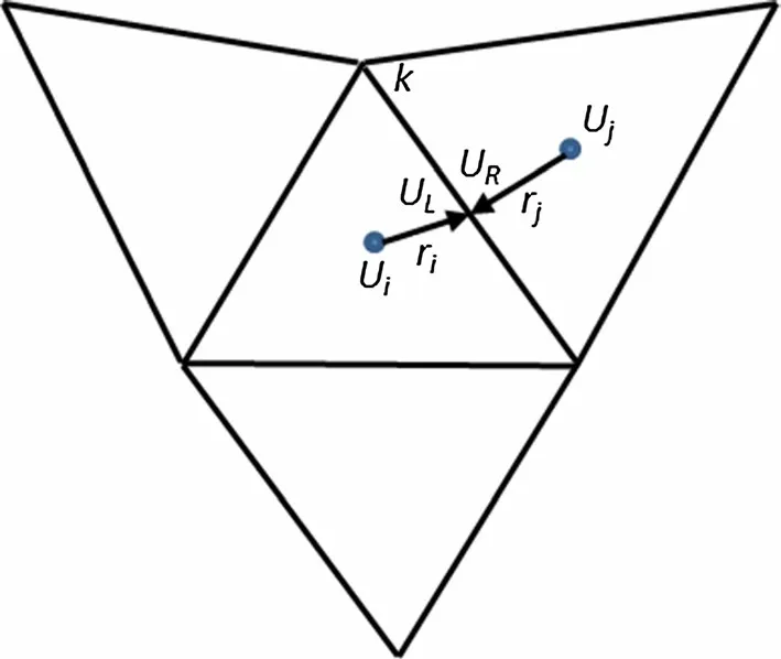
Fig. 1 Reconstruction of interface variables
The simple linear average can hardly guarantee accuracy in practical simulations, especially in the three-dimensional simulations with strong cross-flows. In order to reduce the error caused by the gradient calculation, the multi-dimensional linear reconstruction method was first proposed by Holmes [19], and then Kim et al. [20] improved it (here referred to as the MLR method). The quasi-Laplacian method is adopted in the multi-dimensional gradient reconstruction to calculate the weight factors. In 2D cases, for example, the weight factors wJare supposed to satisfy the condition of zero pseudo-Laplacian:

where (xc,J, yc,J) are the coordinates of cell center J around vertex A, and (xA, yA) denote the coordinates of a cell node. The weight factor wJcan be written as follows:

The weight factors wJare determined by solving an optimization problem in which the cost-function to be minimized is defined as:

where rJis the distance from the center of cell J to the vertex A. We can obtain wJby solving Eqs. (3) and (5) through the following formulation:

in which:
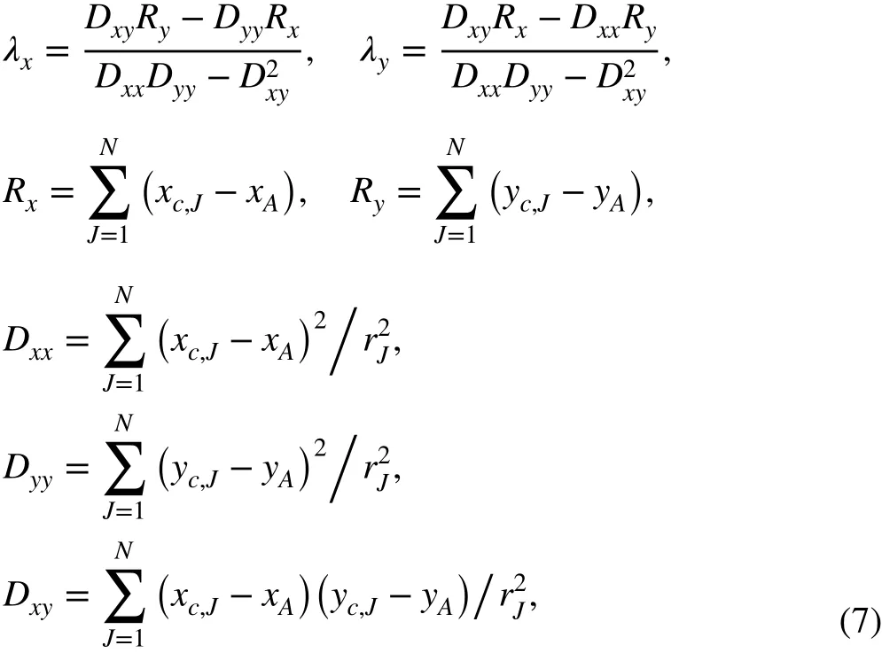
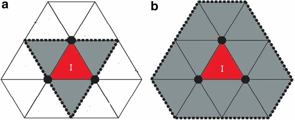
Fig. 2 Grid stencils for a Venkatakrishnan limiter and b MLP-u2 limiter
2.3 Multi-dimensional limiters
The Venkatakrishnan limiter [27] and The Barth limiter [28] are widely used on unstructured grids. However, it is hard for them to predict the heat-flux accurately on unstructured grids. To overcome this difficulty, Kim et al. [16] proposed a robust, accurate, and efficient MLP-u2 multidimensional limiter based on the Venkatakrishnan limiter. The MLP-u2 limiter can suppress multi-dimensional oscillations and accurately capture flow details, including strong discontinuities on unstructured grids [21]. The differences between the MLP-u2 limiter and the baseline Venkatakrishnan limiter are the stencil involved in limiter construction and the maximum principle, as shown in Fig. 2. It can be seen that the MLP-u2 limiter uses a wider grid stencil and contains more flow information. Moreover, Kim et al. [20] have proved that the MLP-u2 limiter satisfies the maximum principle and guarantees the monotonicity of the results. Above all, the MLP limiter is less sensitive to local mesh distributions with more accurate simulations for flow physics.
The MLP-u2 limiter can be generally formulated as follows:

where rvJ,Iis the vector from the centroid of the cell I to its vertex vJ. rvJ,Iis the ratio of the maximal allowable variation among the vertexes vJof cell I:

The format of Φ is the same as that of the Venkatakrishnan limiter, which can be written as follows:

where

in which K is an empirical parameter, ds the distance between the two cell centers, lrefthe reference length associated with the entire mesh (usually taken as the cubic root of the entire computational mesh volume), and pIthe pressure of the cell I. More details can refer to Ref. [21].
2.4 Multi-dimensional upwind scheme for inviscid flux calculation
Multi-dimensional upwind schemes (MUP) have received increasing attention in recent years. Roe [29] has summarized the multi-dimensional upwind methods in detail. The rotated upwind scheme [15] has become popular because it can capture shock waves robustly and has a simple format. Based on widely-used second-order methods, the rotated upwind scheme gains great improvement in terms of robustness and efficiency.
As shown in Fig. 3, the multi-dimensional upwind scheme can be completed by the following three steps.
1. Select the upwind direction w1, such as the gradient direction of density or pressure, etc.
2. Calculate the flux in the upwind direction w1and its vertical direction w2.
3. Calculate the flux in the direction normal to the surface.
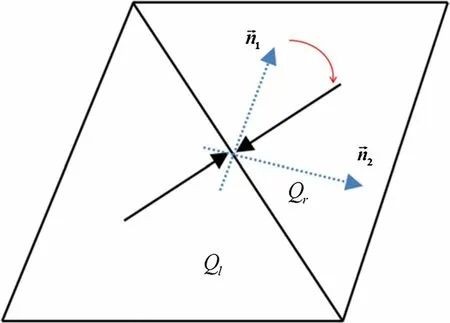
Fig. 3 Sketch of the multi-dimensional upwind scheme
The traditional van Leer scheme [30] is used here as the baseline scheme for calculating the flux in each direction. Actually, some other flux schemes, e.g., the well-known Roe scheme, can be adopted here. But for hypersonic cases, the carbuncle phenomenon will occur if an improper entropy modification is adopted. In order to exclude the effect of entropy modification, we choose the van Leer flux splitting scheme here, even though it is relatively more dissipative than the Roe scheme. When the grids in the boundary layer are fine enough, the numerical dissipation will not affect the final results. The key to successful application of the multidimensional upwind scheme is the selection of the upwind direction w1. In this work, the upwind direction is chosen as Eq. (12), based on the velocity difference vector direction:

where Δq=(uR-uL,vR-vL) (for the 2D case), w refers to the vector normal to the interface, ε is a small number and is set to 10-8in this work.
Since the changing direction w1in the multi-dimensional upwind scheme may lead to a low convergence rate, the upwind direction is fixed after specified time steps (10,000 time steps in this paper) to improve the convergence feature.
3 Applications of the coupled multi‑dimensional approach
3.1 2D and 3D cylinders
1. 2D cylinder
A 2D cylinder is chosen first to validate the capability of the coupled multi-dimensional approach (marked as “CoupledFV” in the following context). The radius of the cylinder is 1 m, and the computational conditions are M∞(Mach number of incoming flow) = 8.03, T∞(temperature of incoming flow) = 124.94 K, Tw(temperature of the solid wall) = 294.44 K, and Re (Reynolds number of incoming flow) = 1.835 × 10⁵in Ref. [31]. The computational grid is a commonly used hybrid grid shown in Fig. 4. Quadrilateral cells are employed in the boundary layer and triangles in the off-body domain. To capture the shock waves accurately, the triangles in the off-body domain are properly refined. Five schemes are adopted here to do comparison, including the multi-dimensional linear reconstruction method (marked as “MLR”), the MLP-u2 multi-dimensional limiter (marked as “MLP_u2”), the multi-dimensional upwind schemes (marked as “MUP”), the coupled multi-dimensional approach (marked as “Coupled FV”) and the original second-order FV scheme (marked as “NormalFV”). The details of these schemes are listed in Table 1. The CPU times of each iteration time step for these five schemes are also listed in Table 1, which are tested using a single core on a personal computer with Intel CPU 4.0 GHz under the Windows Operating System. We can see that the computational cost of the multidimensional upwind scheme is over 7 times of that of the normal finite volume method, due to the rotated upwind operator, and two other multi-dimensional schemes (MLR and MLP_u2) are slightly slower than NormalFV. Thus, the computational cost of the coupled multi-dimensional scheme is the same order as that of MUP, much more expensive than MLR and MLP_u2.
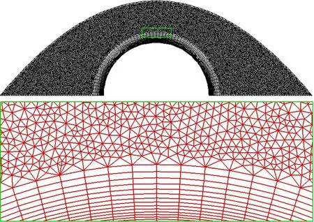
Fig. 4 Commonly used hybrid grids for the 2D cylinder (quadrilateral cells in the boundary layer and triangles in the off-body region)
The pressure contours in Fig. 5 show that these multidimensional schemes, as well as the scheme without introducing any multi-dimensional approach, are all able to capture the shock wave and the internal structure of the flow field. Figure 6 depicts the Mach number contours predicted by the coupled multi-dimensional approach. The other methods provide very similar results, so we do not show them here. The surface pressure coefficient distributions calculated by these methods are shown in Fig. 7. They are smooth and almost symmetric, and agree well with the experimental data [31], even though there is a slight deviation for the “NormalFV” method in the stagnation region. However, there are significant differences in heat flux distributions on the solid wall, as shown in Fig. 8. The “NormalFV” method gives an asymmetric result which severely differs from the experimental data [31]. The three multi-dimensional approaches (MUP, MLR, MLP_u2) can greatly improve the result. Moreover, the coupled multi-dimensional approach provides the best result, which agrees very well with the experimental data [31]. Figure 9 shows the convergence history of these five methods. We can see that the coupled multi-dimensional approach (“CoupledFV”) performs best with regard to convergence. The reason the multi-dimensional approaches can improve the aero-heating prediction accuracy is that they can effectively suppress the oscillation of velocity after the bow shock, which has been discussed in Refs. [21-23].

Table 1 Five numerical schemes and CPU times for each iteration time step
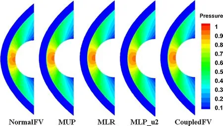
Fig. 5 Pressure contours over the 2D cylinder by the five methods
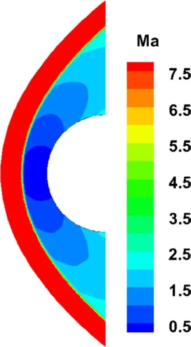
Fig. 6 Mach number contours over the 2D cylinder by the coupled multi-dimensional approach (CoupledFV)
2. Three-dimensional cylinder
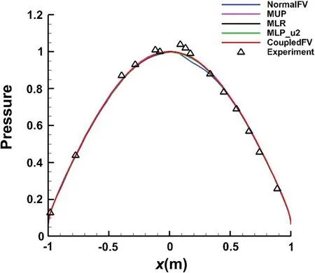
Fig. 7 Surface pressure coefficient distribution by the five methods and compared with the experimental data
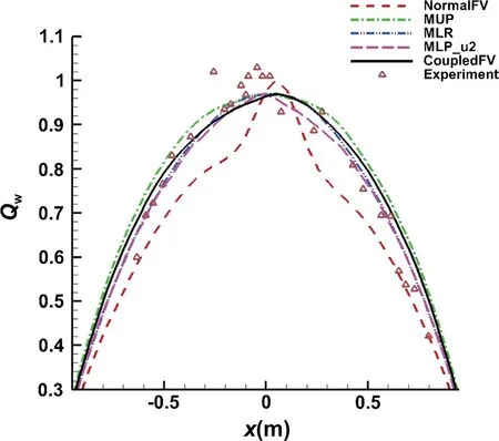
Fig. 8 Heat flux distribution over the 2D cylinder by the five methods and compared with experimental data
In order to further test the performance of the coupled multi-dimensional approach, we consider a 3D cylinder which is extended from the above 2D cylinder in the spanwise direction. The incoming flow conditions are the same as those in the 2D case. The computational hybrid grids consist of hexahedral mesh in the boundary region and isotropic tetrahedral mesh in the off-body region, as shown in Fig. 10. With tetrahedral grids in the off-body region, identity is hard to maintain in the span-wise direction, due to the random orientation of interfaces, so it is difficult to get consistent computational results for the 3D case. Figures 11 and 12 show the contours of pressure and Mach number on four cross-sections and on a solid wall by the coupled multi-dimensional approach. Due to the high resolution of the shock wave and flow field, the flow structures on the sections are consistent with each other, and the carbuncle phenomenon does not appear in the stagnation region.
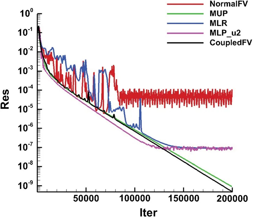
Fig. 9 Convergence history for the 2D cylinder case by the five methods
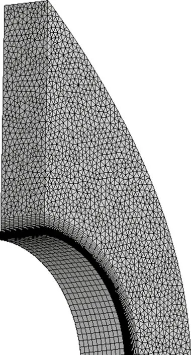
Fig. 10 Hybrid grids over the 3D cylinder (hexahedral in the boundary layer and isotropic tetrahedral grids in the off-body region)
The wall pressure coefficient distributions on the four sections are nearly coincident with each other and symmetric, as plotted in Fig. 13. The results agree well with the experimental data [31]. For the pressure prediction, the coupled multi-dimensional approach does not perform better than the normal one. However, the heat flux prediction
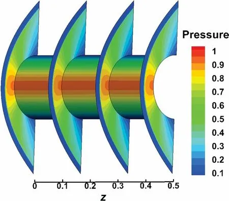
Fig. 11 Pressure contours on four cross-sections and solid wall by the coupled multi-dimensional approach (CoupleFV)
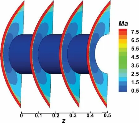
Fig. 12 Mach contours on four cross-sections and solid wall by the coupled multi-dimensional approach (CoupledFV)
is significantly improved by the coupled multi-dimensional approach, as shown in Figs. 14 and 15. Here we do not show the results by MUP, MLR, and MLP_u2, otherwise, there would be too many lines in Fig. 15. We can see from Fig. 14 that the heat flux is fully asymmetric by the “NormalFV” approach, but the coupled multi-dimensional method (“CoupledFV”) gives much better results. The heat flux distributions on the four cross-sections are plotted in Fig. 15, and the quantitative results coincide with the qualitative comparison in Fig. 14.
3.2 Blunt biconic
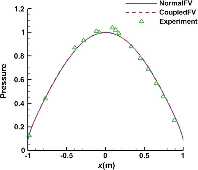
Fig. 13 Comparison of pressure distributions on four cross-sections and experimental data
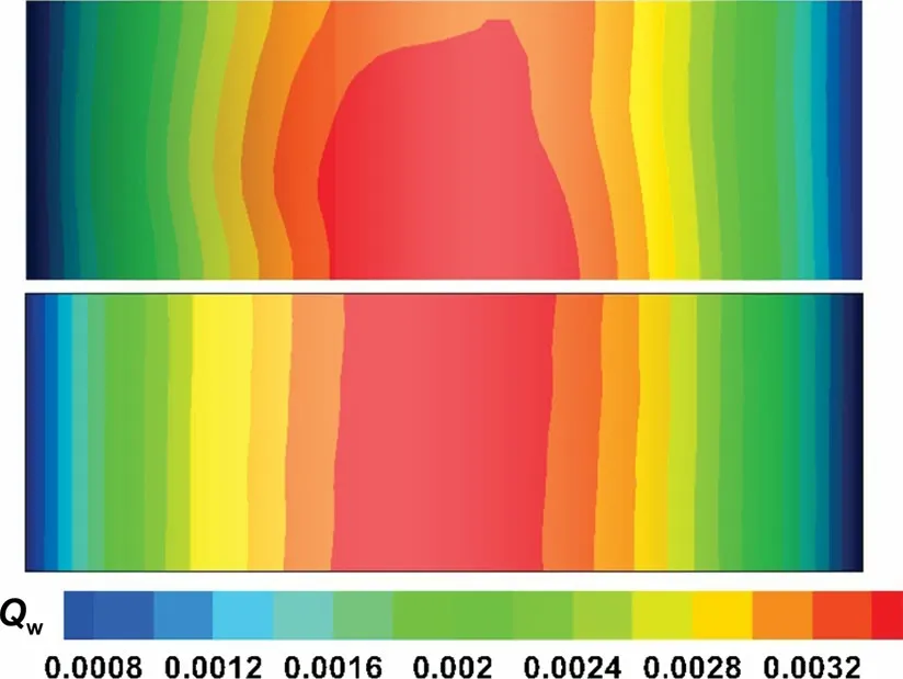
Fig. 14 Heat flux distribution on the solid wall (upper: NormalFV; lower: CoupledFV)
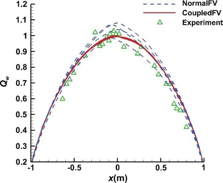
Fig. 15 Comparison of heat flux distributions on four cross-sections and experimental data
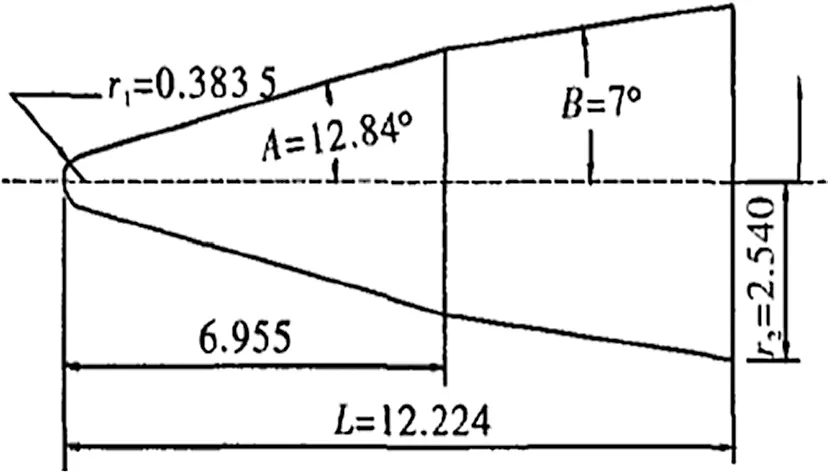
Fig. 16 Geometry of the blunt biconic model
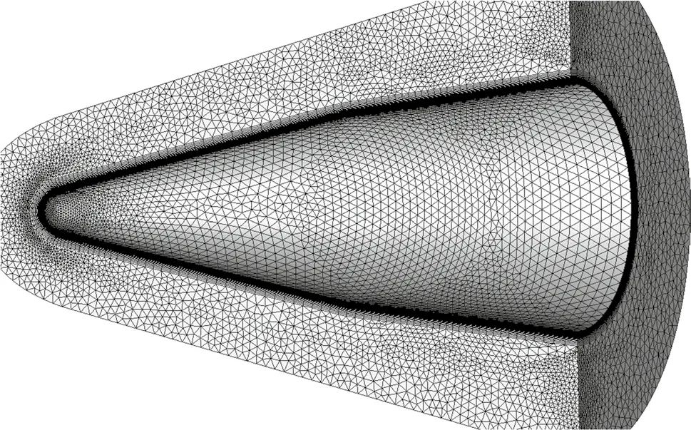
Fig. 17 Hybrid grids over biconic configuration
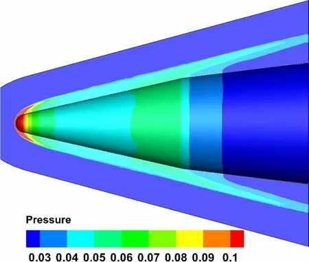
Fig. 18 Pressure contours on the symmetric plane and solid wall by CoupledFV
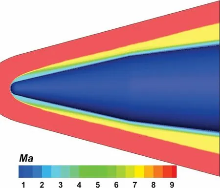
Fig. 19 Mach number contours on the symmetric plane and solid wall by CoupledFV
The second test is a typical validation case of hypersonic flow over a blunt biconic. The detailed dimensions of the biconic model are shown in Fig. 16. The calculation grids consist of prisms in the boundary layer region and isotropic tetrahedral grids in the off-body region, as shown in Fig. 17. The computational conditions are M∞= 9.86, Re= 1.896 × 10⁶m-1, T∞= 48.8 K, Tw= 300 K, and angle of attack α = 0°. The pressure and Mach number contours on the symmetric plane and solid wall show that the coupled multi-dimensional approach can accurately capture the bow shock in Figs. 18 and 19. The results by other methods are almost identical, so we do not show them here. In Fig. 20, the heat flux contours on the solid wall are shown by the mentioned five approaches. The coupled multi-dimensional approach gives the best results without any unreasonable disturbance (Fig. 20e), while there are obvious non-physical disturbances for the “NormalFV” method (Fig. 20a). The three separate multi-dimensional methods, i.e. MLP_u2, MLP, MUP, can improve the heat flux distributions, however, their results in Fig. 20b-d are still slightly worse than those by the coupled multi-dimensional approach. The heat flux distribution on the solid wall is plotted in Fig. 21, which agrees well with the experimental results [32]. The heat flux of the stagnation point measured in the wind-tunnel experiment is 337 kW/m2, and the value calculated by the coupled multidimensional approach is 348 kW/m2. The difference is in a reasonable error range. The streamlines over the blunt biconic configuration are shown in Fig. 22, and no flow separation is observed due to the low angle of attack.standard cases for studying hypersonic reentry problems.
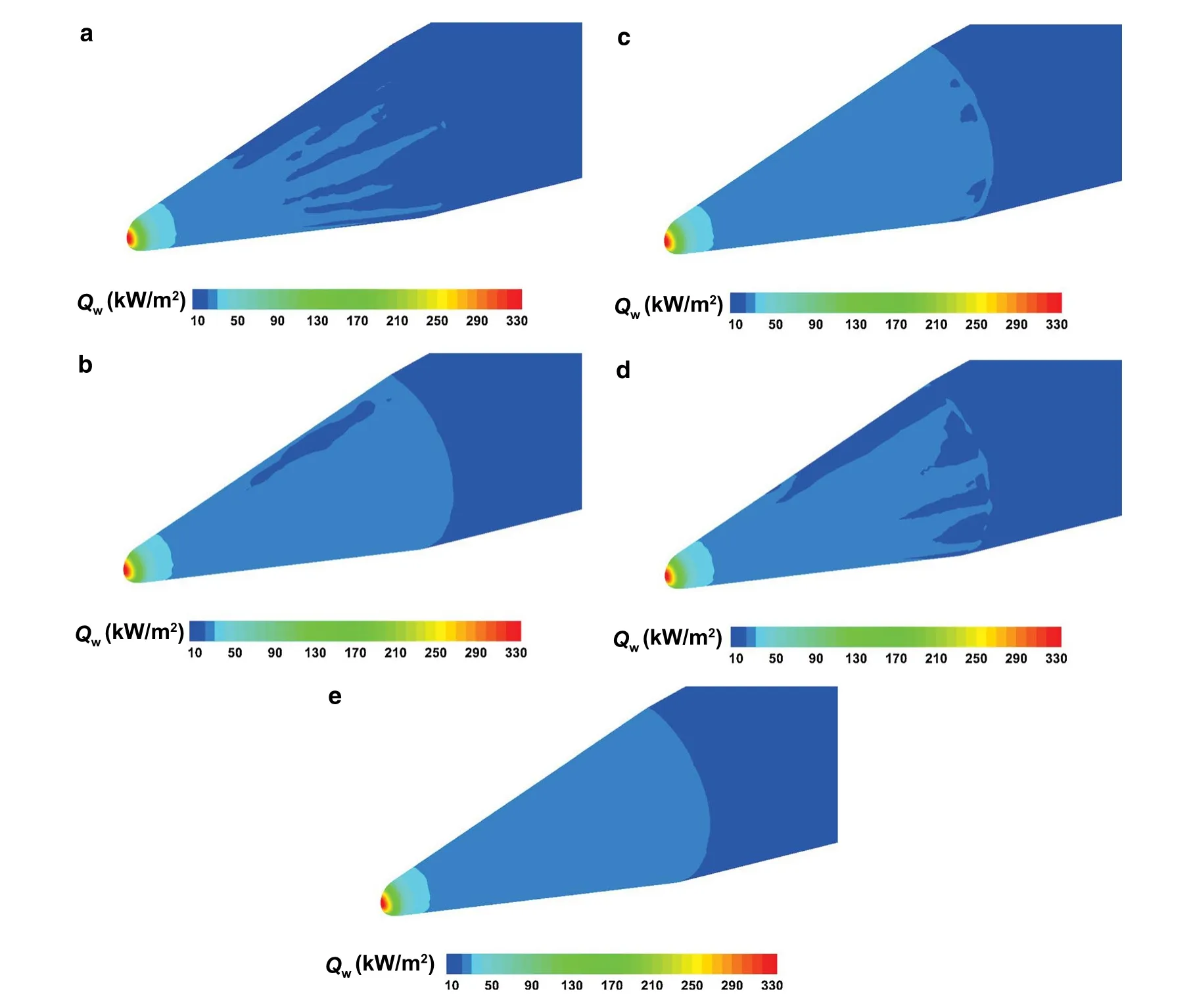
Fig. 20 Heat flux contours on the solid wall of the blunt biconic by the five approaches. a NormalFV; b MLP_u2; c MLR; d MUP; e CoupledFV
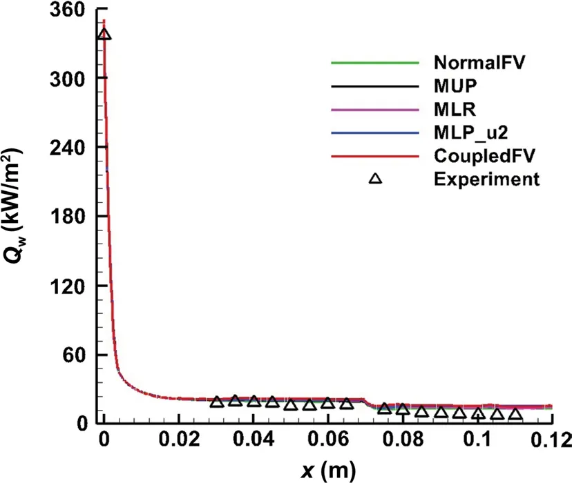
Fig. 21 Comparison of heat flux distribution on the solid wall by the five methods and experimental data

Fig. 22 Streamlines on symmetry plane and solid wall by the coupled multi-dimensional approach (CoupledFV)
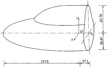
Fig. 23 Model geometry of the double ellipsoid configuration
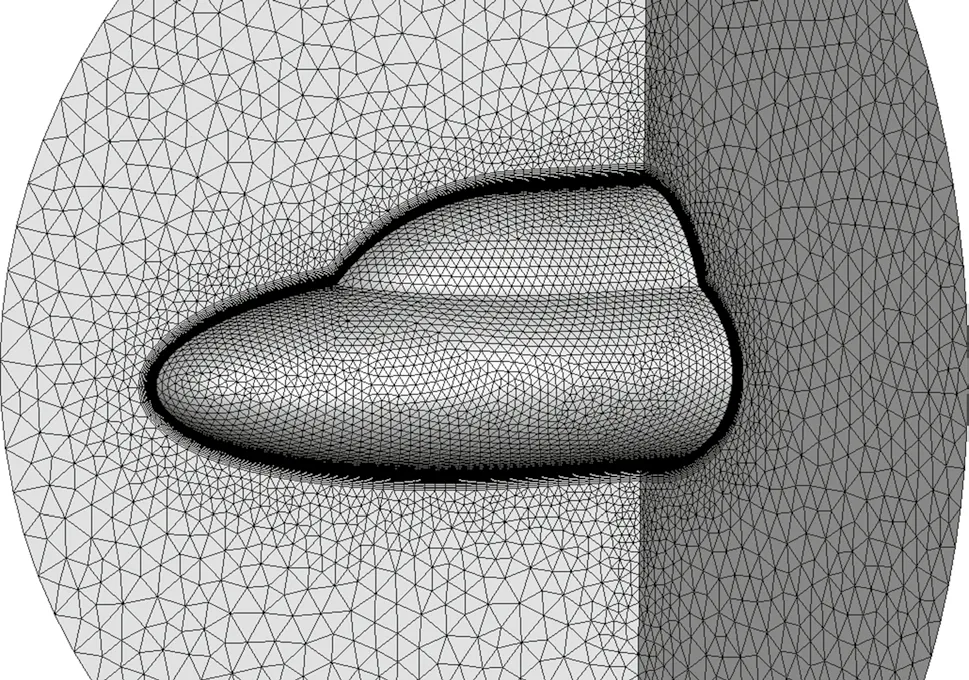
Fig. 24 Computational grid over the double ellipsoid configuration
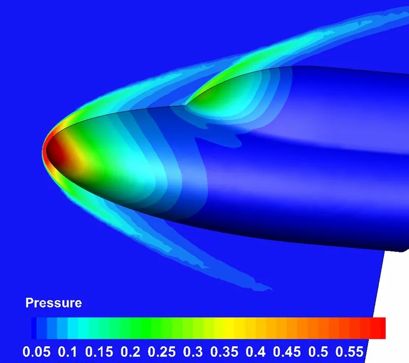
Fig. 25 Pressure contours on the symmetric plane and solid wall (α = 0°) by CoupledFV
The geometry and the main dimensions of the double ellipsoid are shown in Fig. 23. The geometry can be described as follows:
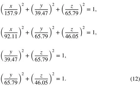
3.3 Double ellipsoid
The third case is a hypersonic flow over a double-ellipsoid configuration. The double ellipsoid configuration is one of the
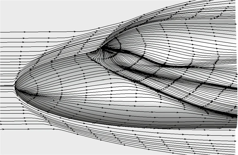
Fig. 26 Streamlines on the symmetric plane and solid wall (α = 0°) by CoupledFV
The incoming flow conditions are M∞= 10.02, Re = 2.2 × 10⁶m-1, the total pressure P0= 6.9 MPa, the total temperature T0= 1457 K, Tw= 300 K, and angles of attack α = 0°, 10°, 20°. The computational grid consists of prisms in the boundary layer region and isotropic tetrahedral grids in the off-body region (Fig. 24).
The pressure contours on the symmetric plane and solid wall at α = 0° are shown in Fig. 25, in which the bow shock and the shock ahead of the second ellipsoid are observed clearly. The streamlines in Fig. 26 indicate that multi-dimensional schemes can accurately simulate the flow separation structures. At the other two angles of attack, the flow structures are similar to those of α = 0°, so we do not show them again. Figure 27 shows the heat flux contours on the solid wall at α = 0° by the five approaches. The coupled multidimensional approach presents the best results in Fig. 27e, although the three separate multi-dimensional approaches also improve the predictions, as shown in Fig. 27b-d.
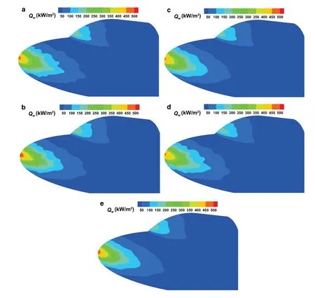
Fig. 27 Heat flux contours on the solid wall of the double-ellipsoid configuration (α = 0°). a NormalFV; b MLP_u2; c MLR; d MUP; e CoupledFV
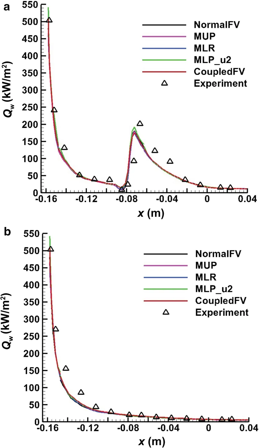
Fig. 28 Comparison of heat flux distributions on the symmetric lines of the double-ellipsoid configuration (α = 0°) by the five methods and experimental data. a Upper symmetric line; b lower symmetric line
Figure 28 gives the heat flux distributions on the upper and lower symmetric lines of the solid wall. All the results by the five methods and the experimental data [33] are shown in Fig. 28. Note that, there are only slight differences between the numerical results due to the high peak at the stagnation point, and they all agree well with the experimental data [33]. The heat flux distribution on the upper symmetric line in Fig. 28a indicates the effect of flow separation ahead of the second ellipsoid in Fig. 26. For the coupled multi-dimensional approach, the results of heat flux contours on the solid wall at α = 10° and α = 20° are plotted in Fig. 29, while the heat flux distributions on the upper and lower symmetric lines are displayed in Fig. 30. The experimental data [33] are also shown in Fig. 30. Once again, the numerical results agree well with the experimental data. Regarding the comparison between the coupled approach and the other four approaches, the behavior is very similar to that of the α = 0° case.
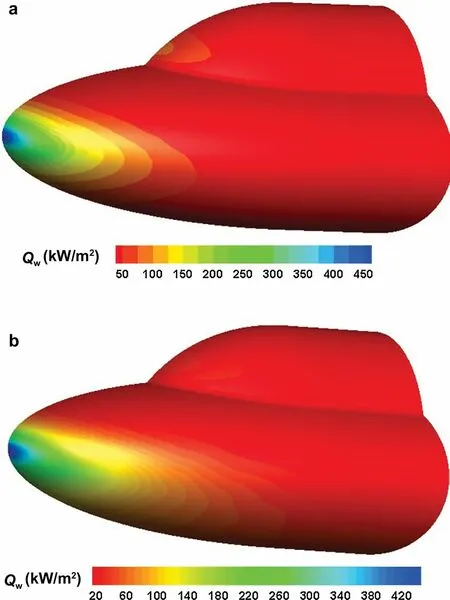
Fig. 29 Heat flux contours on the solid wall by CoupledFV (a α = 10°; b α = 20°)
3.4 Space shuttle
Finally, we apply the coupled multi-dimensional approach to a realistic space shuttle configuration. The aerodynamic layout of the space shuttle model combines the characteristics of French HERMES and Japanese HOPE. It has detailed experimental data [33] and can be used to verify the calculation results of heat flux. The incoming flow conditions are M∞= 8.04, Re= 1.13 × 10⁷m-1, P0= 7.8 MPa, T0= 892 K, Tw= 300 K, and α = 10°. The computational grid consists of prisms in the boundary layer region and anisotropic and isotropic tetrahedral grids in the off-body region, as shown in Fig. 31. Here, only the results of the coupled multi-dimensional approach are presented. The pressure contours on the symmetry plane and solid wall in Fig. 32 show a well-captured shock ahead of the model nose. Figure 33 shows how the smooth surface heat flux contours, as well as the high heat flux regions, cover the nose and the leading edge of the wing. The heat flux distributions on the upper and lower symmetric lines in Fig. 34 agree well with the experimental data [33]. In Fig. 34, we also show the results by our structured solver [34] on a structured grid in our institute, and they agree well with each other. The numerical results demonstrate the capability of the present coupled multi-dimensional approach for 3D realistic applications.
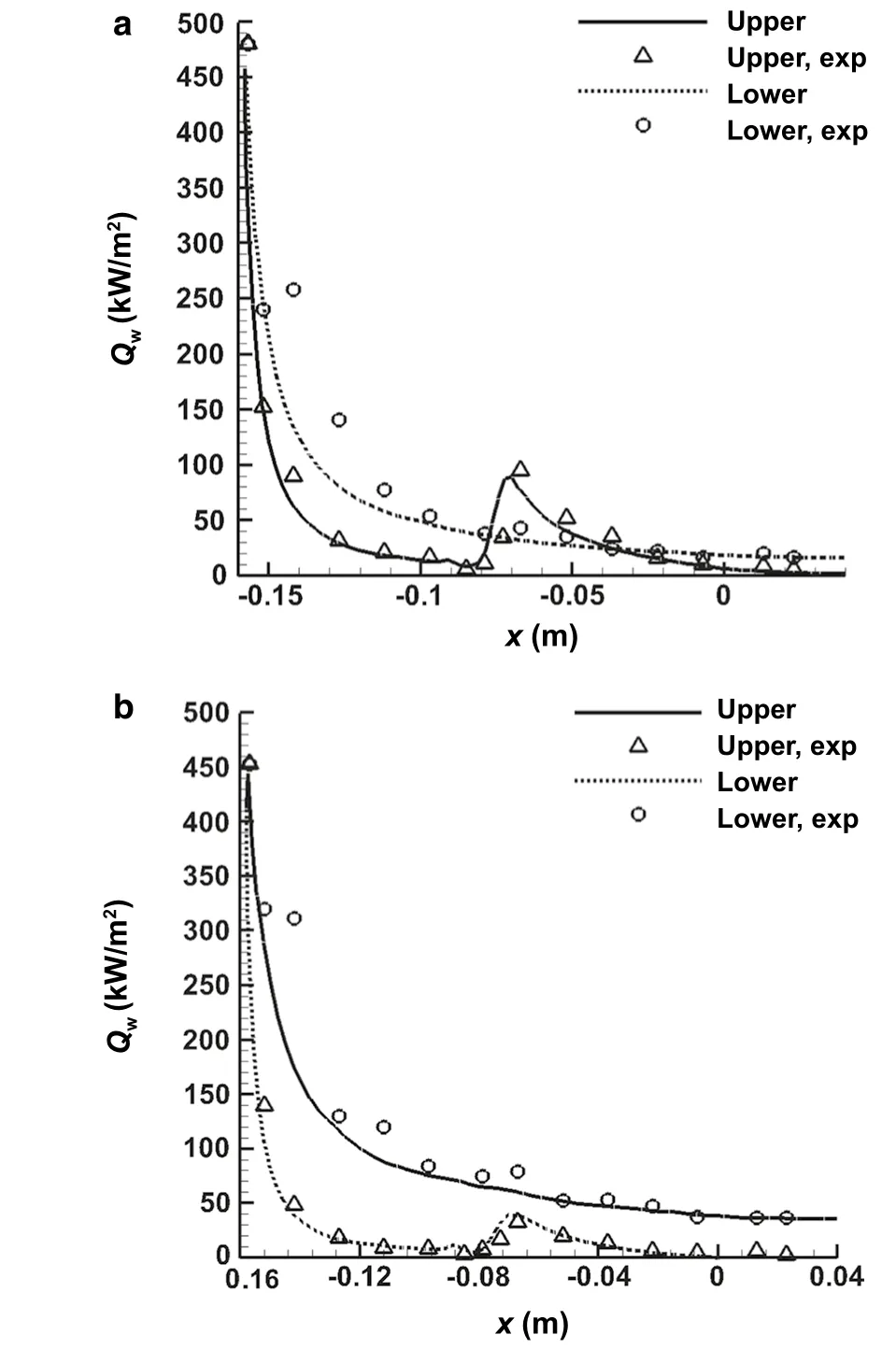
Fig. 30 Heat flux contours on the solid wall by CoupledFV (a α = 10°; b α = 20°)
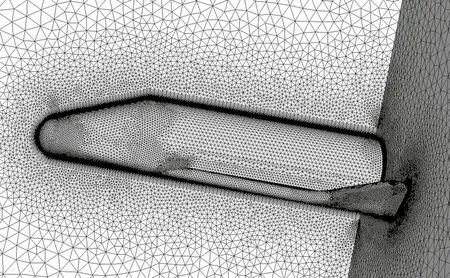
Fig. 31 Computational grids over the space shuttle model
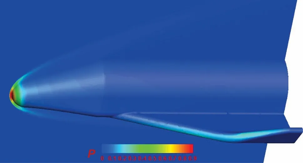
Fig. 32 Pressure contours on the symmetry plane and solid wall of the space shuttle model
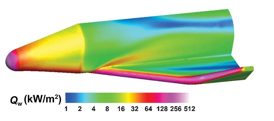
Fig. 33 Heat flux contours on the solid wall of the space shuttle model
4 Concluding remarks and future work
In order to reduce the grid sensitivity and improve the accuracy of heat flux prediction, three multi-dimensional methods are coupled into our RANS solver, including multi-dimensional upwind flux reconstruction (MUP), multi-dimensional limiter (MLP-u2) and multi-dimensional gradient reconstruction (MLR). The coupled multi-dimensional solver is validated by several typical verification and validation cases, such as hypersonic flows over a cylinder, a blunt biconic, and a double-ellipsoid configuration. The results agree well with the experimental data, which demonstrates that the coupled multi-dimensional methods can accurately simulate the flow field structures and provide heat flux prediction results on commonly used hybrid grids. We can see that the numerical results generated by the coupled multi-dimensional approach are better than those by the three separate multi-dimensional approaches, and much better than those by the traditional second-order finite-volume method. Finally, the coupled multi-dimensional approach is also applied to heat flux prediction of a 3D realistic spacecraft configuration. The consistent results demonstrate the capability of the present coupled multi-dimensional approach for highly accurate heat flux prediction on unstructured/hybrid grids in engineering applications.
However, only laminar cases are considered in this work. In the following study, we will extend this approach to the simulations of hypersonic turbulent flows over complex geometries. Also, we will consider the thermal-chemical non-equilibrium model in realistic applications. The results will be reported in the follow-up papers.
AcknowledgementsThis work was supported partially by the National Key Research & Development Program of China (2016YFB020071) and the National Natural Science Foundation of China (Grants 11532016 and 11702315).
杂志排行
Acta Mechanica Sinica的其它文章
- Geometric and material nonlinearities of sandwich beams under static loads
- Coupled thermoelastic theory and associated variational principles based on decomposition of internal energy
- Transient growth in turbulent particle-laden channel flow
- Experimental and theoretical investigation of the failure behavior of a reinforced concrete target under high-energy penetration
- Revealing the high-frequency attenuation mechanism of polyurea-matrix composites
- Efficient algorithm for 3D bimodulus structures
