Numerical Study of Trapped Solid Particles Displacement From the Elbow of an Inclined Oil Pipeline
2019-11-26DingqianDingYongtuLiangYansongLiJianfeiSunDongHanandJingLiu
Dingqian Ding ,Yongtu Liang ,Yansong Li ,Jianfei SunDong Han and Jing Liu
Abstract: The solid particle impurities generated by pipe wall corrosion might deposit at the elbow of hilly pipelines during the production shutdown of oil pipelines.These solid particle impurities will seriously affect the safety of the pipeline operation and the quality of the petroleum products.Thus,it is necessary to study the methods of removing these trapped particles from pipelines.At present,the most common way to remove these solid particle impurities is pigging oil pipelines periodically by utilizing the mechanical pigging method,while the frequent pigging operation will increase the cost and risk of pipeline operation.It is very convenient and economical to remove the accumulated particles out from the pipeline by oil stream,which can be named Hydraulic Pigging Method (HPM).However,the behavior mechanism of particle in flowing oil is still unclear.This motivates the present research on the particles flushed out by the flowing oil.A numerical model governing the trapped particles displacement from the elbow of an inclined oil pipeline is established in the Euler-Lagrangian framework.The simulation is achieved via CFD coupling with DEM.The CFD method is employed to solving the continuous phase flow,while the discrete particle phase is tracked by the DEM.The numerical model is first validated by comparison with results taken from the published literature.From the simulation results,it is observed that the oil stream,carrier phase,can only flush out the solid particles in a certain diameter range under the given operation conditions,and the particles whose diameter beyond that diameter range will cannot be removed out from the pipeline.The influence of the pipe inclined angle,the oil bulk velocity and the particle diameter on the particle migration characteristics is examined in detail.Furthermore,in order to enhance the efficiency of HPM,an Enhanced Hydraulic Pigging Method based on Multi-Physical Field Collaboration (EHPM-MPFC)is also proposed in the present work.The EHPM-MPFC is validated for having high pigging efficiency via the comparison of the migration characteristics of particles during the EHPM-MPFC and HPM process.The present results can provide the guidance to the HPM operation of products pipelines.
Keywords: Particle displacement,hydraulic pigging method,CFD-DEM coupling,multi-physical field.
1 Introduction
The transportation methods of petroleum products mainly include shipping,truck transportation,railway transportation and pipeline transportation.Pipeline transportation is the most important way of petroleum products transportation due to its advantages of low cost,high reliability,large transporting capacity and favorable environmental protection.The commissioning of these product oil pipelines is accomplished via injecting the water into pipeline to remove the air in pipelines.As result,water will accumulate at the low section along the pipeline.At the other hand,the petroleum products in the pipeline generally contain acidic substances such as sulfur or sulfide,the co-existence of water and these acidic substances will form an acidic electrolyte solution.Thus,the wall of the pipeline will undergo electrochemical corrosion in an acidic environment [Xiao,Xiao,Huang et al.(2016);Song,Yang,Yu et al.(2016)].Pipe wall corrosion generates sediments,such as iron oxide (Fe2O3or Fe3O4)is the main source of solid particle impurities in the pipelines.Besides iron oxides,there are also solid impurities such as sand and rust at the bottom of the storage tanks in the refineries.These solid impurities will also be carried into the pipeline systems in the process of injecting oil from the storage tanks to the pipelines.These solid particle impurities deposited at the elbow of the pipelines will seriously affect the safety of the pipeline running.For example,the solid particles carried by large velocity oil stream will cause the erosion of pipe wall;the attached equipment of the pipelines might be plugged;the quality of oil products might not satisfy the industry standards and so on.Therefore,studying the migration mechanisms of solid particle impurities at the low section of the hilly pipelines can lay a foundation for corrosion evaluation and monitoring the qualities of petroleum products transported in pipelines.
In order to ensure the efficiency and safety of the oil pipeline running,the pipeline should be pigged periodically.However,frequent pigging operations will increase the cost and risk of the pipeline operation.Through the experiment,Xu et al.[ Xu,Zhang,Liu et al.(2011)] proposed a method to remove the trapped water out from the multiproduct pipelines by adjusting the oil flow rate at the entrance of the pipelines.This pipeline pigging method without pigging equipment can be called Hydraulic Pigging Method (HPM).Compared to the mechanical pipeline pigging methods,HPM does not need to send the pigs into the oil pipelines,and there is no need to tracking the pigs during the oil pipelines pigging period,thus the HPM has the advantages of economic and safe pipeline pigging operation and short pigging period.Referring to the removal of the trapped water in pipelines,it is an effective measure to slow down the corrosion of pipelines by hydraulically removing the solid impurities deposited at the elbow of pipelines.
Using HPM to remove water out from the low sections along the pipelines has been actively investigated [Irikura,Maekawa,Hosokawa et al.(2014);Yang,Li,Wang et al.(2017);Xu,Cai,Ullmann et al.(2016);Song,Yang,Zhang et al.(2017);Yang,Li,Wang et al.(2018)].The aforementioned researchers employed the Volume of Fluid method (VOF)to analyze the multiphase flow characteristics in the inclined pipelines during the deposited water carried by flowing gas or oil.They obtained the flow parameters such as the phase distribution,the velocity,the pressure and the liquid holdup along the pipelines.Furthermore the effects of the velocity of the continuous phase at the pipeline entrance on the flow characteristics of deposited water lump have also been carried out.The numerical research results can provide guidance for the removal of accumulated water in oil and gas pipelines by HPM.
However,the hydraulic removal of solid particle impurity is different from that of deposited water in the pipelines.There are few related studies on the use of oil stream to carry trapped solid particles out from the pipelines.The essence of the particle impurities removal by HPM is the complex particulate flow.At present,the main methods for studying the behavior of particles in fluid flow are the Euler-Eulerian method and the Euler-Lagrangian method.The Euler-Lagrangian approach tracks each individual particle in a Lagrangian approach and fluid phase is computed in a Eulerian frame.There are many research results based on the Euler-Lagrangian method for simulating the behaviors of particles in the flow field [Parsa,Calzavarini,Toschi et al.(2012);Gustavsson,Einarsson and Mehlig (2014);Marcus,Parsa,Kramel et al.(2014);Byron,Einarsson,Gustavsson et al.(2015)],and the above literatures analyzed the orientation and distribution of particles in wall turbulence,and found that the orientation of the particles near the wall is related to the vortex structure of the flow field,the shape and the inertia of the particles.However,the flow fields involved in the aforementioned literatures are relatively simple,such as the isotropic channel turbulent flow field.The flow field in the hilly oil pipelines is more complicated.In the case of inclined pipelines,the inclination of the pipelines will interfere with the flow field in the pipeline,which makes the difference between the particle migration characteristics in the inclined pipelines and horizontal channels.It is more difficult to solve the motion of the particles in the inclined pipelines due to the more complicated flow field.To this end,this paper will carry out research on the particle migration characteristics in the hilly pipelines.
The Euler-Lagrangian method is also widely used to simulate particulate flow in the industrial area,such as natural gas and particles separation process [Wen,Cao,Yang et al.(2012);Wen,Yang,Walther et al.(2016);Yang and Wen (2017);Yang,Wang and Wen (2017)].In the above research,the authors used the Discrete Particle Method (DPM)to calculate the natural gas and particles separation characteristics in the supersonic swirling separator.Their results demonstrated that the DPM was accurate and stable enough to evaluate the dehydration characteristics of the supersonic swirling separator.From the mathematical point of view,the DPM also utilizes the motion equation in the Lagrangian frame to resolve the migration characteristics of particles in the fluid flow field.Thus,the DPM is also a kind of Euler-Lagrangian method.From the above industrial particulate flow research,it can be seen that the Euler-Lagrangian method is proper to simulate the particle flow in industrial area,which provides a good reference for the simulation of the particle removal process in the pipelines.
The purpose of this study is to investigate the dynamics of trapped solid particles displacement from a low section of an oil pipeline by utilizing numerical simulations.
This article is organized as follows:Firstly,the mathematical models governing the trapped particles displacement by HPM are established in Section 2.Then,the numerical simulation method is described in Section 3.The simulation is achieved via Computational Fluid Dynamics (CFD)coupling with Discrete Element Method (DEM).In addition,the validation of turbulent flow field and migration of particles in fluid are also presented in Section 3.2 and Section 3.3,respectively.Finally,the migration characteristics of spherical solid particles deposited at the elbow of an inclined oil pipeline are studied in Section 4.Based on the above research,an enhanced hydraulic pigging method based on multi-physical field cooperation (EHPM-MPFC)is also proposed to enhance the efficiency of small particles HPM process in Section 4.4.
2 Mathematical modeling
The process of solid particles carried by oil stream involves the oil flow and the particles migration at the same time.Thus,the governing equations consist of the continuous phase flow equations and discrete phase motion equations.
2.1 Fluid-phase modeling
The flow regime of the petroleum transporting pipeline is generally in a turbulent state with high Reynolds number.It is important to select a proper turbulence model and turbulence simulation method for studying the behavior of particles in fluid.Compared with the Large-Eddy-Simulation (LES)method,Reynolds-Averaged-Navier-Stokes (RANS)can only resolve the time-average velocity in the flow field,while the flow field variation information versus time cannot be obtained through RANS,especially the flow field information near the wall area.The solid particles generally accumulate at the bottom of the pipeline due to the gravity effect.Therefore,in order to accurately solve the solid particles motion equations,the detailed information of the flow field near the wall with time must be obtained.LES resolves the large-scale energetic vortex motions while models the motions of the sub-grid scale (SGS)vortex.Thus,the LES approach can provide more detail transient flow information near the pipe wall.In addition,turbulence parameters in RANS,such as the turbulent kinetic energy k and dissipation ε are very sensitive to the initial conditions.Improper initial values could lead to a non-physical meaning result or the failure of model solving.From this view of point,LES model is applied to simulate the oil turbulent pipe flow in this paper.
The filtered LES equations governing unsteady,three-dimensional viscous fluid turbulent flow in a pipeline with two-way coupling between particle and fluid phase are given by Eq.(1)and Eq.(2)respectively:

where,is the fluid density,kg/m3.is the fluid viscosity,Pa.s.pis the pressure,Pa.gis the gravity acceleration,N/kg.tis time,s.xjis the spatial coordinate directions.is the filtered velocity vector,m/s.τij,SGSis the sub-grid scale stress tensor,Pa.The last term on the right hand side of the Eq.(2)is the inter-phase momentum exchange between particle phase and fluid phase.indicates the velocity of the fluid near particles,m/s.The subscriptf@pindicates the undisturbed fluid at the location of the particle [George and Berend (2013)].up,iis the velocity of particle.
Based on the Boussinesq hypothesis of eddy viscosity,the sub-grid scale stress model can be defined as follows:

where,µSGSis the is the SGS viscosity,Pa.s.Δ is the filter width,Δ= ( ΔxΔyΔz)13.is the strain-rate tensor,s-1.
2.2 Particle-phase modelling
A Lagrangian particle-tracking approach is used for the solid phase.The displacement of an individual solid particle indicated by the subscript p is calculated using Newton’s second law of motion.The governing equations of the particle can be expressed as follows:

where,mpanduprepresent the mass and velocity vector of the particle.Vpis the volume of particle,m3.The first three terms on the right-hand side of Eq.(6)represent the gravity,buoyancy,and pressure gradient forces of the particle,respectively.The other terms are drag force,virtual mass force,Magnus lift force,Saffman lift force,particleparticle and particle-pipe wall collision forces.
The main forces considered to act on the particles are the drag force,the lift force and the collision force,and there are a large number of relevant force calculation models in the literature.
2.2.1 Drag force
According to drag force model proposed by Yin et al.[Yin,Rosendahl,Søren et al.(2003)].The drag force on a moving particle in this work is computed as follows:

where,Apis the particle projected area normal to the direction of the drag force,m2.CDis the drag coefficient.The drag coefficient is related to the particle Reynolds number.The drag force is given as:

where,Repis the particle Reynolds number,dpis the diameter of the particle,m.νis the kinematic viscosity of fluid,m2/s.
2.2.2 Saffman lift force
When the particle impurity moves in the boundary layer of the flow field,Saffman lift force should be taken into account since steep velocity gradients usually exist in the nearwall regions.Saffman lift force can be calculated by the resolved velocity field.It is given as:

2.2.3 Magnus lift force
The Reynolds number in the pipelines is generally large,The Magnus lift force of particles cannot be ignored.Magnus lift due to particle rotation,which is caused by the particle-wall collisions and the large velocity gradients near the wall.Magnus lift acting on the particles in the large Reynolds number flow field can be written as follows:

2.2.4 Particle-particle and particle-wall collision forces
The collision forces between particle-particle and particle-pipe wall include direct or indirect contact forces.The indirect contact forces include those associated with fine particles such as the van der Waals force [Chu and Yu (2008)].The indirect contact forces are often used to describe the collision forces between molecules or atoms at the micro or nano scale,while the sediments generated by corrosion in the products pipeline is generally of millimeter scale.Compared to micro or nano scale,the particle in present research belongs to “large particles”.Thus,these aforementioned indirect contact forces are not considered in this work.
At present,the direct contact forces can be described by the well-established contact mechanics [Chu and Yu (2008)].Particle-particle and particle-wall collisions are modeled using a soft-sphere approach.In soft-sphere model,the particles are represented as a mass-spring-dashpot system.The collision behavior between particles and pipe walls is represented by the deformation of the spring.The soft-sphere model is widely used to calculate the collision force of particles [Capecelatro and Desjardins (2013);Chen,Wang,Li et al.(2015)].More conveniently,the soft-sphere model has been built into DEM software EDEM.To sum up,the soft-sphere model is also chosen to calculate the collision force of particles in this work.
2.3 Initial and boundary conditions
Initial and boundary condition are the necessary conditions in solving the differential equations.Proper boundary conditions are the prerequisite of studying sol-id particles displacement mechanisms.The boundary conditions for oil carrying particles process consist of pipe wall boundary condition,inlet and outlet boundary conditions.The details of different boundary conditions are shown in Fig.1.
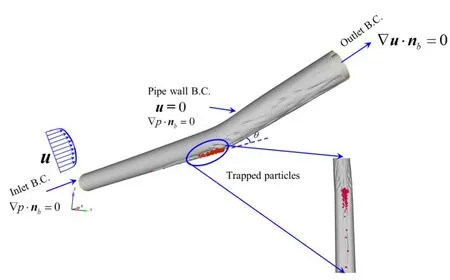
Figure 1:Schematic of the computational domain,initial and boundary conditions adopted in the simulations
As for industry pipelines,the entrance length is much smaller than the development length in pipe flow,the particles are generally in the fully developed flow field.Therefore,this paper focuses on the migration characteristics of particles in the fully developed flow field.According to the above analysis,at the initial moment,it is assumed that the pipeline is in a fully developed state and the particles are still at the bottom of the pipeline.
3 Numerical simulation methods and validations
3.1 Numerical methods
The simulation is achieved via Computational Fluid Dynamics (CFD)coupling with Discrete Element Method (DEM).The CFD code,ANSYS Fluent,was employed to model the continuous phase flow,while the discrete particle motion modeling was accomplished by the DEM code,EDEM.A pressure-based,transient-in-time solver was adopted to solve the oil flow.As described in the Section 2.1,In order to more accurately reflect the variation of velocity over time in the flow field,Large Eddy Simulation method is used to calculate the hydrodynamic parameters of oil in this paper.Bounded second-order implicit scheme is utilized to discretize the transient term of the filtered governing equations.The spatial discretization method consists of gradient,pressure and momentum.The detail discretization methods of spatial derivatives are shown in Tab.1.The pressure-velocity coupling is solved by a PISO (Pressure Implicit Splitting of Operators)technique.
Their coupling of CFD and DEM is numerically achieved as follows.The CFD simulation is iterated to convergence for a time-step.Forces are then calculated on the DEM particles based on the fluid conditions of the mesh cell within which the particle is contained.The DEM solver then takes control of the simulation and performs one (or several)iterations.After the DEM iteration finishes,DEM will give information,such as the positions and velocities of particles,for fluid-particles interaction force in a computational cell.CFD will then use these data to determine the oil flow field at next time step.

Table 1:Discretization methods of spatial derivatives
3.2 Validation of flow field
First,we should check the flow status.To validate the statistics of the flow field without particles added,the boundary layer velocity profile at pipe inlet section is compared to boundary layer theory (see Fig.2).
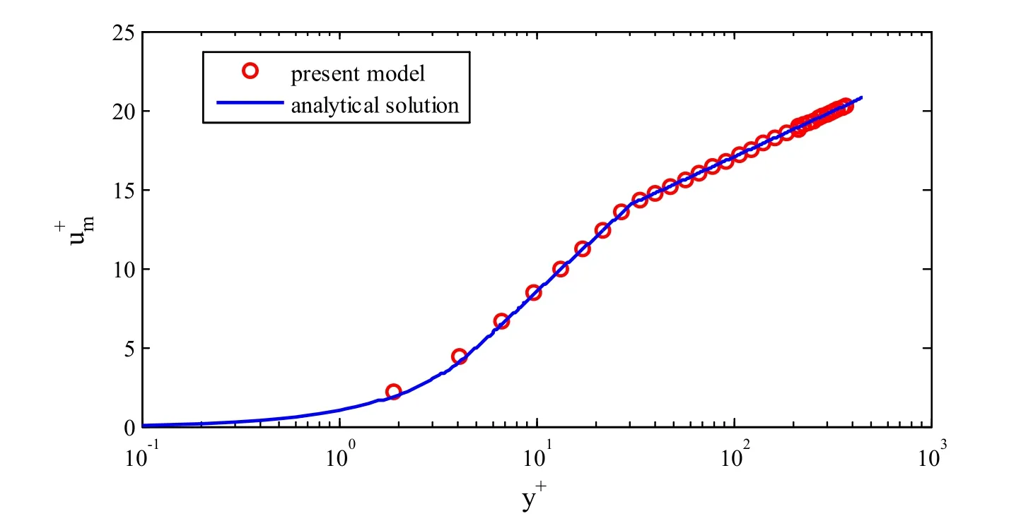
Figure 2:The comparison of mean velocity calculated by LES and boundary layer theory
The bulk velocity in pipeline is 1 m/s,the pipe diameter is 50 mm in Fig.2.From Fig.2,It can be seen that the mean velocity profile obtained from LES approach agrees very well with the typical three-layer-mean-velocity profile of turbulent flow,Thus,the flow field simulated by LES method in present work is reliable.
3.3 Case Study for validating particle migration in fluid
An additional case study was performed to validate the numerical simulation method presented here.The case-study was based on the work on single spherical particle rolling motion in inclined tubes filled with incompressible Newtonian fluids by Jalaal et al.[Jalaal and Ganji (2011)].The schematic of benchmarking case is shown as Fig.3(a).The particle (the diameter is 1 mm)is in a tube inclined with the angle of 15oand filled with the water.For additional details on the case parameters,the interested reader can refer to the original article [Jalaal and Ganji (2011)].In their original work,Jalaal and Ganji established an analytical solution model of settling velocity of single particle in the static flow field of inclined tubes filled with Newtonian fluids.In this section,in order to validate the numerical simulation method proposed in this paper,a comparison of the particle settling velocity versus time from the analytical model by Jalaal et al.[Jalaal and Ganji (2011)] with the results from the current CFD-DEM coupling simulation method has been presented in Fig.3(b).It can be seen that the result calculated by the present model agrees well with analytical solution.

Figure 3:Benchmark comparison of the numerical simulation method developed in this work with analytical model presented by Jalaal et al.[Jalaal and Ganji (2011)].(a)Schematic of validation case.(b)Comparison of particle settling velocity from different method
4 Results and discussion
In this section,we will use the established numerical method to study the hydraulic pigging process of an inclined oil pipeline.
4.1 Case basic parameters of simulation case
The inner diameter of the oil pipeline studied in this paper is 50 mm,and the inclined angles of the pipeline are 9°,12° and 15° respectively,which represent the actual pipeline laid in different undulating terrain environment.The shape of solid particles deposited at the bottom of the pipeline is complex and the particle size is different.There are not only small size iron powders but also large scale sediments generated by corrosion at the bottom of the pipeline.Furthermore,the flow rate in oil pipeline often changes with the demands of the downstream markets,especially in the multiproduct pipelines,the flow rate in different sections of the same pipeline is often different.In view of this,the motion characteristics of trapped particles with different sizes are studied under the conditions of different flow rates in the pipeline with different incline angles.Tab.2 summarizes the main information about the geometry,the flow conditions and the fluid and particle properties of the present study.
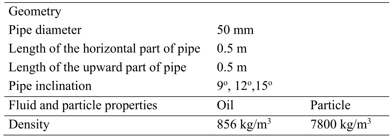
Table 2:Description of the basic parameters simulated
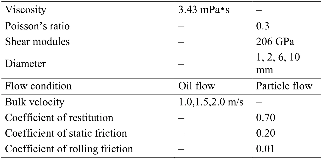
Viscosity 3.43 mPa·s - Poisson’s ratio - 0.3 Shear modules - 206 GPa Diameter - 1,2,6,10 mm Flow condition Oil flow Particle flow Bulk velocity 1.0,1.5,2.0 m/s - Coefficient of restitution - 0.70 Coefficient of static friction - 0.20 Coefficient of rolling friction - 0.01
4.2 Grid-independence solution
The governing equations are solved on the “O-block” mesh with local refinements near pipe wall.In order to eliminate the influence from grid on the numerical results,the grid independence is required to be tested.The flow field is simulated on three sets of meshes,and the axial velocity distributions on the radius of the pipe cross section at 0.25 m are compared.The comparison results are shown in Fig.4.
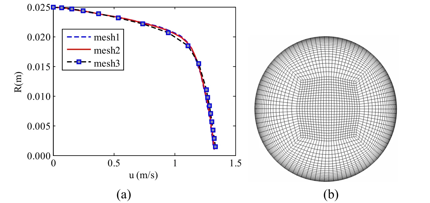
Figure 4:Grid- independence solution.(a)Comparison of the axial velocity at radius calculated on different meshes.(b)“O-block” mesh
The grid numbers of mesh1,mesh2 and mesh3 are 1072246,390848 and 213619,respectively.It can be seen from Fig.4 that axial velocity at radius calculated with mesh1 and mesh2 matches well with each other while the results obtained with mesh3 shows a little difference with the former.Therefore,in this paper,the mesh2 is used in this study.
4.3 Particle migration characteristics
The migration characteristics of solid particles in the pipeline are affected by the pipe inclined angles,pipe flow rates and particle diameters.In this section,the effects of different pipe inclined angles,flow rates and particle diameters on the displacement of the trapped particles are studied.
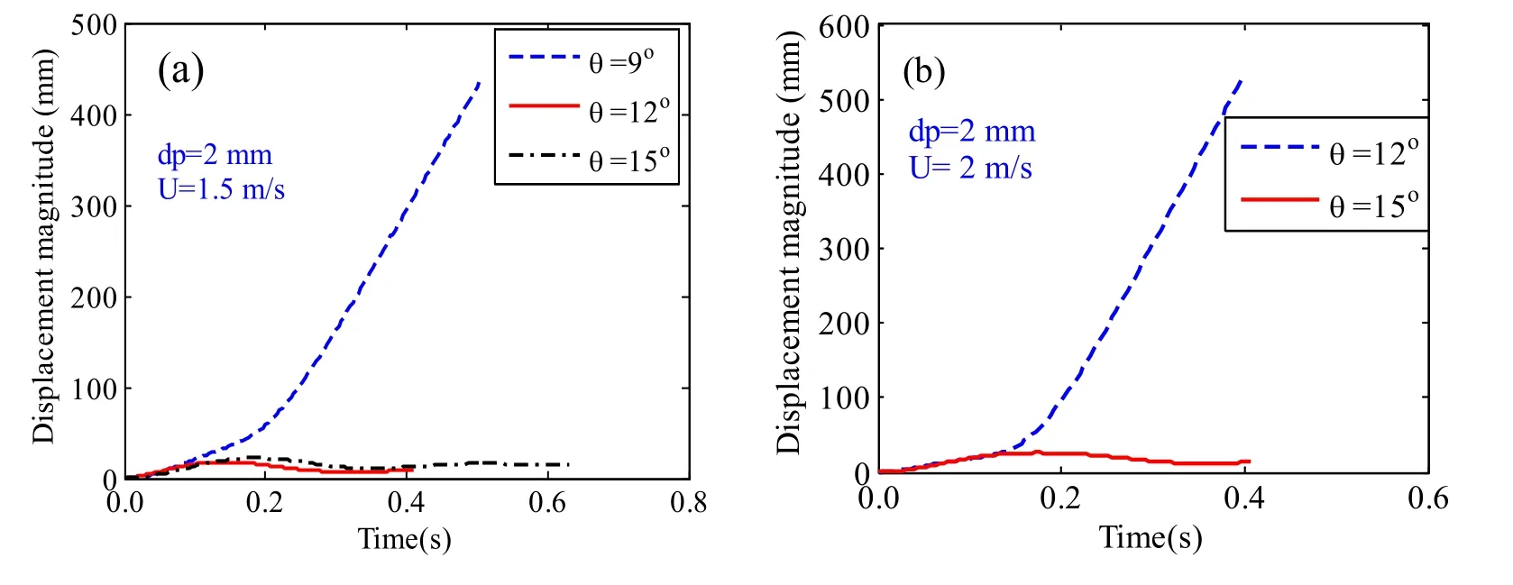
Figure 5:Effect of pipeline inclined angles on the displacement of the trapped particles.dp is the diameter of particle, θ is the inclined angle of pipeline,U is the bulk velocity of oil

Figure 6:The displacement magnitude of the particle which cannot be carried out
Fig.5 shows the particle displacement versus time under the condition that the particle diameter and the oil bulk velocity remain constant.The oil bulk velocities in Figs.5(a)and 5(b)are 1.5 m/s and 2.0 m/s,respectively,and the particle diameter is 2 mm.It can be obtained from Fig.5 that only the particles in the pipelines whose inclined angles are 9oand 12ocan be flushed out by oil stream.The reason is that the smaller the inclined angle of the pipe,the less the influence of gravity,and the smaller the resistance in the movement of the particles.Thus,the particles in small inclined angle of pipelines are easily carried out by oil flow.According to the slope of particle displacement curve with time,it can be seen that the particle velocity increases gradually during the hydraulic pigging process.When the particle reaches the inclined section of the pipeline,the particle is flushed out of the pipe approximately at a uniform velocity.It can also be seen from Fig.6 that the displacements of particles which cannot be flushed out of the pipeline are similar to that of damped vibration.
The reason behind the phenomenon revealed in Fig.6 is that the trapped particle gradually rises to the inclined section of the pipe due to the forces from oil stream,In the process of particle rising,the component of gravity in the direction of motion increases gradually,and the velocity of the particles decreases gradually.When the particle reaches a certain position,the kinetic energy of the particle is converted to potential energy and friction loss energy,and then,under the effect of gravity,the particle resettles and moves to the bottom of the pipe.During the process of particle settling,the particle is carried by the forward oil flow,and the velocity decreases gradually.When the particle velocity decreases to zero,it is flushed by oil flow again.However,due to the energy loss caused by the interaction between particle and pipe wall and particle and fluid,the height of particles carried by oil flow gradually decrease,which is revealed by the decay of particle displacement curve with time in Fig.6.
Figs.7(a)and 7(b)show the displacements of the particles whose diameter is 6 mm in the inclined pipelines under different oil bulk velocities.It can be seen from Fig.7 that increasing the oil flow rate can speed up the movement of particles.Solid particles are mainly affected by the drag force in the flow field,and the drag force is positively correlated with the relative velocity of the particle and the fluid.Thus,the greater the bulk velocity of oil in the pipeline,the greater the drag force act on the particles,so increasing the velocity of flow can improve the efficiency of hydraulic pigging.However,with the increase of bulk velocity of oil stream,the pressure gradient along the pipeline will increase.According to the model of pressure gradient force (Eq.(6)),it can be obtained that the larger the pressure gradient,the greater the pressure gradient force acting on the particles,which makes it easier for particles to be carried out of the pipeline.Unfortunately,it should be noted that the large flow rate in the pipeline will increase the friction along the pipelines,which means that the operation cost of the pipeline will increase.Besides,there is also a limit to the maximum flow rate in the industry oil pipeline,especially in multiproduct pipelines.Therefore,whether or not the trapped particles can be flushed out of the pipeline by increasing the flow rate should be judged according to the actual operating conditions of the pipeline.From the above analysis,it can be obtained that it is not the optimal method to increase the hydraulic pigging efficiency by increasing the oil flow rate in pipelines.
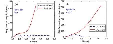
Figure 7:Effect of oil bulk velocity on the displacement of the trapped particle.dp,θ and U has the same meaning with them in Fig.5
Fig.8 shows that the displacements of different particles versus time under the conditions of keeping the oil flow rate and pipeline inclined angle constant (Figs.8(a),8(b)and 8(c)represents the pipe with different inclined angles and flow rates in the pipeline).It can be seen from Figs.8(a),8(b)and 8(c)that the particles carried out from the pipelines by the oil flow are the medium scale particles,while the small and large particles cannot be removed.That is to say the oil stream,carrier phase,can only flush out the solid particles in a certain diameter range under the given operation conditions,and the particles whose diameter beyond that diameter range will cannot be removed out from the pipeline.

Figure 8:Effect of particle diameter on the displacement of the trapped particle.dp,θ and U has the same meaning with them in Fig.5
4.4 Enhanced hydraulic pigging method based on multi-physical field cooperation
In Section 4.3,we find that the small diameter particles deposited at the bottom of the inclined pipelines are very difficult to be flushed out by the flowing oil.It is a very uneconomical way to flush small diameter particles out from the pipelines only by increasing the flow rate.In view of this,an Enhanced Hydraulic Pigging Method Based on Multi-physical Field Collaboration (EHPM-MPFC)is proposed in this section.
Guiding the solid particles to the target position by external physical filed has been actively investigated in other science and industry areas.In the medical field and nanoscale problems,guiding particles to target cells using external fields was researched by Peasley [Peasley (1996)].Following their idea of guiding particles by magnetic field in the micro and nano scale problems,we use the external magnetic field to assist the displacement of solid particles.It is should note that the pipe wall corrosion generates sediments,such as iron oxide (Fe2O3or Fe3O4),is the main source of solid impurities in the pipeline,and Fe3O4is a kind of magnetic solid materials.Thus,we can use the external magnetic field to guide the particles to move out of the pipelines.
The magnetic field is referred to the work of Mukherjee et al.[Mukherjee,Zaky and Zohdi (2015)].The mathematical model of the magnetic field generated by a magnetic dipole can be written as follows:

where,Bis the magnetic induction intensity,T.B0is the scalar valued magnitude of the magnetic field,T.αis a scalar valued,dimensionless.r′is the position vector measured from the magnetic dipole.
The magnetic induction intensity distribution near an inclined pipeline is shown in Fig.9.It can be seen from Fig.9 that the distribution of magnetic induction intensity in spatial around the magnetic pole is similar to that of the electric field around the point charge.The closer to the magnetic pole,the greater the magnetic induction intensity is.

Figure 9:The magnetic field strength spatial distribution of a fixed magnetic dipole.where, B0=1.5 Tα=2,position of the fixed magnetic dipole is (0.98,0,-0.1025)
In order to validate the pigging efficiency of EHPM-MPFC proposed in this work,we compared the variation of particle displacements calculated by the EHPM-MPFC with that obtained from HPM.In Fig.10,the inclined angle of the pipeline is 15°,the oil bulk velocity in the pipeline is 2 m/s,and the particle diameter is 2 mm.From Fig.10,it can be seen that under the assistance of external magnetic field,the particle migration velocity is very fast,and the pigging efficiency is greatly increased,which proves the effectiveness of EHPM-MPFC.From the above analysis,it is obtained that the particle can be carried out from the pipelines very efficiently by using EHPM-MPFC,especially for the small-scale particles which cannot be flushed out by using the oil flow alone.

Figure 10:The displacement of the trapped particles which cannot be carried out obtained from HPM and EHPM-MPFC
5 Conclusion
This article presented a numerical study of trapped particles displacement from the low section of an inclined oil pipeline.A numerical model governing hydraulic pigging process is established in Euler-Lagrangian framework.The simulation is achieved via CFD coupling with DEM.In order to resolve the detail information of the flow field in pipeline,LES approach is utilized to simulate the turbulence pipe flow.Furthermore,an enhanced hydraulic pigging method based on multi-physical field cooperation (EHPMMPFC)is proposed and proved to improve the efficiency of HPM.The particles migration characteristics are analyzed in detail.The numerical results show:
(1)The displacements of particles which cannot be flushed out of the pipe are similar to that of damped vibration.
(2)The particles most easily carried out of the pipeline by the oil flow are the medium scale particles,while the small-scale or large-scale particles are difficult to be removed.This means that the oil stream,carrier phase,can only flush out the solid particles in a certain diameter range under the given operation conditions,and the particles whose diameter beyond that diameter range will cannot be removed out from the pipeline by HPM.
(3)The solid particles can be carried out from the pipelines very efficiently by using EHPM-MPFC,especially for the small-scale particles which cannot be flushed out by using the HPM alone.
These findings in the present work provide the requisite basis necessary for the appropriate design of hydraulic pigging scheme in industry multiproduct pipelines.
Acknowledgement:This work is part of the program of “The research on the optimization and supply-side reliability of oil product logistics system (No.51874325)”,which is funded by the National Natural Science Foundation of China.
杂志排行
Computer Modeling In Engineering&Sciences的其它文章
- Forced Vibration of the Non-Homogeneously Pre-Stressed System Consisting of the Hollow Cylinder and Surrounding Medium
- Dynamic Analyses of a Simply Supported Double-Beam System Subject to a Moving Mass with Fourier Transform Technique
- Analytical and Numerical Solutions of Riesz Space Fractional Advection-Dispersion Equations with Delay
- 3-D Thermo-Stress Field in Laminated Cylindrical Shells
- Seismic Fragility Analysis of Long-Span Bridge System with Durability Degradation
- Partitioned Method of Insect Flapping Flight for Maneuvering Analysis
