Partitioned Method of Insect Flapping Flight for Maneuvering Analysis
2019-11-26MinatoOnishiandDaisukeIshihara
Minato Onishi and Daisuke Ishihara,
Abstract: This study proposed a partitioned method to analyze maneuvering of insects during flapping flight.This method decomposed the insect flapping flight into wing and body subsystems and then coupled them via boundary conditions imposed on the wing’s base using one-way coupling.In the wing subsystem,the strong coupling of the flexible wings and surrounding fluid was accurately analyzed using the finite element method to obtain the thrust forces acting on the insect’s body.The resulting thrust forces were passed from the wing subsystem to the body subsystem,and then rigid body motion was analyzed in the body subsystem.The rolling,yawing,and pitching motions were simulated using the proposed method as follows:In the rolling simulation,the difference of the stroke angle between the right and left wings caused a roll torque.In the yawing simulation,the initial feathering angle in the right wing only caused a yaw torque.In the pitching simulation,the difference between the front- and back-stroke angles in both the right and left wings caused a pitch torque.All three torques generated maneuvering motion comparable with that obtained in actual observations of insect flight.These results demonstrate that the proposed method can adequately simulate the fundamental maneuvers of insect flapping flight.In the present simulations,the maneuvering mechanisms were investigated at the governing equation level,which might be difficult using other approaches.Therefore,the proposed method will contribute to revealing the underlying insect flight mechanisms.
Keywords: Insect flapping flight,maneuverability,fluid-structure interaction,partitioned method,projection method,strongly coupled method,one-way coupling,finite element method.
List of abbreviations
aradius of the insect body
CaCauchy number
Cθcompliance of the torsion of the wing
cmwing mean chord length
fφflapping frequency
Jimoment of inertia of the body in thei-th direction
Lbody length
Lwwing span length
Mmass ratio
mbmass of the insect body
ReReynolds number
rAaspect ratio of the wing
r2non-dimensional radius of the second moment of the wing area
Spprojection area of the wing chord normal to the translational direction
SWarea of the wing surface
Titorque due to the force acting the body in thei-th direction
Tφflapping period
Vmmean flapping velocity
Vmaxmaximum velocity of the wing due to the body rotation
αnon-dimensional parameter
θfeathering angle
θ0initial feathering angle
θ0Rright wing’s initial feathering angle
θ0Lleft wing’s initial feathering angle
μffluid viscosity
ζangle of inclination in the body axis
ρffluid mass density
Φstroke angle
ΦLleft wing’s stroke angle
ΦRright wing’s stroke angle
ΦFfront stroke angle
ΦBback stroke angle
φstroke angular displacement
ψirotation angle of the body in thei-th direction
1 Introduction
Insects have developed flapping flight through their evolutionary history [Brodsky (1994)].This flight is superior to other forms of locomotion and has resulted in their habitat extending over the entire planet.Therefore,the flapping flight of insects has attracted much attention of researchers.
The characteristic motions of an insect’s flapping wings were observed using high-speed video camera recordings [Weis-Fogh (1973)],and the kinematics have been investigated extensively in many studies [Ellington (1984b);Walker,Thomas and Taylor (2010);Chen,Skote,Zhao et al.(2013);Chen and Skote (2015)].Dynamically scaled experiments based on the kinematics of the insect’s flapping wings revealed that (1)the fluid flow forms a vortex at the leading edge of the wings,(2)this vortex is stable during the flapping translation,and (3)it creates enough lift force for the insect to fly [Dickinson,Lehmann and Sane (1990);Ellington,Van den Berg,Willmott et al.(1996)].The kinematics of the insect’s flapping wings can be caused by the interaction of the wing and surrounding fluid [Ishihara and Horie (2006);Ishihara,Horie and Denda (2009);Ishihara,Yamashita,Horie et al.(2009)].
Most recently,flapping-wing nanoscale air vehicles mimicking insects have been developed [Wood (2008);Ma,Chirarattananon,Fuller et al.(2013);Bontemps,Vanneste,Paquet et al.(2013)].These devices are expected to be capable of the sophisticated maneuvers seen in insect flapping flight.However,the underlying mechanism of these maneuvers is still unclear.Here,we focus on how maneuvering parameters such as the stroke and initial feathering angles give maneuvering motions.This relationship is complicated and nonlinear,and it is not revealed yet.This is because there is no approach to analyze this relationship directly.Therefore,the objective of this study is to develop an analysis method to investigate and demonstrate this relationship at the governing equation level,which might be difficult using other approaches.
Several approaches are available for revealing the maneuvering mechanism of the insect flapping flight.High-speed video camera recordings give the kinematics of the insect’s wing and body during maneuvering.Computational fluid dynamics can analyze the associated fluid mechanics [Liu,Ellington,Kawachi et al.(1998);Hamdani and Sun (2000);Ramamurti and Sandberg (2002);Aono,Liang and Liu (2007)].Furthermore,an approach taking into account the fluid-structure interaction is necessary,because the insect’s wings and the surrounding fluid are coupled to cause the wing’s characteristic motions that result in the enough lift force for the insect to hover [Ishihara,Yamashita,Horie et al.(2009);Ishihara,Horie and Niho (2014)].The deformation of the insect’s wings can change vortices around them to enhance the aerodynamic performance [Nakata and Lie (2012);Nguyen,Sundar,Yeo et al.(2016)],and it can reduce the vibration of the insect’s body to contribute stabilization of insect flapping flight [Yao,Yeo and Nguyen (2019)].
There are essentially two computational methods for the fluid-structure interaction,that is,the strongly and weakly coupled methods [Zhang and Hisada (2004)].In the strongly coupled method,the formulation enforces the coupled conditions on the fluid-structure interface.In contrast,in the weakly coupled method,the formulation does not enforce the coupled conditions on the fluid-structure interface.Therefore,the strongly coupled method is necessary to solve strongly coupled problems.A weakly coupled method was applied to the interaction of the insect’s wings and the fluid surrounding the insect [Nakata and Liu (2012);Eberle,Reinhall and Daniel (2014)].However,the insect’s wings and the fluid surrounding the wing are strongly coupled because of the high flexibility of the wings [Yamada and Yoshimura (2008);Ishihara,Horie and Denda (2009)].A monolithic formulation of the insect’s wing and body in the fluid-structure interaction analysis using the strongly coupled method is very expensive computationally [Nakata and Liu (2012);Nakata,Noda and Liu (2018);Yao,Yeo and Nguyen (2019)] and leads to numerical difficulties.Therefore,a different approach is required.
Hovering is the most fundamental flight mode [Ellington (1984a)],and turning behaviors initiated from quasi-static flight are justified for maneuvering [Bergou,Ristroph,Guckenheimer et al.(2010);Beatus and Cohen (2015);Whitehead,Beatus,Canale et al.(2015)].Therefore,each body rotation for rolling [Beatus and Cohen (2015)],yawing [Bergou,Ristroph,Guckenheimer et al.(2010)],or pitching [Whitehead,Beatus,Canale et al.(2015)] from the static state is taken as the basis of maneuvers during insect flapping flight.
It seems that the insect uses the stroke angle and initial feathering angle for maneuvering [Bergou,Ristroph,Guckenheimer et al.(2010);Beatus and Cohen (2015);Whitehead,Beatus,Canale et al.(2015)].These parameters must change at the wing’s base because the insect’s wing lacks internal muscles [Wootton,Herbert,Young et al.(2003)].This understanding suggests that these changes can be described as the boundary conditions imposed on the wing’s base.Furthermore,it follows from this description that the insect flapping flight can be partitioned into the wing and body subsystems,and it can be considered as their coupling via boundary conditions imposed on their interface,that is,at the wing’s base.
In this study,a partitioned method for maneuvering analysis of insect flapping flight is proposed.In the proposed method,the insect flapping flight is partitioned into the wing and body subsystems,and they are coupled via the boundary conditions imposed on their interface at the wing’s base using partitioned algorithms.The boundary conditions describe not only the coupled conditions but also the transmission functions of the wing’s base,including the maneuvering parameters.This formulation allows us to solve the strong coupling of the wing and the fluid surrounding the wing separately to avoid the numerical difficulties of applying the strongly coupled method to the whole system.
This study demonstrates the fundamental validity of the proposed method for the maneuvering analysis of insect flapping flight.Here,one-way coupling was used because it is one of the simplest partitioned algorithms.In the wing subsystem,the thrust force is calculated by a strongly coupled analysis of the wing and surrounding fluid.This force is passed to the body subsystem,and the motion of the body is calculated by rigid body analysis.The maneuvers simulated using the proposed method were compared with those in previous studies.As far as we know,no other study has evaluated the maneuvers of the body motion with simulations that account for the fluid-structure interaction of the wings.This might be because of the numerical difficulties stemming from a monolithic formulation of the insect’s wings and body in the fluid-structure interaction.
2 Partitioned method of insect flapping flight
2.1 Partitioned modeling
The flexible wings and surrounding fluid are strongly coupled to produce the characteristic motions of the wings and create enough lift for the insect to hover [Ishihara,Yamashita,Horie et al.(2009);Ishihara,Horie and Niho (2014)].This result indicates that the fluid-structure interaction is essential in the insect flapping flight mechanism.Thus,a strongly coupled method is required to solve this problem [Yamada and Yoshimura (2008);Ishihara,Horie and Denda (2009)].However,the monolithic formulation of the wings and the body in the fluid-structure interaction leads to numerical difficulties [Nakata and Liu (2012)].
To resolve this issue and reveal the underlying mechanism of flapping flight maneuvers,a partitioned method for insect flapping flight is proposed based on the model shown in Figure 1.As shown in this figure,the insect flapping flight is decomposed into the subsystems of the wing and body,and these subsystems are coupled via boundary conditions at the wing’s base.These boundary conditions include the coupled conditions that consist of compatible and equilibrium equations.In addition to these conditions,these boundary conditions include the transmission functions of the wing’s base,including the insect’s control of the maneuvering parameters.
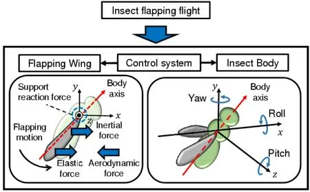
Figure 1:Proposed partitioned model of insect flapping flight
The proposed model allows us to solve the strong coupling of the wings and their surrounding fluid separately,which avoids the numerical difficulties of applying the strongly coupled method to the whole system.The underlying physical interpretations on the proposed modeling are described below.
Parameters for maneuvering,such as the stroke angle and initial feathering angle [Bergou,Ristroph,Guckenheimer et al.(2010);Beatus and Cohen (2015);Whitehead,Beatus,Canale et al.(2015)],are thought to be controlled actively by the insect at the wing’s base because insect wings lack internal muscles [Wootton,Herbert,Young et al.(2003)].This means that their control can be described by boundary conditions imposed on the interface between the wing and the body,that is,at the base of the wing.This description can also be justified as a reduced-order model by taking into account the complexities of the wing’s base [Beatus and Cohen (2015)],which is among the most complicated joints in the animal kingdom [Pringles (1957);Dickinson and Tu (1997)].
Furthermore,the mechanical characteristics of the wing subsystem and body subsystem are quite different from each other.A strong interaction between the fluid and the structure occurs in the wing subsystem because of the wing’s high flexibility.In contrast,the body subsystem presents a different type of fluid-structure interaction problem because of its small elastic deformation.The characteristic frequency of the wing subsystem is the flapping frequency,which is several hundred hertz,and it essentially represents an unsteady problem.In contrast,the body subsystem presents a far lower characteristic frequency during flight:hovering is the most fundamental mode [Ellington (1984a)],and the turning behaviors from quasi-static flight can be considered as maneuvers [Bergou,Ristroph,Guckenheimer et al.(2010);Beatus and Cohen (2015);Whitehead,Beatus,Canale et al.(2015)].
To discuss the fundamental validity of the proposed method,one-way coupling is used in the partitioned algorithm;that is,the thrust force from the wing subsystem is passed to the body subsystem at the wing’s base.This method can be justified by the physical interpretation of the maneuver.Each body rotation to produce rolling [Beatus and Cohen (2015)],yawing [Bergou,Ristroph,Guckenheimer et al.(2010)],or pitching [Whitehead,Beatus,Canale et al.(2015)] from the static state is the basis of the maneuvers during insect flapping flight.This method can also be justified by the actual observation of the maneuver.The yaw angle Δψ=120° is produced by Δt=80msec from actual data [Bergou,Ristroph,Guckenheimer et al.(2010)].Therefore,the wing speed due to the body rotation along the flapping direction is approximately evaluated asr2LwΔψ/Δt=0.034 m/sec,wherer2andLware the nondimensional radius of the second moment of the wing area and the wing span length,respectively,and these values are set as 0.545 and 2.39×10⁻⁶m,respectively,from actual data [Cheng and Deng (2011);Hedrick,Cheng and Deng (2009)].In contrast,the mean speed of flapping wings is given by 2r2ΦLwfφ=1.4 m/sec,whereΦandfφare the stroke angle and the flapping frequency,and these values are set as 140° and 218 Hz,respectively,from actual data [Hedrick,Cheng and Deng (2009)].The former is ignorable because it is only 2% of the latter.In the following sections,the modeling of each subsystem is described.
2.2 Wing subsystem
2.2.1 Governing equation
Insect wings consist of thin membranes to capture the aerodynamic force and a network of veins to support them.They are quite flexible,especially regarding torsion [Ennos (1987,1988a)].According to actual measurements [Combes and Daniel (2003)],the rigidity along a wing’s chord-wise direction is approximately two orders smaller than that of a wing’s span-wise direction.Insect wings lack internal muscles,and any changes in shape that they undergo in flight must be driven by external forces [Wootton,Herbert,Young et al.(2003)].In general,therefore,an insect wing is an elastic body,and its behavior can be described by the following equation:

where d/dtis the Lagrangian time derivative,the superscript s stands for a structural quantity,ρis the mass density,viis theith component of the velocity vector,σijis theijth component of the Cauchy stress tensor,andgiis theith component of the body force.
The wing’s base,which is the interface between the wing and body,works as a transmission [Ennos (1987)];i.e.,it redirects power from the main flight muscles to the wing,and,inversely,the aerodynamic force acting on the wing to the body.The wing’s base consists of multiple steering muscles,tendons,and both flexible and rigid parts,and it is among the most complicated joints in the animal kingdom [Pringle (1957);Dickinson and Tu (1997)].Therefore,a reduced-order approach is useful to summarize this seemingly intractable behavior,because it provides a framework for characterizing complexity [Beatus and Cohen (2013)].In this study,the transmission function of the wing’s base is described using fundamental and natural boundary conditions imposed on the wing’s base.
The Reynolds number of the fluid surrounding the insect’s wings is typically less than 1,000.Therefore,its behavior can be described by the incompressible Navier-Stokes equations using the arbitrary Lagrangian-Eulerian method [Hughes,Liu and Zimmerman (1981)] as follows:

where ∂/∂tis the arbitrary Lagrangian-Eulerian time derivative,the superscript f stands for a fluidic quantity,andvmiis theith component of the velocity vector of the arbitrary Lagrangian-Eulerian coordinate.
The following coupled conditions are satisfied on the interface between the insect’s wing and the surrounding fluid:

wherenfiandnsiare theith components of the outward unit normal vectors on the fluidstructure interface corresponding to the fluid and the structure,respectively.The coupled conditions should be satisfied implicitly,because the insect wing and surrounding fluid are strongly coupled.
2.2.2 Lumped torsional flexibility model
Many observations have reported the flexibility of insect wings during flapping flights with various modes of deformation.The most significant among them is the high torsional flexibility,which is concentrated on the narrow wing basal and short root regions.This flexibility is important in insect flapping flight because the feathering motion is essential for lift generation.Therefore,the lumped torsional flexibility model shown in Fig.2 has been successfully used in numerical fluid-structure interaction analysis of insect flapping wings [Ishihara and Horie (2006);Ishihara,Horie and Denda (2009);Zhang,Liu and Lu (2010);Masoud and Alexeev (2010);Spagnolie,Moret,Shelley et al.(2010);Dai,Luo and Doyle (2012);Kang and Shyy (2013);Xiao,Hu and Liu (2014);Ishihara,Horie and Niho (2014);Kolomenskiy,Maeda,Engels et al.(2016);Ishihara and Horie (2016);Wang,Goosen and Keulen (2017);Ishihara (2018)].
As shown in Fig.2,the torsional flexibility is described by a torsional spring,and the wing’s chord is expressed by a rigid plate connected to a spring at one end.The forced displacement describing the flapping motion is imposed on the other end of the spring.The plate translates,and a fluid dynamic force acts on the plate to cause torsional oscillation.
Three-dimensional features are quite essential in the insect flapping flight maneuver.The thrust forces from the insect’s wings cause yawing,rowing,and pitching for maneuvering.The flapping translation of the insect’s wing forms a three-dimensional leading edge vortex stably to create enough aerodynamic forces [Ellington,Van den Berg,Willmott et al.(1996);Dickinson,Lehmann and Sane (1990)],and,inversely,these forces cause the characteristic feathering motion [Ishihara,Yamashita,Horie et al.(2009);Ishihara,Horie and Niho (2014)].
In this study,therefore,a three-dimensional implementation of the lumped torsional flexibility model was used,as shown in Fig.3,where the plate spring is the implementation of the lumped torsional flexibility,and it connects the stiff leading edge beam and the stiff wing plate.The motivation of this model wing is the accuracy of the numerical analysis for the flapping wing in a fluid.This model wing can be implemented accurately using the finite element mesh,as shown in Fig.4,where rectangular shell elements are used.Because of the small error of finite element modeling in contrast to the case of a torsional spring,the finite element analysis for this model wing has been sufficiently validated using a corresponding dynamically scaled experiment [Ishihara,Horie and Niho (2014);Ishihara and Horie (2016)].Actually,the plate spring can be set such that it works as a lumped torsional flexibility;that is,it simplifies the complicated elastic behavior of insect wings to a fundamental pitching mode.The result demonstrating this consistency is described in our previous work [Ishihara (2018)].
The mean aerodynamic force acting on the wing depends on the nondimensional radiusr2of the second moment of the wing area [Weis-Fogh (1973);Ellington (1988a)].In many insects,r2is very close to that of a rectangular wing at 1/30.5[Ellington (1988a);Ennos (1989)].Therefore,for the sake of simplicity,a rectangular model wing is used as discussed in our previous study [Ishihara,Horie and Niho (2014)],where the difference of results between rectangular and realistic wings is not so significant.
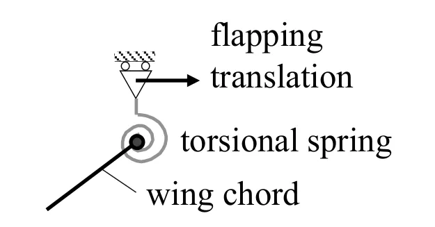
Figure 2:Lumped torsional flexibility model

Figure 3:Three-dimensional implementation of the lumped torsional flexibility model
2.2.3 Modeling of wing motion
The flapping translates the wing from back to front (down-stroke)and front to back (upstroke)as shown in Fig.5.As described in Section 2.2.2,this motion can be described as a fundamental boundary condition imposed on the base of the model wing.The flapping motion can be described using the stroke angular displacementφ,which is positive for the counter-clockwise direction about the flapping axis.The amplitude ofφis denoted by the stroke angleΦ.The time history of dφ/dtcan be given as shown in Fig.6,which is based on actual observation [Ellington (1984b)].In this figure,the flapping frequency and period are described usingfφandTφ,respectively.The time history ofφshown in Fig.7 is given from the time integration of Fig.6.
These time histories are applied to the base of the stiff leading edge.The model wing flaps in the surrounding fluid and is strongly coupled with the fluid to cause a feathering motion passively [Ishihara,Yamashita,Horie et al.(2009)].The feathering motion can be described using the feathering angular displacementθ,which is positive in the counterclockwise direction about the torsional axis.

Figure 4:Finite element model wing using rectangular shell elements
The insect uses the initial feathering angle and the change in the stroke angle for maneuvering [Bergou,Ristroph,Guckenheimer et al.(2010);Beatus and Cohen (2015);Whitehead,Beatus,Canale et al.(2015)].As shown in Fig.5,the proposed modeling can describe this process using the initial feathering angleθ0andΦ.
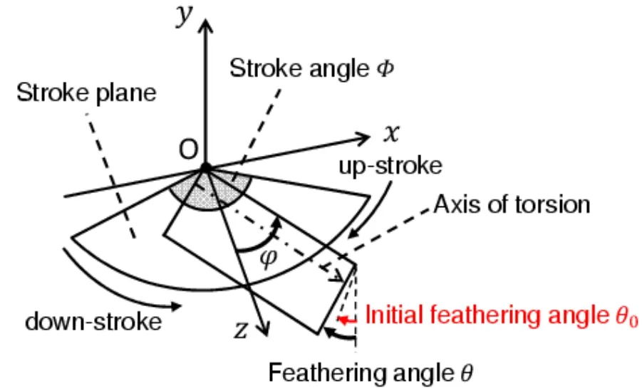
Figure 5:Schematic of the flapping motion

Figure 6:Time history of the stroke angular velocity

Figure 7:Time history of the stroke angular displacement
2.3 Modeling of body subsystem
The proposed partitioned modeling allows us to describe the body motion in a way different from that of the wing.Taking into account the far smaller elastic deformation of the body,it can be modeled as a rigid body.The rotation about thex-axis,or rolling;the rotation about they-axis,or yawing;and the rotation about thez-axis,or pitching from the static state,are considered here as the insect flight maneuvering.Then,the behavior of the body during maneuvering can be described using the following equation:

where matrix J is the moment of the inertia of the body;vector ψ is equal to [ψx,ψy,ψz]T;ψx,ψy,andψzrepresent the roll,yaw,and pitch angles,respectively;the superscript T is the transpose;the vector M is equal to [Mx,My,Mz];andTx,Ty,andTzare the moments about thex-axis,y-axis,andz-axis,respectively,acting on the body.
In the case of rotation of the rigid body from the static state,the interaction from the surrounding fluid can be evaluated as additional mass and viscosity.In the case of air,however,these effects are very small [Nomura and Hughes (1992)].Therefore,they are ignored in this study.

Figure 8:Schematic of the body subsystem
3 Numerical methods
3.1 Fluid-structure interaction analysis of wing subsystem
3.1.1 Projection method for the monolithic fluid-structure interaction system
Eqs.(1)-(3)were discretized using the finite element method and combined using Eqs.(4)and (5)to obtain a monolithic equation system for the fluid-structure interaction [Zhang and Hisada (2001);Ishihara and Yoshimura (2005);Ishihara and Horie (2014)] as follows:

where M,C,and G are the mass,diffusive,and divergence operator matrices,respectively,and N,q,g,a,v,u,and p are the convective term,elastic internal force,external force,acceleration,velocity,displacement,and pressure vectors,respectively.The subscript L represents the lumping of the matrix,and the superscript T indicates the transpose of the matrix.
The monolithic method solves Eqs.(7)and (8)simultaneously [Rugonyi and Bathe (2001)].Because this formulation enforces coupled conditions (4)and (5),the method is strongly coupled,and it avoids spurious numerical power on the interface,which yields numerical instability [Fernandez,Gerbeau and Grandmont (2007)].However,this formulation leads to an ill-conditioned system of equations.
In this study,therefore,a projection method using algebraic splitting was used to avoid this difficulty [Ishihara and Yoshimura (2005);Ishihara and Horie (2014)].The monolithic equation system consisting of (7)and (8)was linearized and split into equilibrium equations and a pressure Poisson equation as follows:

where a*is the intermediate acceleration;v*is the intermediate velocity;M*is the generalized mass matrix,which consists of the lumped mass and tangential stiffness matrices;Δ andtare the variable increment and time,respectively;and Δg is the residual vector of Eq.(7).Note that the relationships among the state variables based on Newmark’s method are used in these equations.In the nonlinear iteration of each time step,first,the equilibrium Eq.(9)is solved to derive the intermediate velocity field v*,then the pressure Poisson Eq.(10)is solved to derive the current pressure field p such that the current velocity field satisfies the incompressibility constraint (8),and,finally,the equilibrium Eq.(11)is solved to derive the current velocity field v.
3.1.2 Dynamic similarity law for fluid-structure interaction systems
The nondimensional parameterα[Wang,Birch and Dickinson (2004);Katz and Plotkin (2001)],the Reynolds numberRe[Katz and Plotkin (2001)],the Cauchy numberCa[Chakrabarti (2002)],and the mass ratioM[Blevins (1990);Sedov (1993);Dowell (1999)] can be obtained from the dimensional analysis for the governing Eqs.(1)-(5)as follows:

wherefφis the flapping frequency,cmis the mean chord length,Vm(=2r2ΦLwfφ)is the mean flapping velocity,r2is the second moment of the wing area,Φis the stroke angle,Lwis the wing span length,rA(=2Lw/cm)is the aspect ratio of the wing,ρfis the fluid mass density,μfis the fluid viscosity,Cθis the compliance of the torsion of the wing,andmwis the mass of the wing.These four nondimensional parameters can make two different fluid-structure interaction systems dynamically similar to each other.This dynamic similarity law is used to incorporate data from the actual insects into the model wing [Ishihara,Yamashita,Horie et al.(2009);Ishihara,Horie and Niho (2014);Ishihara and Horie (2016);Ishihara (2018)].
3.2 Dynamic analysis of body subsystem
Morphological data for actual insects shows broad variation,even in the same species [Ellington (1984a)].In this study,therefore,instead of measuring the exact shape of each individual,a shape simplification approach was used.The insect’s body was approximated using a rigid circular cylinder [Ellington (1984a)],as shown in Figure 9.The height and the mass of the cylinder were set as the mean body lengthLand weightmbfrom actual insect data,respectively.These two dimensions can be obtained from several studies [Ellington (1984a);Ennos (1989)].In contrast,the radius of the body is not available directly.Therefore,it was set toa=L/6,L/4,andL/2 under the assumption that this range can cover the minimum and maximum radii.Furthermore,the nondimensional radius of gyrationl2=Jb/(mbL2)(Jb:the moment of inertia of the body,which applies to pitching movements of insects)is given as 0.315 for flies in the previous study [Ellington (1984a)].In this study,Jbcorresponds toJz,which is given below.Therefore,Jzis set such that it is equal toJbin this study.From this equality,a kinematically equivalent radiusais given as 0.252L,which is very close toL/4.The mass density distribution was assumed to be uniform [Ellington (1984a)].The center of gravity was placed at the origin of a Cartesian coordinate system.They-axis corresponded to the longitudinal axis of the body,that is,the angle of inclination in the body axisξ=0°.Then,the governing equation of the rigid body (6)was reduced to

whereJi,ψi,andTiare the moment of the inertia of the body,the rotation angle of the body,and the torque due to the external force acting on the body inith direction of the Cartesian coordinate system,orx-,y-,orz-direction.Jiis given as

Eq.(16)is solved using Newmark’s β method.

Figure 9:Approximation of the body using a rigid cylinder
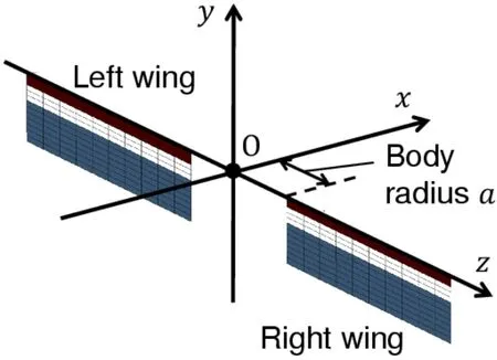
Figure 10:Pair of model wings for calculating the torques acting on the rigid cylinder
As described in Section 2.1,the thrust force generated by the wing subsystem is passed to the body subsystem.This transfer is achieved as follows:
Let us consider a pair of model wings as shown in Fig.10.The aerodynamic forces acting on each wing are calculated using the strongly coupled method in Section 3.1.These aerodynamic forces are in equilibrium with the reaction forces from the body at the wing base,which supports the model wings.Therefore,the aerodynamic forces acting on the model wings in Fig.10 are considered as the thrust forces given to the body,and they are used to calculateTiin Eq.(16).
3.3 Coupling of wing and body subsystems
The one-way coupling between the wing and body subsystems used in this study can be described as

where T is the moment acting on the insect’s body,r is the position vector of each point on the wing surface from the gravity center of the insect’s body,f is each fluid surface force acting on the point,andSWis the area of the wing surface.f is the function of the maneuvering parameters,and it can be expressed as

whereΦ,θ0,and ΔΦare the stroke angle,initial feathering angle,and difference of the front and back stroke angles.Upon the finite element discretization,Eq.(19)can be rewritten as

where rnis the position vector of nodenfrom the gravity center of the insect’s body,fnis the equivalent nodal force corresponding to the fluid surface force,and NWis all nodes composing the finite element mesh of model wings.
4 Analysis setups
As described in Section 3.1.2,two different fluid-structure interaction systems are dynamically similar to each other if the conditions of the nondimensional parametersα,Re,Ca,andM,as well as geometrical similarity,are satisfied.Therefore,these values in the wing subsystem were set asα=0.077,Re=251,Ca=0.20,andM=14,which are within the range of the values for actual insects [Ishihara,Horie and Niho (2014)].Furthermore,rAandΦwere set to be 11 and 123°,respectively,which are also within the range of the values for actual insects [Ellington (1984a);Ellington (1984c);Ennos (1989)].The mass density distribution was equivalent to that used in our previous study [Ishihara,Horie and Niho (2014)].
Figs.4 and 11 show the finite element meshes of the model wing and the surrounding fluid domain,respectively.The leading edge,plate spring,and wing plate were modeled using mixed interpolation of tensorial components shell elements [Dvorkin and Bathe (1984);Noguchi and Hisada (1993)] (number of nodes:149;number of elements:124),while the fluid domain was modeled using stabilized linear equal-order-interpolation velocity-pressure elements [Tezduyar,Mittal,Ray et al.(1992)] (number of nodes:46,920;number of elements:254,592).
The fluid-structure interaction analysis using a setup almost equivalent to the present one was validated in our previous studies [Ishihara,Horie and Niho (2014);Ishihara and Horie (2016)].Furthermore,the projection method for the fluid-structure interaction was validated using typical benchmark problems [Ishihara and Yoshimura (2005);Ishihara and Horie (2014)].
The length of the bodyLwas set as 0.0113 m,and the body massmbwas set as 1.52×10⁻⁵kg from actual morphological data [Ellington (1984a)].
The parameters of the maneuvers were changed based on actual observations [Beatus and Cohen (2015);Bergou,Ristroph,Guckenheimer et al.(2010);Whitehead,Beatus,Canale et al.(2015)] as follows:
(a)Rolling:For the purpose of evaluating this maneuver,the left wing’s stroke angleΦLwas varied from 88° to 123°,while the right wing’s stroke angleΦRwas fixed to 123° in the pair of the model wings shown in Fig.10.
(b)Yawing:For the purpose of evaluating this maneuver,the right wing’s initial feathering angleθ0Rwas varied from 0° to 20°,while the left wing’s initial feathering angleθ0Lwas fixed to 0° in the pair of the model wings shown in Fig.10.
(c)Pitching:For the purpose of evaluating this maneuver,ΔΦfor both the right and left wings was varied from 0° to 31° in the model wing pair shown in Fig.10,where ΔΦis defined asΦF-ΦB,ΦFis the front-stroke angle,andΦBis the back-stroke angle,as shown in Fig.12.Note that only the right wing is shown in this figure,but the pair satisfied the relationshipΦ=ΦF+ΦB.
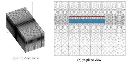
Figure 11:Finite element mesh of the surrounding fluid
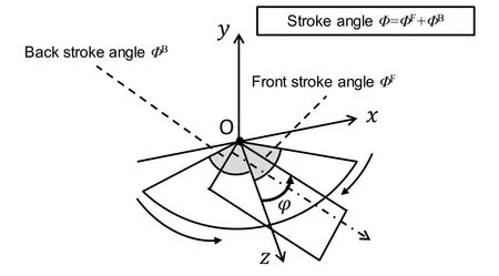
Figure 12:Control parameters for evaluating a pitching maneuver
5 Results and discussion
5.1 Rolling maneuver
Fig.13 shows the time histories of the aerodynamic force acting on the wing in theydirection,that is,the lift force,where the results are converted to the scale of the model insect using the dynamic similarity law.Noise in this figure is discussed in Appendix.As shown in this figure,the lift force increases as the stroke angle increases.This reason can be explained as described below.
Fig.14 shows the vorticity fields at the middle of the down-stroke,where the flapping translation has the maximum speed.As shown in this figure,the vorticity fields show element-by-element distributions near the model wing.This is because the interpolation characteristic of stabilized linear equal-order-interpolation velocity pressure elements used here [Tezduyar,Mittal,Ray et al.(1992)],that is,the vorticity is given by the derivative of the linearly interpolated velocity.The present setup for the domain size,the boundary condition,and the mesh size is almost equivalent to that in our previous studies [Ishihara,Horie and Niho (2014);Ishihara and Horie (2017)],and the present simulation program was carefully validated using the corresponding dynamically scaled experiments in these studies.The resolution of the fluid mesh is enough to compute the fluid surface force acting on the wing.A leading-edge vortex was formed by the flapping translation of the wing.As shown in this figure,the magnitude of the vorticity increases as the stroke angle increases.This is because the maximum flapping speed increases as the stroke angle increases under the constant flapping period.The leading-edge vortex makes a significant contribution to the lift force generation [Dickinson,Lehmann and Sane (1990)].Therefore,the lift force increases as the stroke angle increases.
The roll torque acting on the body can be obtained using Fig.13.Fig.15 shows the time histories of the roll torque in the case ofa=L/4,where the left wing’s stroke angleΦLwas changed from 88° to 123°,while the right wing’s stroke angleΦRwas fixed to 123°.Furthermore,the relationships betweenΦLand the mean lift forces are obtained as shown in Fig.16 by taking the average of each torque history.As shown in Fig.16,the relationships betweenΦLand the mean roll torque are approximately linear.The anticlockwise rotation about thex-axis,that is,a positive roll,will be caused,because the mean torque is always positive.The mean roll torque increases as the body radiusaincreases for eachΦLbecause the roll torque is proportional to the body radius.In the inertial momentJx(17),the second term in the right-hand side is proportional to the square of the body radius,but its effect on the total magnitude is not significant,because of the existence of the constant first term.Therefore,the effect of the body radius on the roll angle is not significant;that is,the ranges of the roll angle fora=L/6,L/4,andL/2 are not so different from each other.
The rolling behavior of the body can be simulated using the roll torque histories.The time histories of the roll angle in the cases ofa=L/6,L/4,andL/2 are shown in Figs.17,18,and 19,respectively,where a positive roll is always caused as predicted in the discussion of Fig.16.As shown in these figures,a larger roll angle is generated by the larger difference of the stroke angle between the right and left wings.The roll angles at the time instant of 8 cycles from these figures are summarized in Tab.1.In actual observations of insects [Beatus,Guckenheimer and Cohen (2015)],the roll angle of 60° is produced during 8 strokes by the difference of stroke angles between the left and right wings,of which mean value is approximately 18°.In the present simulation,ΦL=105° corresponds to these observations,and the present results are comparable with the observed roll angle as shown in Tab.1.Especially,fora=L/4,which gives the moment of inertia of actual insects to the present cylinder model,the present result is 55°,which is close to 60° from the observations.It follows from these results that the proposed method can adequately simulate the rolling behavior of the insect flight maneuver.

Figure 13:Time histories of the lift force for various stroke angles
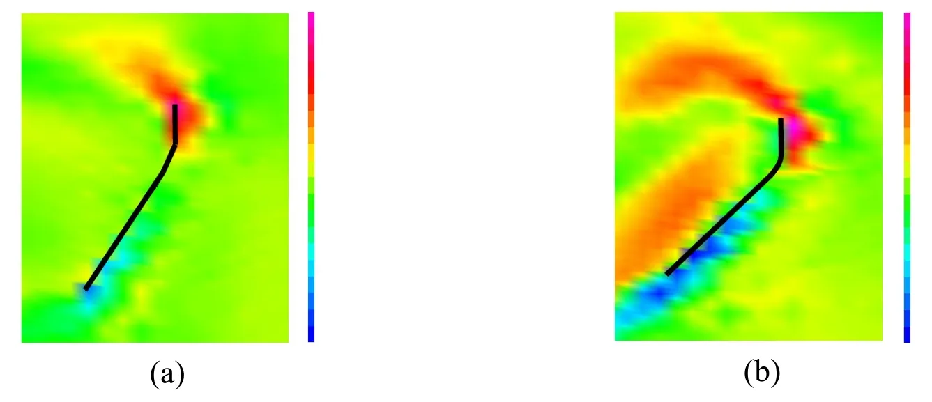
Figure 14:Vorticity fields near the wing chord at the middle of the down-stroke of 8th cycle (time instant of 8.125 cycles).The black bold line is the wing chord.The color contour shows the magnitude of the vorticity.(a)ΦL=88°.(b)ΦR=123°

Figure 15:Time histories of the roll torque for a=L/4
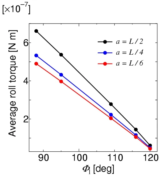
Figure 16:Relationships between the left wing’s stroke angle and mean roll torque for a=L/6,L /4,and L/2
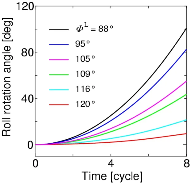
Figure 17:Time histories of the roll angle for a=L/6

Figure 18:Time histories of the roll angle for a=L/4

Figure 19:Time histories of the roll angle for a=L/2
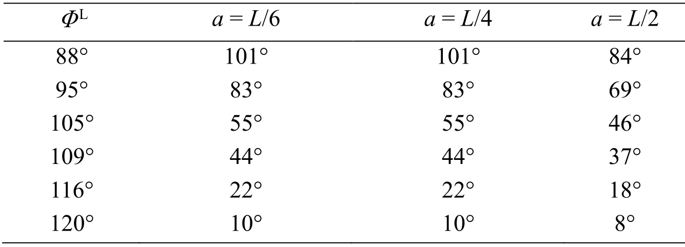
Table 1:Summary of the roll angles at the time instant of 8 cycles
5.2 Yawing maneuver
Fig.20 shows the time histories of the projected component of the aerodynamic force normal to the wing,that is,the drag force,where the results are converted to the scale of the model insect using the dynamic similarity law.As shown in this figure,the magnitude of the drag force decreases as the initial feathering angleθ0increases during the down stroke,while the magnitude of the drag force increases as the initial feathering angleθ0increases during the up-stroke.These relationships can be clearly observed by taking the average.Fig.21 shows these relationships,where the mean drag force during the downstroke decreases almost linearly asθ0increases,while the mean drag force during the upstroke increases almost linearly asθ0increases.The reason why these relationships appear can be explained as given below.
Fig.22 shows the time histories of the feathering angle,and Figs.23 and 24 show the wing chord motions during the down-stroke and up-stroke,respectively.We defineSpas the projection area of the wing chord normal to the translational direction.In the case ofθ0=0,the amplitudes ofSpduring the down-stroke and up-stroke are almost equal to each other because of the symmetricity of these half-stroke conditions.Furthermore,the amplitude ofSpin the case ofθ0>0 is smaller than that in the case ofθ0=0 during the down-stroke,as shown in Fig.23,while the amplitude ofSpin the case ofθ0>0 is larger than that in the case ofθ0=0 during the up-stroke,as shown in Fig.24.The dynamic pressure acting on the wing in the translational direction is proportional toSp.Therefore,as the initial feathering angleθ0increases,the magnitude of the drag force decreases during the down-stroke,while the magnitude of the drag force increases during the up-stroke.
Fig.25 shows the time histories of the yaw torque for the case ofa=L/4 as the right wing’s initial feathering angleθ0Ris changed,while the left wing’s initial feathering angleθ0Lis fixed at 0°.As shown in this figure,the magnitude of the yaw torque increases asθ0Rincreases.The mean value for each time history in this figure is indicated to show this more clearly.Fig.26 shows the relationships between the left wing’s stroke angle and the mean yaw torque fora=L/6,L/4,andL/2.As shown in this figure,the mean yaw torque increases asθ0Rincreases almost linearly.The anticlockwise rotation about they-axis,that is positive yawing,will be caused because the mean torque is always positive.
The yawing behavior of the body can be simulated using the yaw torque histories.The time histories of the yaw angle fora=L/6,L/4,andL/2 are shown in Figs.27,28,and 29,respectively,where a positive yaw is always caused as predicted in the discussion of Fig.26.We further note that the magnitude of the yaw angle for eachθ0Rdecreases significantly as the body radius increases,irrespective of the increase of the magnitude of the yaw torque.This is because the inertial momentJy(18)is proportional to the square of the body radius.The yaw angles at the time instant of 18 strokes from these figures are summarized in Tab.2.In actual observations of insects [Bergou,Ristroph,Guckenheimer et al.(2010)],the yaw angle of 120° is produced during 18 strokes by the difference of feathering angles between the left and right wings,of which mean value is approximately 3°.In the present simulation,θ0R=3° corresponds to these observations,and the present results are comparable with the observed yaw angle as shown in Tab.2.Especially,fora=L/4,which gives the moment of inertia of actual insects to the present cylinder model,the present result is 142°,which is close to 120° from the observations.It follows from these results that the proposed method can adequately simulate the yawing behavior of the insect flight maneuver.
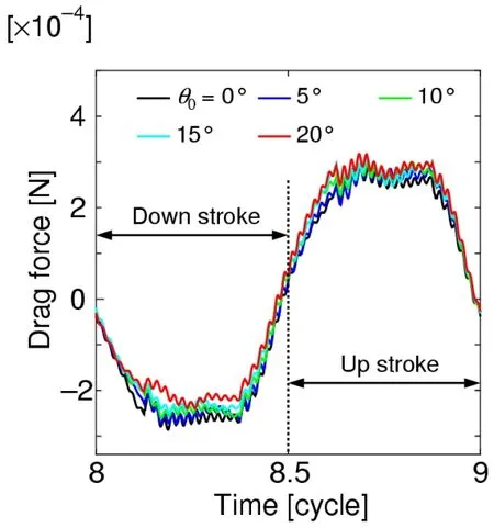
Figure 20:Time histories of the drag force for various initial feathering angles
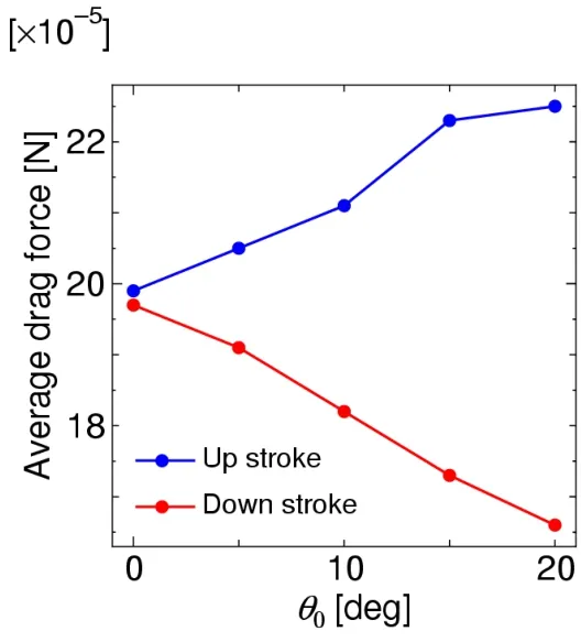
Figure 21:Relationships between the initial feathering angle and the mean drag
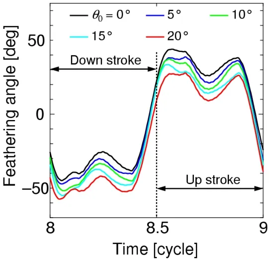
Figure 22:Time histories of the feathering angle for the various initial feathering angles
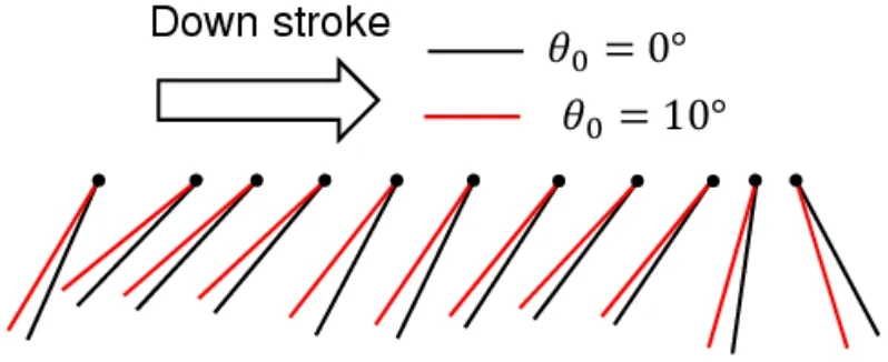
Figure 23:Wing chord motion during the down-stroke.The black lines show the wing chord for θ0=0°,while the red lines show the wing chord for θ0=10°.The black circles indicate the leading edge.Each chord moves from left to right

Figure 24:Wing chord motion during the up-stroke.The black lines show the wing chord for θ0=0°,while the red lines show the wing chord for θ0=10°.The black circles indicate the leading edge.Each chord moves from right to left

Figure 25:Time histories of the yaw torque for a=L/4

Figure 26:Relationships between the left wing’s initial feathering angle and mean yaw torque for a=L/6,L /4,and L /2
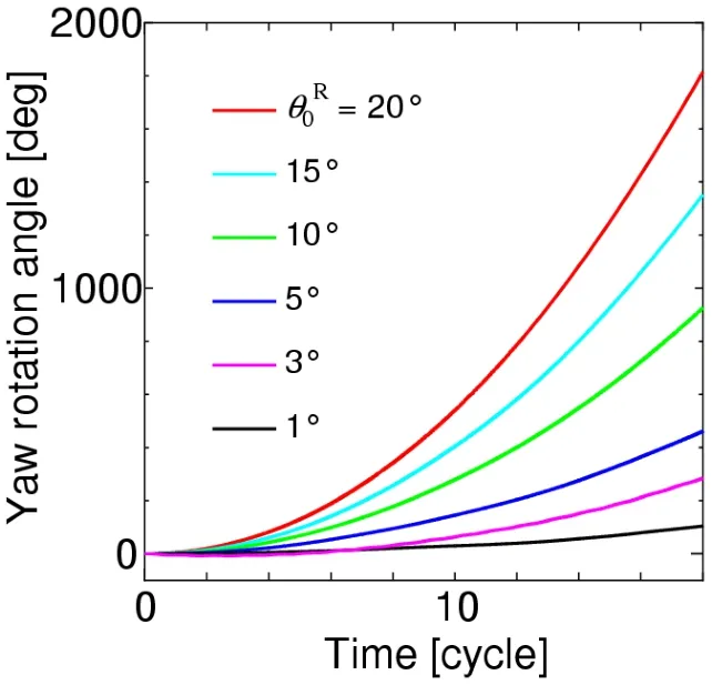
Figure 27:Time histories of the yaw angle for a=L/6

Figure 28:Time histories of the yaw angle for a=L/4
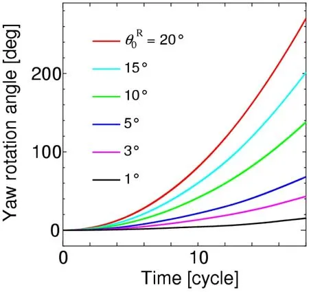
Figure 29:Time histories of the yaw angle for a=L/2
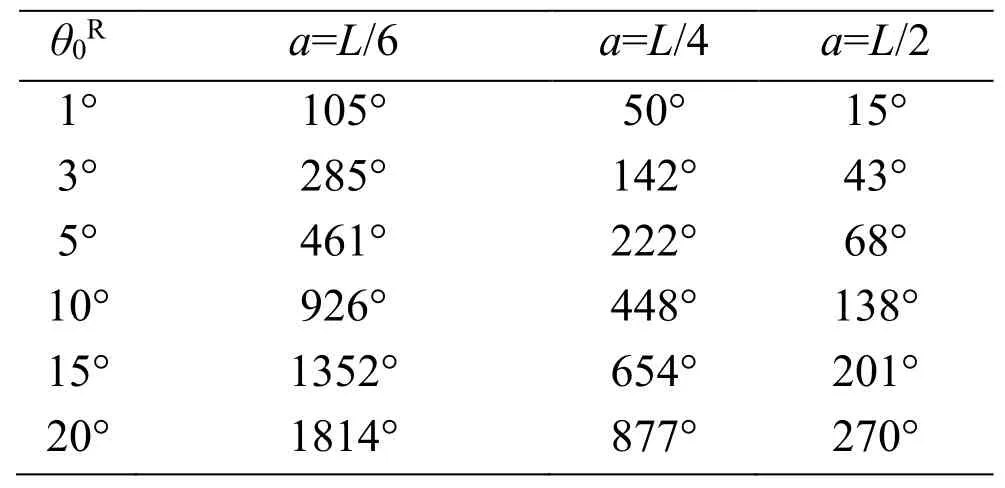
Table 2:Summary of the yaw angles at the time instant of 18 cycles
5.3 Pitching maneuver
Fig.30 shows the time histories of the pitch torque as ΔΦis changed,and Fig.31 shows the relationship between ΔΦand the mean pitch torque.As shown in these figures,the mean pitch torque is always positive,and its magnitude increases as ΔΦincreases.These results can be explained as described below.
The lift force during the front-stroke angleΦFcauses a pitch-up torque,as shown in Fig.32 (a),while the lift force during the back-stroke angleΦBcauses a pitch-down torque,as shown in Fig.32 (b).Therefore,the pitch torque or the difference between the pitch-up torque and pitch-down torque is positive in the case of ΔΦ=ΦF-ΦB>0,and it increases as ΔΦincreases.
The pitching behavior of the body can be simulated using the pitch torque histories.The time histories of the pitch angle fora=L/6,L/4,andL/2 are shown in Figs.33,34,and 35,respectively,where a positive pitch is always induced,because the mean pitching torque is always positive,as shown in Fig.31.
The pitch angles at the time instant of 6 strokes from these figures are summarized in Tab.3.In actual observations of insects [Whitehead,Beatus,Canale et al.(2015)],the pitch angle of 23° is produced during 6 strokes by the deviation of the front-stroke angles,of which mean value is approximately 16°.In the present simulation,ΔΦ=15° correspond to these observations,and the present results are comparable with the observed pitch angle as shown in Tab.3.Especially,fora=L/4,which gives the moment of inertia of actual insects to the present cylinder model,the present result is 15°,which is close to 23° from the observations.It follows from these results that the proposed method can adequately simulate the pitching behavior of the insect flight maneuver.
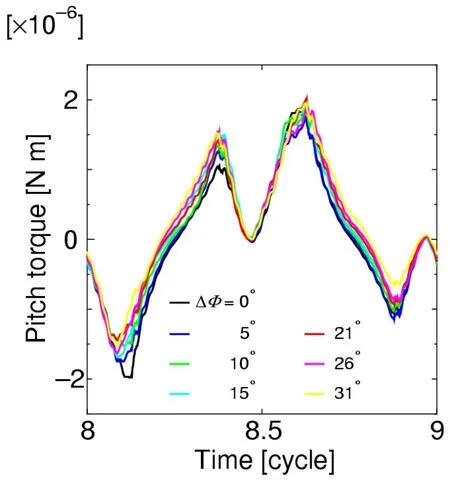
Figure 30:Time histories of the pitch torque for a=L/4

Figure 31:Relationships between ΔΦ and mean pitch torque for a=L /4

Figure 32:Schematics of the mechanism of pitch torque generation.The straight arrows indicate the total lift force acting on the wing,and the circular arrows indicate the resulting pitch torque.(a)Pitch-up torque during front-stroke angle ΦF.(b)Pitch-down torque during back-stroke angle ΦB
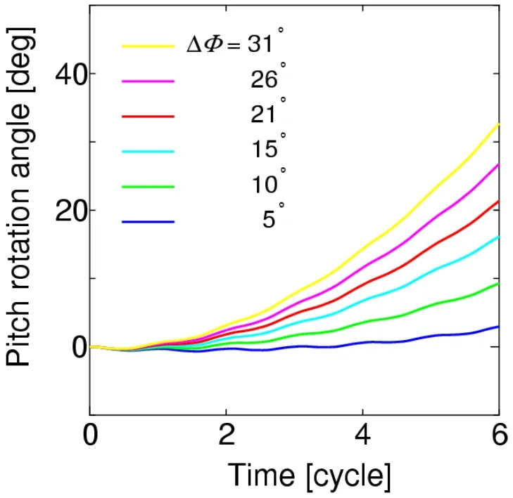
Figure 33:Time histories of the pitch angle for a=L/6

Figure 34:Time histories of the pitch angle for a=L/4
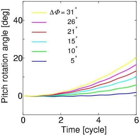
Figure 35:Time histories of the pitch angle for a = L/2
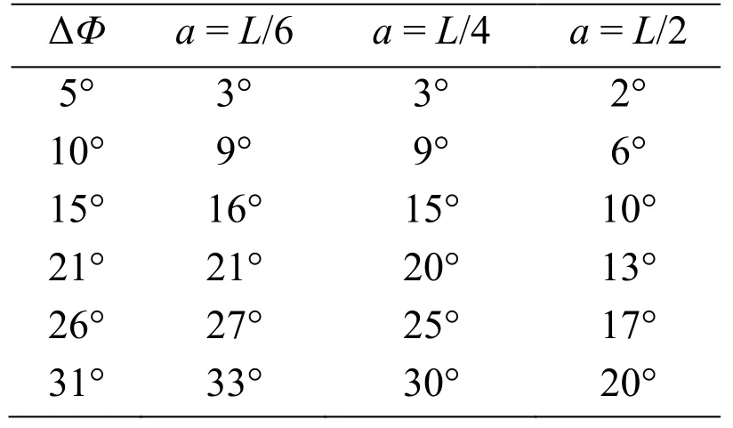
Table 3:Summary of the pitch angles at the time instant of 6 cycles
6 Concluding remarks
In this study,the partitioned method was proposed to analyze maneuvering during insect flapping flight.In the proposed method,insect flapping flight is decomposed into wing and body subsystems,and they are coupled via boundary conditions imposed on the wing’s base.For the wing subsystem,the finite element method was selected to accurately analyze the strong coupling between the wing and the surrounding fluid because of the high flexibility of the wing.For the body subsystem,in contrast,rigid body motion was analyzed because the elastic deformation of the body is far smaller,and rotations from the static state are considered as the maneuver.One-way coupling was used as the partitioned algorithm for the purpose of checking the fundamental validity of the proposed method.The use of one-way coupling can also be justified by the physical interpretation of the maneuver,that is,rotations from the quasi-static state.The fundamental maneuvers during insect flapping flight are rolling,yawing,and pitching.These were simulated using the proposed method to obtain the following results:
In the rolling simulation,roll torque was caused by the difference of the stroke angle between the right and left wings.In the yawing simulation,yaw torque was caused by the initial feathering angle in the right wing only.In the pitching simulation,the pitch torque is caused by the difference of the front and back stroke angles in both the right and left wings.All maneuvering motions were comparable to those seen in observations of actual insects.
These results demonstrate that the proposed method can adequately simulate the fundamental maneuvers of insect flapping flight.Furthermore,the maneuvering mechanisms could be investigated and demonstrated using the proposed method at the governing equation level,which might be difficult using other approaches.Therefore,the proposed method will contribute to revealing the underlying insect flight mechanisms.
Acknowledgement:This work was supported by the Japan Society for the Promotion of Science,KAKENHI Grant No.17H02830.
Appendix
Noise can be observed in the force time histories such as Fig.25.Fig.A1 shows an example of their spectral analysis results,which are converted to the scale of the insect using the dynamic similarity law.In this figure,noise observed in the force time histories appears as the amplitudes from 2,000 Hz to 2,500 Hz.The frequency of this noise is very close to the natural frequency of the sixth order mode vibration of the wing,which is given by the finite element mode analysis.Fig.A2 shows the shape of this mode.As shown in this figure,it is similar to the shape of the first order mode,that is,the feathering mode.Therefore,the sixth order mode vibration can appear following the feathering mode vibration.It follows from these results and discussion that the source of this noise is considered as the sixth order mode vibration of the wing.The magnitude of the sixth order mode vibration is much smaller than that of the feathering mode vibration.This is because the natural frequency of the sixth order mode vibration is much higher than the flapping frequency,while that of the feathering mode vibration is close to the flapping frequency.The feathering mode vibration is dominant in the aerodynamic force generation [Ishihara,Horie and Niho (2014);Ishihara and Horie (2016)].Therefore,this noise does not have a significant effect on the results.

Figure A1:Spectral analysis result for the time history of the yaw torque
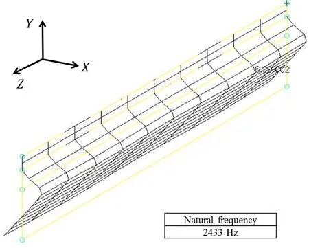
Figure A2:Shape of the sixth order mode of the present model wing
杂志排行
Computer Modeling In Engineering&Sciences的其它文章
- Forced Vibration of the Non-Homogeneously Pre-Stressed System Consisting of the Hollow Cylinder and Surrounding Medium
- Dynamic Analyses of a Simply Supported Double-Beam System Subject to a Moving Mass with Fourier Transform Technique
- Numerical Study of Trapped Solid Particles Displacement From the Elbow of an Inclined Oil Pipeline
- Analytical and Numerical Solutions of Riesz Space Fractional Advection-Dispersion Equations with Delay
- 3-D Thermo-Stress Field in Laminated Cylindrical Shells
- Seismic Fragility Analysis of Long-Span Bridge System with Durability Degradation
