Numerical Analysis of Tilted Cutting and F128 Brushes
2019-11-26LibardoVanegasUsecheMagdAbdelWahabandGrahamParker
Libardo V.Vanegas-Useche ,Magd M.Abdel-Wahab and Graham A.Parker
Abstract: Road sweeping is an essential service that has to be conducted for public health,as well as aesthetic purposes.In many countries,sweeping vehicles are used for this activity.They usually comprise a gutter brush that sweeps the debris that is located in the road gutter.This work studies the performance of two kinds of gutter brushes:a cutting brush and a flicking (F128)brush.This is carried out by means of a 3-D dynamic,nonlinear Finite Element (FE)brush model developed by the authors.In this model,inertia forces are applied to the bristle,and its clamped end is fixed.Consequently,the surface (road)is rotated,translated,and raised.Bristle-road interaction is modelled as flexible-to-rigid contact.In particular,the aim of this article is to compare the performance of a conventional brush and a brush rotating at variable speed.As brushes normally work tilted,FE analyses are carried out for tilted cutting and F128 brushes,rotating at speeds that fluctuate at different frequencies.It is concluded that brush oscillations have a significant effect on bristle tip velocities and bristle-road forces.Also,at certain frequencies,oscillations seem to improve sweeping performance of the F128 brush.However,they do not appear to improve significantly the performance of the cutting brush.
Keywords: Gutter brushes,cutting brush,flicking brush,FEM,variable speed,brushing.
1 Introduction
Street sweeping is an indispensable service in our cities,both for aesthetic purposes and for public hygiene [Vanegas-Useche,Abdel-Wahab and Parker (2018)].Also,it is an important part of solid waste management systems [Bartolozzi,Baldereschi,Daddi et al.(2018)].Due to its importance,research has been conducted on aspects such as environmental impact and pollution [Bartolozzi,Baldereschi,Daddi et al.(2018)],maintenance of pavement surfaces [Winston,Al-Rubaei,Blecken et al.(2016)],and street sweeping routing [Golden,Nossack,Pesch et al.(2017)].When this activity is performed adequately,it tends to be unnoticed;however,it attracts the attention of the citizens when performed ineffectively [Peel and Parker (2002)].
This public service is sometimes provided by means of lorry-type sweeping vehicles.These sweepers usually consist of a vacuum unit,a wide broom,and a gutter brush.Particularly,the gutter brush plays an important role,as most of the debris on the streets lie in the road gutter [Peel (2002)].
Fig.1 depicts two commercial gutter brushes for street sweeping:a cutting brush and a flicking brush (more precisely,the flicking brush is named here F128 brush).These brushes have been used for testing in previous works [Vanegas-Useche,Abdel-Wahab and Parker (2010);Vanegas-Useche,Abdel-Wahab and Parker (2015b)].They comprise steel bristles with rectangular cross sections,which are orientated with different bristle mount orientation angles,γ.In the cutting brush,the bristle cross section is orientated (withγ=0)so that it tends to produce a stiff bristle-debris collision,cutting through debris.Conversely,the orientation of the bristles of an F128 brush corresponds to a mount orientation angle ofγ=128° (measured relative to the orientation of the cutting brush).Because of this orientation,the bristles tend to deflect opposite to the bristle tip travel direction and make more contact with the debris.
Although gutter brushes play an important role in sweeping vehicles,published research on them is scarce.Research started about twenty years ago at Surrey University.Peel et al.[Peel,Michielen and Parker (2001);Peel (2002)],and Peel et al.[Peel and Parker (2002)] worked on two main aspects:automation of the sweeping process and mathematical static models for cutting and flicking brushes.Regarding automation,the objective was to improve performance and safety,as well as to reduce brush wear,vehicle emissions,and driver fatigue.The proposed control of the sweeper includes identification of road and debris conditions and adaptation of the brushing parameters to the sweeping conditions.
As for the analytical models,an understanding of the geometric and kinetic characteristics of gutter brushes was gained:brush vertical force,brush torque,and bristle deformation were studied.These models were validated through experimental tests,using a gantry test rig that consists of several commercial gutter brushes,an asphalt test road,and a device for setting up and driving the brushes.Afterwards,analytical models for oscillatory cutting and flicking brushes in free flight were developed in previous works [Vanegas-Useche,Abdel-Wahab and Parker (2007);Vanegas-Useche,Abdel-Wahab and Parker (2008a)].Also,Wang et al.[Wang,Sun,Abdel-Wahab et al.(2015)] developed a regression model,based on FE and experimental results,that may be used in a real time scenario.
Improved models (Finite Element (FE)models)were then developed.Firstly,static FE models were developed to gain an enhanced understanding of the dynamic behaviour of gutter brushes [Wang (2005);Abdel-Wahab,Parker and Wang (2007);Abdel-Wahab,Wang,Vanegas-Useche et al.(2010)].Secondly,dynamic FE models were developed by the authors to study the new concept of brushes rotating at variable speed (oscillatory brushes);one of these models was used to study the performance of horizontal F128 brushes [Vanegas-Useche,Abdel-Wahab and Parker (2011a)].A horizontal brush is a brush whose mounting board is parallel to the road surface.
Additionally,experimental research was performed to determine the behaviour of oscillatory gutter brushes [Vanegas-Useche,Abdel-Wahab and Parker (2008b)] and the efficiency of cutting and F128 brushes rotating at constant speed [Vanegas-Useche,Abdel-Wahab and Parker (2010);Abdel-Wahab,Wang,Vanegas-Useche et al.(2011)] and variable speed [Vanegas-Useche,Abdel-Wahab and Parker (2015b)],for different debris types.These tests were carried out using the gantry test rig mentioned previously.Similarly,research has also been conducted on other types of brushes;however,this research is also limited.Fitzpatrick et al.[Fitzpatrick and Paul (1987);Shia,Stango and Heinrich (1989);Stango,Heinrich and Shia (1989);Stango,Cariapa,Prasad et al.(1991);Heinrich,Stango and Shia (1991);Stango and Shia (1997)] have studied the behaviour or performance of brushes for surface finishing operations.Holm et al.[Holm,Haslbeck and Horinek (2003)] have studied brushes for surface fouling removal.Holopainen et al.[Holopainen and Salonen (2002);Holopainen and Salonen (2004)] have carried out research on brushes for cleaning air ducts.Moumen and Busnaina [Moumen and Busnaina (2001)],Philipossian et [Philipossian al.and Mustapha (2003)],Huang et al.[Huang,Guo,Lu et al.(2011)],Sun et al.[Sun,Zhuang,Li et al.(2012);Sun,Han and Keswani (2017)] have dealt with brushes for post-CMP (Chemical Mechanical Planarization)cleaning.Shehri et al.[Shehri,Parrott,Carrasco et al.(2016)] and Parrott et al.[Parrott,Carrasco Zanini,Shehri et al.(2018)] have studied solar panel cleaning.For the reader interested,literature reviews on brushing technology and street sweeping are provided in previous works [Vanegas-Useche,Abdel-Wahab and Parker (2010);Vanegas-Useche,Abdel-Wahab and Parker (2011a);Vanegas-Useche,Abdel-Wahab and Parker (2015b)].
In this article,the dynamic behaviour and performance of tilted oscillatory cutting and F128 brushes are investigated by means of the FE model developed by Vanegas-Useche et al.[Vanegas-Useche,Abdel-Wahab and Parker (2011a)];a tilted brush is that whose mounting board is not parallel to the road surface,as occurs in the sweeping practice.To the best knowledge of the authors,this FE model is the only dynamic (time-history)model that has been developed for gutter brushes for street sweeping.Contrary to Vanegas-Useche et al.[Vanegas-Useche,Abdel-Wahab and Parker (2011a)],who study the performance of horizontally constrained gutter brushes,this paper considers a tilted brush.The objective is to evaluate the effects of brush oscillations during a normal sweeping operation.Therefore,this work presents original results oftiltedgutter brushes.Its novelty consists of determining the behaviour of oscillatory tilted gutter brushes,obtained through FE modelling.These results enable to ascertain whether brush oscillations may improve sweeping performance.
2 Methodology
2.1 Geometry and configuration of the brushes
The dynamic FE model developed can be employed for studying different brush types (e.g.,circular brushes,cup brushes for cleaning operations,and gutter brushes).In this work,cutting and F128 brushes for street sweeping with the characteristics provided in Tab.1 are studied.
The brush modelled consists of one row of 24 clusters,each of these with 60 bristles.The bristles are made of steel,whose density (ρ)and elastic constants:Young’s modulus (E)and Poisson ratio (ν)are provided in Tab.1.They are of rectangular cross section,whose dimensions aret1(breadth)andt2(width)(Fig.1(a)).The bristle mount orientation angle (γ),which was explained in Section 1,is the angle that defines the action of the brush:cutting or flicking action.The bristle mount angle (φ),bristle mount radii (rA1yrA2),and bristle length (lb)are illustrated in Fig.1;the bristle mount angle is the one between the bristle axis and the brush axis.In order to orientate the brush appropriately towards the gutter,the brush is inclined the angle of attack (β)and rotated towards the kerb the brush offset angle (ξ),as shown in Fig.2.As may be inferred from the data in Tab.1,the angular speed of the brush (ω)varies between 90 and 110 rpm,which correspond to a mean value ofωof 100 rpm and an alternating value of 10 rpm.The brush translational speed corresponds to the vehicle speed (v).Brush penetration (Δ)corresponds to the vertical distance that the brush is lowered after first bristle contact.The values in Tab.1 are values of commercial brushes and typical brush configurations.

Table 1:Gutter brush geometric and operating parameters and bristle material properties
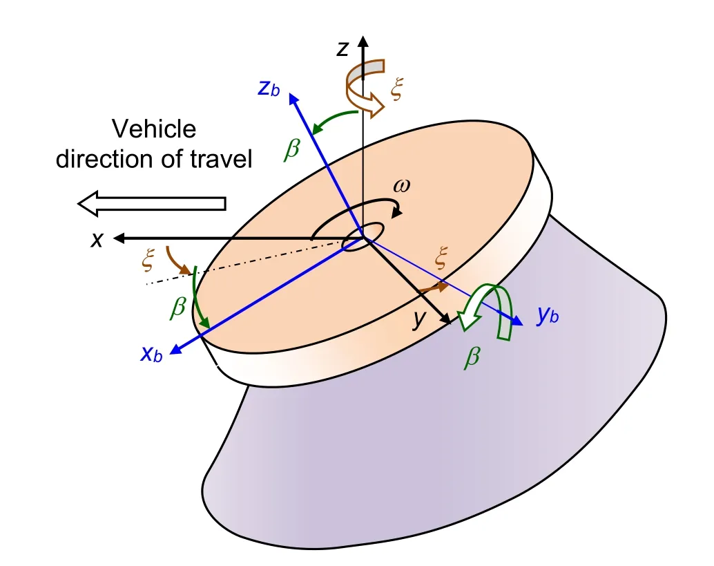
Figure 2:Brush offset angle and brush angle of attack
2.2 Description of the FE model
Modelling a gutter brush in a precise manner is a very complex task,as its bristles are typically of different lengths,are not completely straight,and have different mount orientation angles and mount angles.Also,there is a variety of debris and road conditions and complex interactions among bristles,road,and debris [Vanegas-Useche,Abdel-Wahab and Parker (2011a)].Consequently,it is appropriate to make simplifying assumptions in order to model the sweeping process.
The main assumptions of the FE model [Vanegas-Useche,Abdel-Wahab and Parker (2011a)] are as follows.
● The bristles are clamped rigidly into the mounting board,are mounted in an orderly manner,and do not interact with bristles of other clusters.The interaction among bristles of a given cluster is partially taken into account by modelling damping,as described later.
● The surface of the road is flat and free from debris,and its deformations are negligible when compared to bristle deformations.
● The behaviour of a cluster is represented by the behaviour of a single bristle.
The results of previous research [Peel (2002);Wang (2005);Abdel-Wahab,Parker and Wang (2007)] indicate that the assumptions made are practical.
The brush model [Vanegas-Useche,Abdel-Wahab and Parker (2011a)] was developed in ANSYS®.It is a 3-D transient (time-history)structural model that involves large deflection and contact,which are highly non-linear.A transient dynamic analysis was performed,as the loads and displacements of the bristles of an oscillatory gutter brush vary with time.
A structural problem is a second-order system in time,whose equation of motion is:

wheremis mass,cis viscous damping,kis the stiffness,Fais the applied force,andu(t)is the displacement.
As the model is a multiple degree of freedom (DOF)system (as will be described later,it has 17 nodes,each one with 6 DOF),the dynamic equilibrium equation in the transient dynamic analysis is:

where M,C,and K are the mass,damping,and stiffness matrices,respectively;{u} ,{} ,and {} are the nodal displacement,nodal velocity,and nodal acceleration vectors,respectively;and {Fa} is the applied load vector.The Newton Raphson approach is used for tackling non-linearities,and the Newmark integration method is used to solve the dynamic equilibrium equation.
The Newmark method utilises finite difference expansions in the time interval Δt;in this,it is assumed that [Ansys,Inc.(2018)]:


whereαandδare Newmark integration parameters,Δt=tn+1-tn,{un} is the nodal displacement vector at timetn,{} is the nodal velocity vector at timetn,{} is the nodal acceleration vector at timetn,{un+1} is the nodal displacement vector at timetn+1,{} is the nodal velocity vector at timetn+1,{} is the nodal acceleration vector at timetn+1.
As the primary aim is to compute the displacement vector {un+1},Eq.(1)is evaluated at timetn+1as follows:

The solution for {un+1} is calculated by first rearranging Eq.(3)and Eq.(4),as follows:

where


After a solution for the displacement {un+1} is determined,velocities and accelerations are updated through Eq.(7)and Eq.(6).
The solution of Eq.(5)through the use of Eq.(3)and Eq.(4)is unconditionally stable for:

These Newmark parameters are related to the input as follows [ANSYS,Inc.(2018)]:

whereγis the amplitude decay factor,whose default value is 0.005.Further details of this Newmark procedure to solve the equation of motion is provided in the ANSYS Theory [ANSYS,Inc.(2018)].
As bristle internal friction and the friction among bristles within a cluster produce a damped motion,damping is taken into account and modelled as Rayleigh damping,which is a form of viscous damping.In this type of damping,the damping matrix is the sum of two terms:the stiffness matrix times its multiplierβDand the mass matrix times its multiplierαD:

Experimental tests on clusters of gutter brushes [Vanegas-Useche,Abdel-Wahab and Parker (2015a)] indicate that appropriate values of the Rayleigh damping coefficients are:stiffness matrix multiplier for damping,βD= 0.4 ms,and mass matrix multiplier for damping,αD= 3 s-1.
Regarding bristle-surface contact modelling,it comprises two “springs” that provide a normal and a tangential contact force.The normal force is linked to a normal contact stiffness (Kn)and the tangential (friction)force is linked to a tangential contact stiffness (Kt),which is proportional to the coefficient of friction (µ)andKn.These parameters are required by the contact algorithms pure penalty method and augmented Lagrangian method.Therefore,it is necessary to define the values ofKn,µ,andKt.The value ofKnis taken as 2 MN/m,which was determined in a previous work by comparing FE and experimental results,for the interaction between a carbon steel bristle and a concrete road surface [Vanegas-Useche,Abdel-Wahab and Parker (2018)].
As for bristle-surface friction,the exponential friction model is employed:
whereµis the friction coefficient andµkandµsare the kinetic and static friction coefficients,respectively;eis Euler’s number,vsis the sliding speed andcvis the decay coefficient.Based on the results of a previous work [Vanegas-Useche,Abdel-Wahab and Parker (2011b)],appropriate values may beµs=0.70,µk=0.27,andcv=0.40 s/m,for the cutting brush,andµs=0.83,µk=0.40,andcv=0.87 s/m,for the F128 brush;these values were found by comparing the results of the FE model developed and data from experimental tests performed with gutter brushes rotating at three speeds:60,100,and 140 rpm.
Regarding the element type,the brush is modelled by a bristle with sixteen nonlinear beams (ANSYS® BEAM189 element).Fig.3 illustrates the beam element “BEAM189,” which is a 3-D quadratic (3-node)finite strain beam.The element is limited by two end nodes “i” and “j,” and has a midside node “k.” It also has an optional “l” node,which is used to indicate the orientation of the cross section of the beam.This element is based on Timoshenko beam theory (first-order shear-deformation theory)and is suitable for analysing slender to moderately stubby beams.It has 6 or 7 degrees of freedom at each node (three translations,three rotations,and an optional warping magnitude).BEAM189 is suitable for nonlinear,large rotation analysis and includes stress stiffness terms.

Figure 3:Beam element with 3 nodes and an optional orientation node
As the bristles of gutter brushes are subjected to large deformations and road deformations are insignificant,the interaction between the tip of the bristle and the surface of the road is modelled by a flexible contact element (CONTA175,3-D node-tosurface contact element)attached to the tip and a rigid target element (TARGE170,3-D target element)attached to the road areas;the surface is represented by flat areas (no finite elements are needed).Bristle-road contact is modelled through the augmented Lagrangian method.
In the FE model,the rotation of the brush is modelled through inertia loads,and the clamped end of the bristle is rigidly constrained.Consequently,the surface is rotated,translated,and raised.The required inertia loads on the bristle are gravity (withg=9.8066 m/s2)and centrifugal,tangential,and Coriolis forces,which are applied through available ANSYS commands.In order to achieve the desired accuracy,sensitivity analyses were performed [Vanegas-Useche,Abdel-Wahab and Parker (2018);Vanegas-Useche,Abdel-Wahab and Parker (2011a)].The results of these analyses indicate that appropriate values of the time step,which is used for applying loads and boundary conditions,is 0.1 ms,and of the substep or integration time step is 5 µs.
For studying the behaviour of oscillatory cutting and F128 brushes,an angular velocity function,ω(t),and the corresponding angular acceleration function,α(t),have to be selected (tis time).In this work,the VAP function,which is a mathematical function that was developed by the authors to reduce the accelerations of the brush,is selected [Vanegas-Useche,Abdel-Wahab and Parker (2007)]:

whereωmandωaare the mean and alternating components ofω(t),fis the frequency ofω(t),and


where the function “int” rounds the argument down to the nearest integer.
The VAP formulation is function of thesmoothness parameter b.This parameter belongs to the open interval (0,1).However,it should be close to zero for minimising brush shaft accelerations.The value selected isb=0.05.
Fig.4 illustrates the VAP function forb≈0 andb=0.10.Whenb≈0,ω(t)is a triangle function andα(t)is a square function,and the maximum brush angular acceleration is minimised.However,the torque in the brush shaft exhibits abrupt changes.

Figure 4:VAP angular speed and acceleration vs.time
Before reaching the nominal angular velocity shown in Fig.4,it is necessary to accelerate the brush from rest;therefore,there is a need for an initial transient stage.The brush is accelerated from rest,att=0,up to the nominal rotational speed,att=0.1 s.The nominal penetration of the brush is applied att=0 (as the brush is tilted,the initial position of the bristle may be conveniently selected so that it starts in free flight and then contacts the surface).A large number of analyses were performed in order to investigate the behaviour of conventional and oscillatory brushes.A number of brush frequencies,in the interval [0,50 Hz],are studied.
The simulation time is selected so that the bristle makes contact with the road surface three times.The first contact occurs during the start-up of the brush;thus,this stage is not analysed.The subsequent contacts (second and third)are analysed and are used to confirm the repeatability of bristle dynamic behaviour.The parameters of interest are determined for these two contact periods,and the average of both values is taken.
During the second and third contacts,the time intervals that are of importance are those during which the bristle is inside the sweeping zone (this is the zone of the gutter the brush has to cover,as the rest of the road is swept by a wide broom or a suction unit).The sweeping zone widths are 30 cm and 33 cm for the F128 and cutting brush,respectively.For the F128 brush,the approximate intervals [0.66 s,0.94 s] and [1.26 s,1.54 s] correspond to bristle-road contact,and [0.52 s,0.94 s] and [1.12 s,1.54 s],to bristle tip riding over the sweeping zone.For the cutting brush,they are [0.65 s,1.00 s] and [1.25 s,1.60 s],for bristle-road contact,and [0.62 s,0.94 s] and [1.22 s,1.54 s],for tip riding over the sweeping zone.These figures show that,for the F128 brush,the actual sweeping zone practically coincides with the practical zone.For the cutting brush,contact extends outside the practical sweeping zone,but,there,the contact tends to be intermittent.The time intervals selected to assess brush performance are [0.66 s,0.94 s] and [1.26 s,1.54 s],for the F128 brush,and [0.65 s,0.94 s] and [1.25 s,1.54 s],for the cutting brush.In these intervals,the bristle tip is over the practical sweeping zone and in contact with or very close to the surface.
The description of the FE brush model,provided previously,corresponds to its basic characteristics.However,a comprehensive description of the model is given in Vanegas-Useche et al.[Vanegas-Useche,Abdel-Wahab and Parker (2011a)].
Lastly,sweeping effectiveness is assessed through some performance criteria.These were defined in Vanegas-Useche et al.[Vanegas-Useche,Abdel-Wahab and Parker (2011a)] and are used to estimate the frequencies of brush oscillations that may provide a high performance.The criteria were formulated taking into account debris removal mechanisms [Vanegas-Useche,Abdel-Wahab and Parker (2011a)].
For a certain brush configuration,it is assumed that [Vanegas-Useche,Abdel-Wahab and Parker (2011a)]:
(a)Effectiveness is higher when thework of the bristle-road friction force,WFf,is larger.
(b)Effectiveness is higher when themaximum bristle-road friction force,Ff max,is higher (a short-duration large friction force may dislodge compacted debris,and smaller forces may then be necessary to remove the dislodged debris).
(c)Effectiveness is higher when the“intensity” of the bristle-road friction force,IFf,is greater.The parameterIFfis defined as the area under the friction force-tip displacement curve,but above the lineFf=Ffe,whereFfis the magnitude of the bristle-road friction force andFfeis the equivalent force that would produce the same work as its counterpart of the actual force.IFfis given by

wheresxyis the bristle tip position,measured along its path on the plane of the surface,Δsxyis the total distance covered by the tip,and the function 〈〉 takes the value of the argument if this is positive and takes zero if it is negative.Fig.5 presents an example that illustrates the definition ofIFf;it is represented by the sum of the shaded areas.

Figure 5:Definition of the intensity of the friction force
(d)Effectiveness increases with thearea under the curvevtip2-t(and with the average ofvtip2,),wherevtipis the magnitude of the tip velocity andtis time.The square of the tip velocity is utilised,as the accelerations,forces,and kinetic energy that may be transferred to the debris tend to be proportional to it.
(e)Effectiveness is higher when themaximum value of vtip2(vtip max2)is greater.
(f)Effectiveness is higher whenIv tip^2,the“intensity” of vtip2,is greater.A large bristle tip velocity tends to enhance dislodging of compacted debris,and then smaller velocities may be needed to sweep the debris.Fig.6 presents an example that illustrates the definition ofIv tip^2;this is defined as the area under the curvevtip2-t,but above the curvevtip(f=0)2-t,wherevtip(f=0)is the bristle tip velocity for a brush under the same conditions,excepting that the brush rotates at constant speed.The termIv tip^2corresponds to the sum of the shaded areas and is given by:
(g)Effectiveness is higher when thedirection of the velocity of the tipexhibits highfrequency variability.This is because high frequency changes of the direction ofvtipmay tend to sweep debris in different directions,which may improve debris removal.This criterion is quantified through the termωvtipxy,which is the rotational speed ofvtipon the plane of the surface.Taking into account that rotations ofvtipin any direction are assumed to be beneficial,absolute values are considered.Then,effectiveness tends to be higher when the average of the absolute values ofωvtipxy,is higher.However,whenvtip=0,the valueωvtipxyis taken equal to zero,as the tip will spin without sweeping.
These criteria are guidelines that have the aim of avoiding the modelling of debris,as this would greatly increase the modelling complexity.Nevertheless,future work may include debris modelling as a natural extension to the FE model.In addition,as road sweeping is a very complex dynamic process,a more accurate evaluation of the sweeping efficiency requires more complex models and more precise criteria.
3 Results and analysis for the F128 brush
3.1 Main results
Figs.7 and 8 introduce the main results of the analyses for the F128 brush.Contrary to the case of a horizontal F128 brush [Vanegas-Useche,Abdel-Wahab and Parker (2011a)],the curves exhibit no clear trends.However,most of the frequencies tend to increase bristle tip kinematics and contact forces (compared to a conventional brush,f=0).E.g.,the maximum and average values ofvtip2may be increased in 14% and 20%,respectively.

Figure 8:Force-related variables against brush frequency;F128 brush
Additionally,most of the frequencies seem to provide a value ofWFfthat is higher than that forf=0,with a maximum improvement of 11%.Moreover,for eleven frequencies,the maximum friction force is at least 940% higher than its counterpart of a conventional brush.This may improve dramatically the removal of compacted debris.From an analysis of the data in Figs.7 and 8,the maximum performance may be obtained whenf=25 Hz.However,due to the “random” nature of the behaviour exhibited,no definitive conclusion may be reached regarding a suitable value off.
3.2 Motion and velocity of the bristle tip
Some examples of the velocity patterns and the path followed by the bristle tip during the periods of contact are shown in Figs.9 and 10.As the analyses were performed so that the bristle makes contact with the surface two times under the nominal operating conditions of the brush,it is of interest to analyse the repeatability of brush characteristics.From all the results,including the example in Fig.9(a),it is inferred that the velocity characteristics are similar for the two contact periods studied.This implies that the period when the bristle is accelerated and penetrated up to when it achieves its nominal operating conditions does not affect significantly the results.

Figure 9:Tip velocity squared against time,for a set of frequencies;F128 brush
In Vanegas-Useche et al.[Vanegas-Useche,Abdel-Wahab and Parker (2011a)],it is shown that the characteristics of a horizontal F128 brush exhibit certain trends relative to the frequency of brush oscillation.In contrast,from all the results for a tilted F128 brush,it is observed that the paths and velocity curves exhibit similar patterns.In Fig.10(b),for instance,the frequencies that produce the minimum (f=12 Hz)and maximum (f=8 Hz)values ofare compared.It appears that there are no more significant variations of the direction of the velocity of the tip in one curve than in the other,even when analysing the paths more closely.The reason for this may be that the process of making contact,sliding,and loosing of contact of a tilted brush generates by itself,according to the results of the model,a significant amount of impacts and bristle vibrations.Hence,it could be argued that adding brush oscillations may not produce a large difference.However,brush oscillations indeed modify the paths and velocity patterns,as shown in Figs.9 and 10.This seems particularly true for low frequencies,maybe because the rotational speed of the brush remains for a longer time close to its maximum or minimum value.This tends to affect the tip velocity and path.
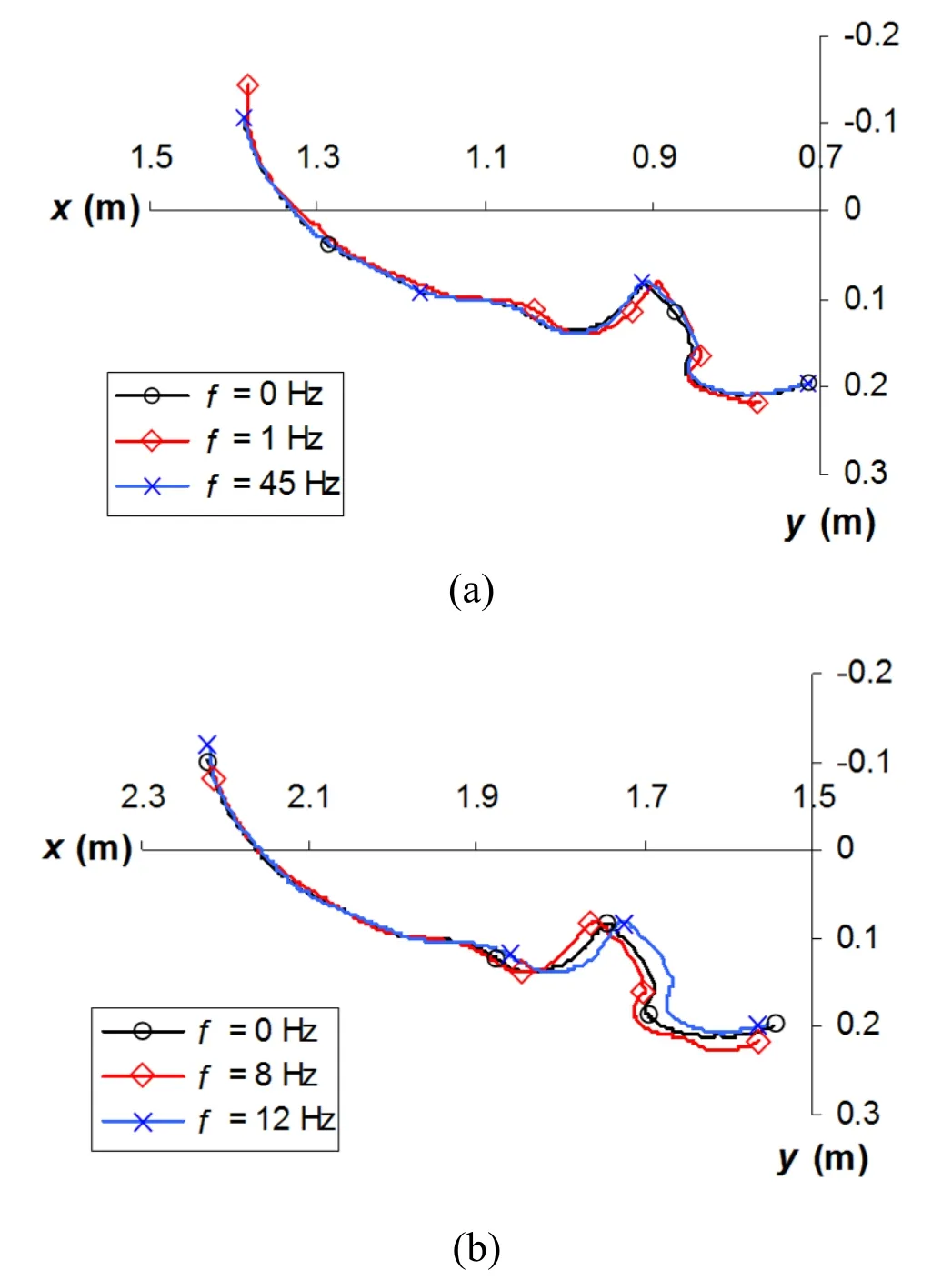
Figure 10:Path of the bristle tip,for a set of frequencies;F128 brush
3.3 Friction forces
Fig.11 presents some examples of curvesFf-sxy.These indicate that when the bristle first becomes in contact with the surface,the impact generates high contact forces.Then,due to the orientation of the bristle (γ=128°),it tends to deform outwards and forwards and eventually separates from the surface.Afterwards,the bristle contacts again the surface,deforming inwards and backwards,and the friction force becomes smaller and more stable.This behaviour is reflected in the paths shown in Fig.10.
As occurs with the kinematic behaviour,the friction forces tend to exhibit similar patterns for all the frequencies studied.In addition,the curves tend to be similar for the two contact periods of interest,as illustrated in Fig.10(a).However,Figs.8(a)to 8(c)show thatFfmaxand the work and intensity ofFftend to be larger than those of a conventional brush,for most of the frequencies.Very large differences occur in the case ofFfmax.
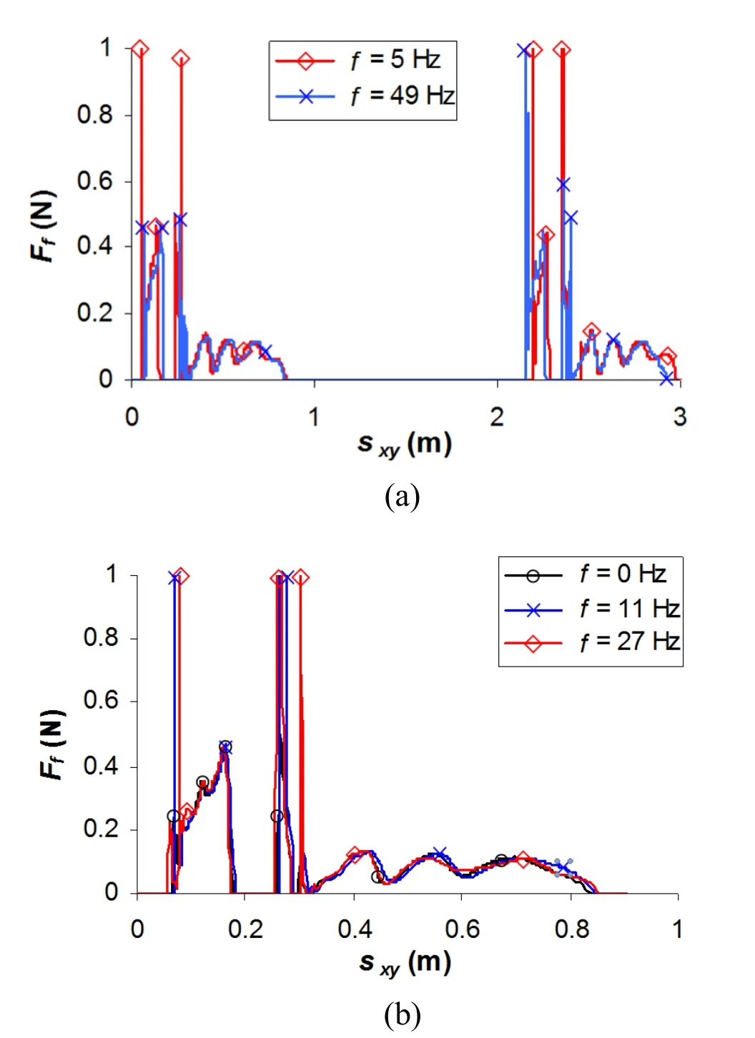
Figure 11:Friction force against tip displacement,for a set of frequencies;F128 brush
4 Results and analysis for the cutting brush
4.1 Main results
The main results for the cutting brush are provided by Figs.12 and 13.Similar to the F128 brush (Section 3),no obvious trends are exhibited.The results suggest that brush oscillations may improve or reduce performance,depending on the frequency.Of the frequencies studied,the maximum performance may be achieved whenf=29 Hz.However,the “randomness” of the results suggests that this statement may not be valid.Indeed,the stiff nature of the sweeping action of a cutting brush,along with the high dynamics of a tilted brush,generates high impact forces and bristle kinematics.Therefore,brush oscillations may not provide enhanced debris removal ability.
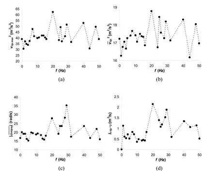
Figure 12:Kinematic variables against brush frequency;cutting brush
4.2 Motion and velocity of the bristle tip
Fig.14 shows some velocity curves for a number of brush frequencies.The differences in the curvesvtip2-tfor the various brush frequencies suggest that the amplitudes of oscillation of these curves,as well as the maximum and average tip velocities,may increase or decrease,depending onf;the curvesvtip2-tof the tilted cutting brush exhibit oscillations.An analysis of the results demonstrates that these variations are mainly due to bristle oscillations in the stronger plane (plane of the bristle cross-section about which the moment of inertia is higher),as oscillations in the weaker plane are small.These small tip oscillations are reflected by the small irregularities in the tip paths,as shown in Fig.15.The amplitude of oscillations of thevtip2-tcurve (and the bristle tip)increases as the tip approaches the boundary zone.This is partly caused by the increasing coefficient of friction as the velocity decreases.A comparison of the curves for both contact periods of interest suggests that the behaviour of the cutting brush tends to be more unpredictable.A reason for this is that the stiff cutting action and the dynamics of a tilted brush generate high velocities,accelerations,and forces,which make the process more variable.
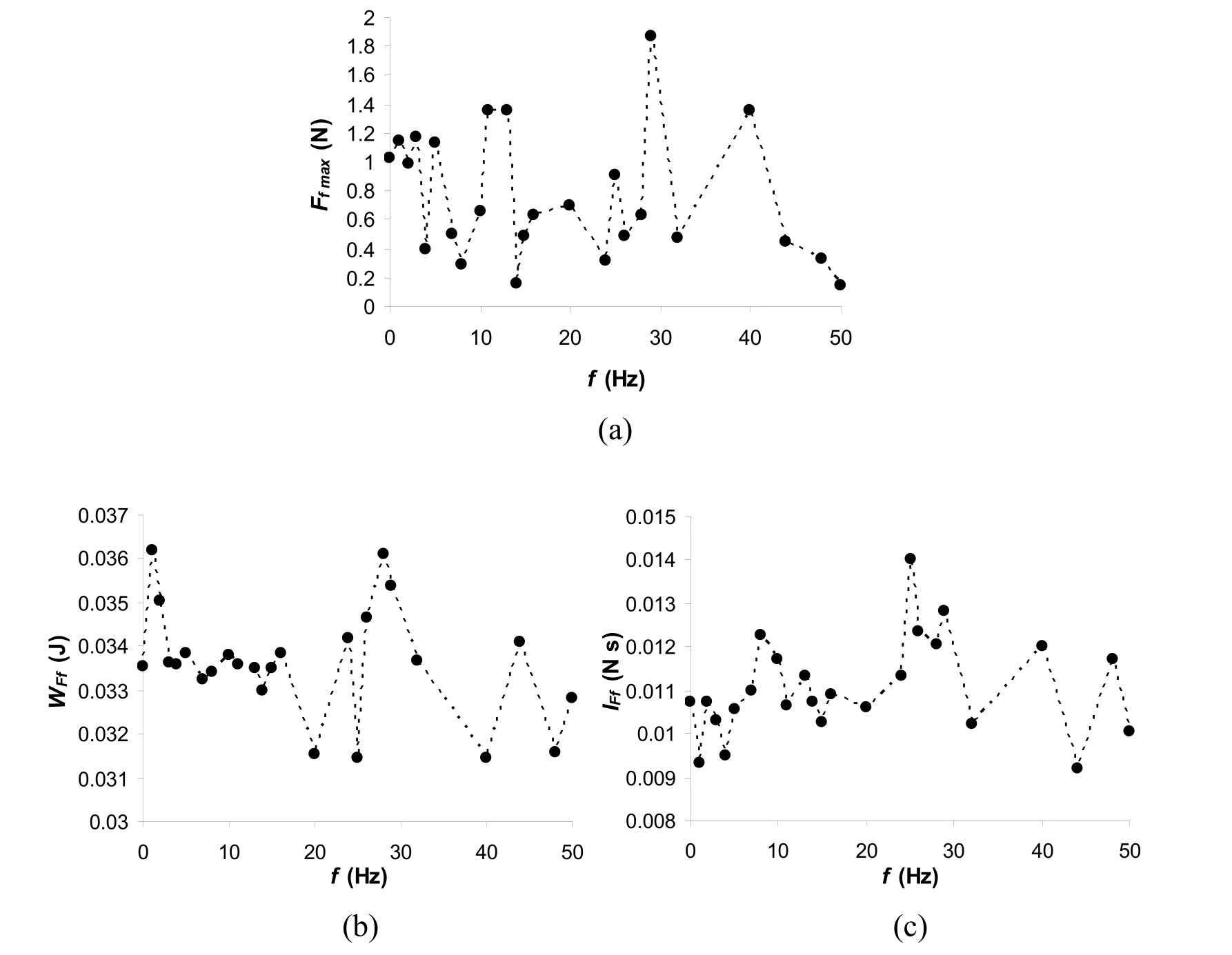
Figure 13:Force-related variables against brush frequency;cutting brush
4.3 Friction forces
Similar to the case of the F128 brush,the cutting bristle tip tends to impact the surface twice,generating high contact forces,as shown in Fig.16.Afterwards,the increasing bristle deformation maintains the contact,as well as the forces,more stable.Eventually,the tip tends to leave the surface with intermittent contact-separation events.These curves also demonstrate that the behaviour of a tilted cutting brush is very unpredictable (e.g.,curves forf=26 Hz).

Figure 14:Tip velocity squared against time,for some frequencies;cutting brush
5 Conclusions
This paper has applied a finite element brush dynamic model for studying the behaviour of tilted cutting and F128 brushes rotating at constant speed and a variable speed,in order to compare the performance of oscillatory brushes and conventional brushes.The main conclusions of the analyses are as follows.Figs.7 and 8 suggest that brush oscillations have a positive overall impact on the performance of the tilted F128 brush,for virtually all the frequencies,and several frequencies would provide a large increase in performance.Furthermore,other brushing configurations and operating parameters may provide improved performance.For instance,ωa/ωm=0.1 is rather small,and larger values may produce greater differences in brush performance for certain frequencies.Therefore,F128 brush oscillations at certain frequencies may be beneficial.This is in agreement with the experimental findings in a previous work for compacted debris [Vanegas-Useche,Abdel-Wahab and Parker (2015b)].
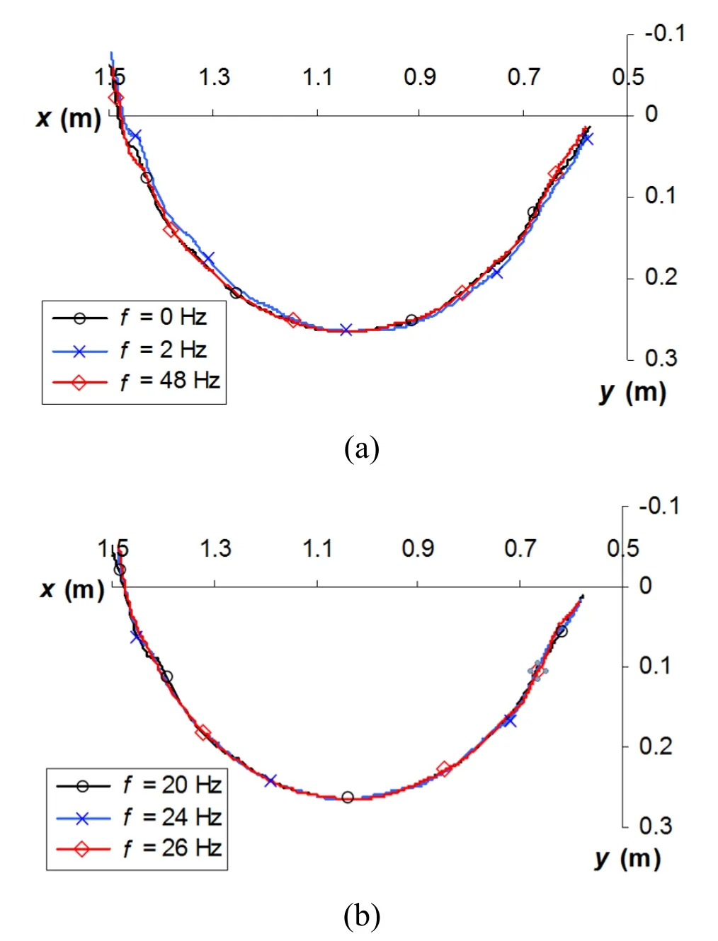
Figure 15:Path of the bristle tip,for a set of frequencies;cutting brush
As for the tilted cutting brush,it has been shown that its behaviour is more unpredictable.This is due to the stiff cutting action,as well as the dynamics generated by the heavy collisions and separations suffered by the bristles.Figs.12 and 13 suggest that some frequencies may be slightly detrimental for brush performance,whereas others may be slightly beneficial.However,an actual sweeping scenario involves debris of different types and in different conditions,which may alter dramatically brush behaviour.Taking into account the random form of the results and the uncertainties involved in the sweeping process,it could be argued that brush oscillations are not of much benefit for the cutting brush.
This work constitutes a preliminary assessment of the performance of oscillatory brushes.The model may be applied in the future to study the effects of other parameters such as oscillatory function type,b,ωa/ωm,ωm,v,γ,and Δ.Also,analyses that involve more complexities such as debris modelling may be performed.
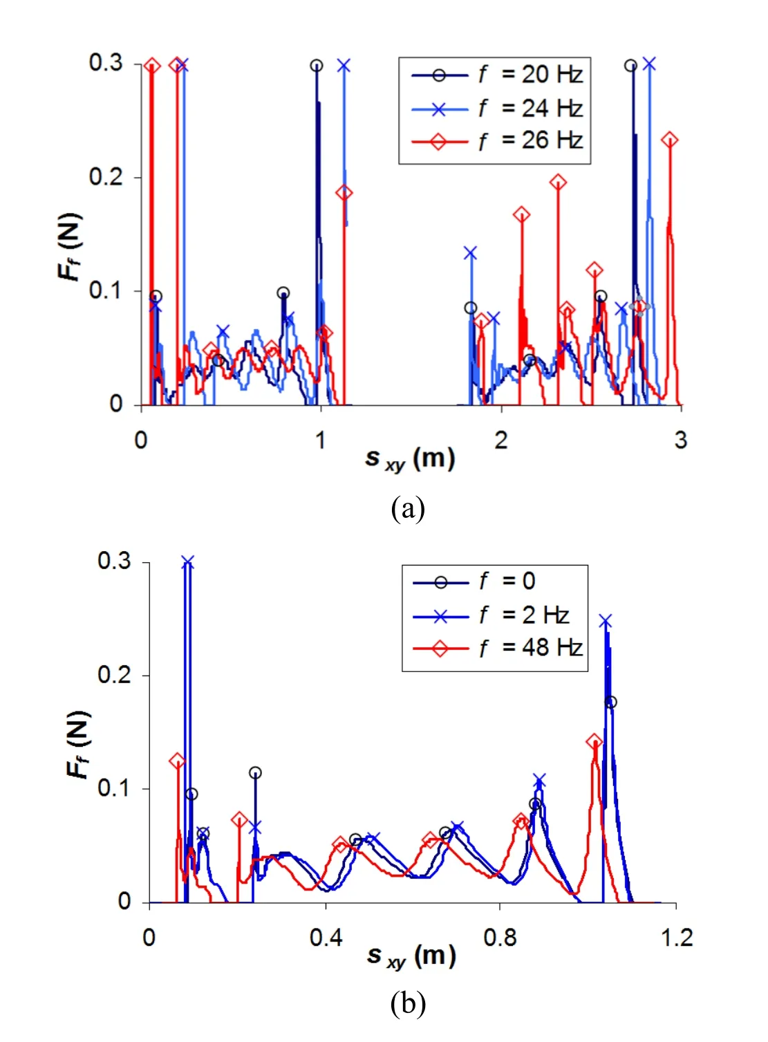
Figure 16: Friction force against tip displacement,for a set of frequencies;cutting brush
Acknowledgements:The authors acknowledge the support of the University of Surrey (UK),Ghent University (Belgium),Universidad Tecnológica de Pereira (Colombia),the Programme Alβan,European Union Programme of High Level Scholarships for Latin America,identification number (E03D04976CO).
杂志排行
Computer Modeling In Engineering&Sciences的其它文章
- Forced Vibration of the Non-Homogeneously Pre-Stressed System Consisting of the Hollow Cylinder and Surrounding Medium
- Dynamic Analyses of a Simply Supported Double-Beam System Subject to a Moving Mass with Fourier Transform Technique
- Numerical Study of Trapped Solid Particles Displacement From the Elbow of an Inclined Oil Pipeline
- Analytical and Numerical Solutions of Riesz Space Fractional Advection-Dispersion Equations with Delay
- 3-D Thermo-Stress Field in Laminated Cylindrical Shells
- Seismic Fragility Analysis of Long-Span Bridge System with Durability Degradation
