A Semi-Discretizing Method Based Efficient Model for Fluidelastic Instability Threshold Prediction of Tube Bundles
2019-11-26YuerongWangJianpingJingChangminChenandShengXiong
Yuerong Wang,Jianping Jing, ,Changmin Chen and Sheng Xiong
Abstract: Fluidelastic instability is destructive in tube bundles subjected to cross flow.Flow channel model proposed by Leaver and Weaver is well used for modeling this problem.However,as the tube motion is supposed to be harmonic,it may not simulate the general dynamic behaviors of tubes.To improve this,a model with arbitrary tube motion is proposed by Hassan and Hayder.While,due to involving in the time delay term,the stability problem cannot be solved by the eigenvalue scheme,and time domain responses of the tube have to be obtained to assess the instability threshold.To overcome this weakness,a new approach based on semi-discretizing method (SDM)is proposed in this study to make the instability threshold be predicted by eigenvalues directly.The motion equation of tube is built with considering the arbitrary tube motion and the time delay between fluid flow and tube vibration.A time delay integral term is derived and the SDM is employed to construct a transfer matrix,which transforms the infinite dimensional eigenvalue problem into a finite one.Hence the stability problem become solvable accordingly.With the proposed method,the instability threshold of a typical square tube array model is predicted,and the influences of system parameters on stability are also discussed.With comparing with prior works,it shows significant efficiency improvement in prediction of the instability threshold of tube bundles.
Keywords: Fluidelastic instability,vibration equation,time delay,semi-discretizing method,fluid-induced vibration.
1 Introduction
Tube and shell heat exchangers are widely used in conventional and nuclear industries.Tube bundles in heat exchangers are usually exposed to external flows,and the interaction between tube and fluid flow will induce tube vibration.It often leads to damage and even failures of tubes which has become a critical problem of heat exchangers [Shinde (2015)].The excitation mechanisms of Flow-Induced Vibration (FIV)can be identified as turbulence excitation,vortex shedding,fluidelastic instability and acoustic resonance broadly.As fluidelastic instability may cause severe unacceptable damage and is the most complex and difficult to predict,it has attracted more attentions than other three FIV behaviors.The feature phenomenon of fluidelastic instability is that when the flow velocity exceeds certain threshold,the amplitude of tube vibration rises sharply with a small increment of inlet flow velocity,and it may lead to the tube failure in a short time.
Due to the danger of fluidelastic instability of tube bundles,amounts of researches have been carried out to predict and prevent it,and several theoretical models for tube arrays subjected to cross flow were developed.As the fluid forces are difficult to solve theoretically,the early solution was to build a simplified model in terms of extensive experimental data.In Roberts’ experiments [Roberts Washington (1966)],transverse fluidelastic instability was observed in the in-flow direction at low flow velocities.Robert made the first attempt at analyzing the phenomenon by the Jet Switch model.Researching on a single row of tube array,Connors [Connors (1970)] proposed quasi-static model.A quantity expression between reduced flow velocity and mass-damping parameters (MDP)is given in the model.Connors did not approach the fluid forces theoretically,but measured them.Tanaka et al.[Tanaka and Takahara (1980,1981)],Chen [Chen (1983a,1983b)] provided an unsteady model,where the unsteady forces were obtained directly from experiments.Also,there were quasi-steady models developed by Blevins [Blevins (1977)] and Price et al.[Price and Paidoussis (1984,1986)],where four new constants were to be determined and couldnot account for stiffness-controlled instabilities.A semi-analytical approach to modeling fluidelastic instability was presented by Lever et al.[Lever and Weaver (1982);Lever and Weaver (1986a,1986b)] and Yetisir et al.[Yetisir and Weaver (1993a,1993b)],which was based on damping-controlled mechanism.The model was considered in the case that an elastic tube was confined in a rigid tube bundle.In the original form,the flow channel model of Lever et al.[Lever and Weaver (1982)] idealized the tube as a single degree of freedom system vibrating at its natural frequency,only in the transverse direction,and a time delay was expressed associating with the time taken for the two fluid streams on either side of the tube to readjust to the changing flow-channel configuration as a tube vibrates.Lever et al.[Lever and Weaver (1986a,1986b)] modified the flow channel to account for streamwise motion,however,the transverse and streamwise flow motions were analyzed independently of each other.Yetisir et al.[Yetisir and Weaver (1993a,1993b)] then extended the original model to account for the case of multiple flexible tubes.Since the differential motion equation was linear,the stability problem can be assessed in terms of the roots of the characteristic polynomial.Although Lever and Weaver’s model described the system behavior and fluid force theoretically,due to the assumption that tube motion is harmonic and only in the transverse direction,which is not identical to its arbitrary vibration facts,this makes the model not be suitable for nonlinear analysis.Hassan et al.[Hassan and Hayder (2008);Hassan and Weaver (2016);Hassan and Weaver (2017)] modified the semi-analytical model to account for any arbitrary motion,expanding the motion of tube to two dimensions in the plane,and developed a time domain model.Although this model may approach the arbitrary tube free motion with no limitation,it brought in a heavy burden in solving the equations by direct time integration scheme.On account of that only one inlet flow speed case corresponding to a certain MDP can be solved in once numerical computation.Moreover,time domain responses of the tube at different inlet flow speeds have to be obtained for assessing the instability via vibrational amplitudes.It will take a large amount of calculation time and hence limit its application in engineering analysis.
To avoid the time domain solution for the Hassan and Hayder’s model,the obstacle is that the time delay and unlimited vibration mode leads to an infinite-dimensional eigenvalue problem as the multiplier of characteristic polynomial has no closed form.This paper hence proposes a tube-flow coupling dynamic equation with a constant delay term and a time delay integral term based on Hassan and Hayder’s model,which supposes the tube motion is arbitrary.The SDM is then introduced to overcome the challenge via desecrating the time delay integration term.Furthermore,a transform matrix is built to make the stability problem become a finite eigenvalue one.The stability characteristics are presented by the stability map in different MDPs and effects of related parameters on stability are discussed.Finally,the results are compared with the test and theoretical one of prior researches to validate the proposed approach.
2 Elastic fluid mechanics modeling
In this study,a typical square tube array shown in Fig.1 is chosen,and the elastic fluid force is approached by reformulated flow channel model proposed by Hassan et al.[Hassan and Hayder (2008)].

Figure 1:Flow channel model
The flow passing tubes is divided into two fluid channels and wake regions as shown in Fig.1.The flexible tube (tube 5)vibrates in the X-Y plane,while other surrounding tubes are supposed to be rigid and fixed.Since fluid boundaries contact with tubes,it is influenced by motion of tubes as follows.The fluid boundary Γ1varies with the motion of the analyzed tube (tube 5).For the fluid boundary Γ2,the right end of which varies with the analyzed tube while the other end is fixed.Fluid boundaries Γ3,Γ4,Γ5andΓ6are all fixed.The curvilinear coordinate (s)is measured from the tube center along the curved path of fluid flow and s0is corresponding to the inlet position of flow channel.For simplifying the modeling,it should be noted that the fluid flow is regarded as incompressible and inviscid,as well as the fluidelastic excitation is assumed to be independent on wake phenomena.The flow is assumed to attach and separate at fixed locations.And these assumptions may not be valid for large amplitude of tube vibration.The conservation of mass equation and momentum equation obtained from the one-dimensional Reynolds equation are in following forms,respectively:

where,the fluid flow velocity U(s,t),pressure P(s,t)and the fluid channel area A(s,t)are assumed to vary with position s and time t respectively,s is the one-dimensional curvilinear coordinate along the channel.
The fluid boundaries Γ1and Γ2vary with the vibration of the tube,then the channel area A,flow velocity U and fluid pressurePfluctuate.The above three parameters can be expressed by the sum formulas of constant components and variable components,which are functions of time and position.The average channel area of the overall fluid channel A0,the flow velocity U0and the pressure P0at the inlet are assumed to be constant [Yetisir and Weaver (1993a)]:

Via substituting the Eqs.(3),(4),(5)into (1)and (2),the flow velocity and the pressure distributions along the s coordinate can be obtained by solving the equation.By integrating the pressure distribution over the fluid boundary Γ1,the force exerting on the analyzed tube (tube 5)can be obtained.Eqs.(4)and (5)are rewritten by utilizing integration by parts as

where,ℎ is the fluid resistance coefficient which is related to the arrangement and geometric parameters of tube arrays,supposed not to vary significantly with Reynolds number in the vicinity of the stability threshold for each tube bundle array.
As shown in Fig.2,the pressures in channel 1 and 2 can be calculated from the pressure distributions along the two stream channels,respectively P1(s,t)and P2(s,t).The lift and drag force on per unit length along X and Y direction are expressed respectively as

Where

saand sscorrespond to the positions of flow becoming into attachment and separation,respectively.β is the angle between the surface normal and the transverse line at s=0 of the tube.
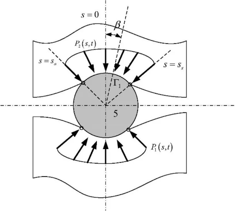
Figure 2:Pressure over the length of the channel in contact with flexible tube
Hassan and Hayder analyzed the fluidelastic instability in time domain utilizing the above model by finite element code and numerical simulation.The time domain responses of the tube have to be obtained to assess the instability via vibrational amplitudes,which inevitably involve in heavy calculation burden and judgement for instability.
To avoid assessing the stability via time-based solutions,in the following,the fluidelastic force is derived based on Hassan and Hayder’s model where SDM can be applied for,and make the instability threshold can be predicted directly in terms of eigenvalues.
For small tube responses,that is A0≫a(s,t),Eq.(6)becomes

With n=0,then

And U(s,t)is a piecewise function in the curvilinear coordinate,when s >sa,

Take the variable substitution ζ=t+2(s-sa)U0/ into Eq.(12),

Similarly,when s <sa,U(s,t)is expressed as

Combining Eqs.(2-13)and (2-14),it is obtained

In flow channel model,for any s,it gives

Combining Eqs.(16)and (8),it yields

where a1,a2are fluctuating channel area corresponding to flow channel 1 and 2.And u1,u2are fluctuating flow velocity corresponding to flow channel 1 and 2.Taking partial derivative with respect to time t on both sides of Eq.(17),it is written as follows:

For s >sa,it gives

The fluid channel area depends on the tube displacement along Y direction and the time lag.The relationship is given as

where,τ(s)is the time delay between fluid flow redistribution and the elastic tube motion.So far,there are investigations about time delay in a series of literatures,such as Lever et al.[Lever and Weaver (1982)],Price et al.[Price and Paidoussis (1984)] ,Granger [Granger and Paidoussis (1996)],and later researches [Bouzidi,Hassan,Fernandes et al.(2014);El Bouzidi and Hassan (2015);Li and Mureithi (2017)].In present work,the Lever and Weaver linear model of time delay τ(s)is adopted,which is shown as follows,

ε is the relative fluid length coefficient,which related to the phase lag of fluid flow.The phase lag is considered to be closely associated with the fluidelastic instability,which is related to the tube arrangement and pitch ratio.The value of ε is adopted as 2 in the paper.The artificial time delay function is shown in Fig.3.

Figure 3:Time delay function in the Lever and Weaver model
f(s)is the decay function,which has different forms such as linear form and exponential form.The assumed decay function f(s)on Γ2is expressed as

Eqs.(15)and (20)are substituted into Eq.(19)to produce

where

Inserting Eq.(23)into Eq.(8)and integrating it along s,the lift and drag force vectors of the tube can be obtained finally.The impacts of downstream wake and phase change due to heat transfer between tubes and fluid flow are not considered,which may lead the model too complicated to solve.The fluid forces are expressed by the state variable of displacement coordinate with the time delay term in this section,then the dynamic equation is established in the following section.
3 Dynamic equation with time delay of tube bundles
In the stability analysis of tube bundles,it can be considered that only fluidelastic instability force acts [Axisa,Antunes and Villard (1988)].The Eq.(8)indicates that the fluidelastic force in the X direction only depends on the displacement and velocity in the Y direction,which is considered as an external excitation force.And the stability in the X direction of tube bundles only depends on the system structural damping,if the damping is negative,then the system is unstable.Since it is impossible that the system structural damping is negative in practical projects,the tube response along the X direction is always stable.The stability problem of tube bundles is then simplified to one dimensional case,i.e.,only the stability in Y direction needs to be solved.As a result,for the stability problem of tube vibration,it is reasonable to assume the tube bundle as an Euler-Bernoulli beam model vibrating in the plane,whose axis is along Z direction and normal to the plane shown in Fig.1,and the simplified tube bundle control equation is written as follows:

where ρsand Asare respectively the density and lateral area of the elastic tube,η is the structural damping parameter of the system,E and I are Young’s modulus of the beam and the cross-sectional moment of inertia,FL(z,t)is fluidelastic force in transverse direction.By mode superposition method,extracting precedingNmodes,there is y(t)=It is demonstrated both by theory and experiments that the critical velocity corresponding to the first order mode is the lowest.Hence intercept the first order mode by Galerkin method and integrate with φ1(z),then the tube partial differential equation is converted into the ordinary differential equation:

where fL(t)is defined as follows,

Rearranging Eqs.(23),(25)and (26),the following simplified form is obtained:

Making a variable substitution,we obtain

where,

Through the above model simplification,the tube dynamic equation is derived,whose right side is composed by a constant delay term and a time delay integral term and the stability problem is transformed to be solvable,where SDM could be applied.The equation is established on the assumption that the tube vibrates in small amplitude in the plane.The new dynamics Eq.(28)takes the first-order mode coordinate as state variable.The details of solving method and process for the proposed model by the SDM are presented in the next session.
4 Solution of fluidelastic dynamics equation
Autonomous ordinary differential equations (ODEs)have the general form

The stability properties are determined by the roots of the characteristic polynomial:if and only if all the characteristic roots have negative real parts,the system is asymptotically stable.Opposite to the characteristic polynomial of autonomous ODEs,for the linear autonomous DDEs in the following form,the characteristic function has infinite number of zeros.

In the DDEs,the sufficient and necessary condition for asymptotic stability is that all the infinite number of characteristic roots have negative real parts.For practical calculations,only approximations can be applied.Stability investigations are often carried out by numerical simulations and the SDM is composed and applied for determining stability criteria for second-order DDEs by Insperger et al.[Insperger and Stépán (2011)].
For the DDE (28),the challenge of fluidelastic instability analysis is that the time delay and unlimited vibration mode lead to an infinite-dimensional eigenvalue problem as the fundamental matrix of characteristic polynomial has no closed form,and it cannot be solved by traditional method.In this section,with the application of SDM,the infinite-dimensional eigenvalue problem is transformed into an approximate finite-dimensional one,and the fluidelastic instability threshold can be predicted by the eigenvalues.SDM has been widely used in solid finite element analysis and computational fluid dynamics,the basic idea of which is to discretize the partial differential equation only along the spatial coordinate without the change of the time coordinate [Insperger and Stépán (2002)].In this work,the SDM is introduced to construct a transfer matrix,then the stability of the tube-flow coupled control equation with time delay can be determined by its eigenvalues.An overview of stability map will be provided indicating the correlation between the fluidelastic instability threshold and system parameters,which is efficient for predicting of fluidelastic instability.The stability of the dynamic equation is solved by employing SDM as follows.
The length of time axis is divided into a series of time intervals,and the period T is expressed as T=kΔt,k ∈Z.The relationship between k and m is as


where,in this work,

W(ϑ)is an impulse weighting distribution matrix and it is integrable,which satisfies the following equation:

At the interval [ti,ti+1],W(ϑ)=Wi(ϑ).The continuous distribution matrix(ϑ)can be expressed as a sum of a series of impulse function [Insperger and Stépán (2002)]:

Meanwhile,at the interval [ti,ti+1],(ϑ)can also be expressed as a sum of a series of time-dependent distribution [Insperger and Stépán (2002)],

With the above approximations,the following approximate form is obtained [Insperger and Stépán (2002)],

where

Substitution of Eq.(36)into Eq.(32)yield

Where

Assuming A is reversible for all i,the solution of Eq.(38)is [Insperger and Stépán (2011)],

where the constant vector Kidepends on the initial value of the state variable x,namely

If A is irreversible,there is also a corresponding expression,and SDM is still applicable.In our work,it will not be discussed in detail.
Eq.(41)is substituted into Eq.(40)to get [Insperger and Stépán (2011)],

where the coefficient matrices are

Eq.(42)gives the linear correlation of the system state variables xi+1at the time t =ti+1and xiat the time t =ti.

By the Eq.(42)and Eq.(45),we have

where the coefficient matrix

Utilizing Eq.(46)we obtain

Then the transfer matrix over the period T is given in the form

By the construction of the transfer matrix φ,the stability of Eq.(42)then can be assessed by judging whether its eigenvalues are all in the unit circle.If all the eigenvalues are in the unit circle [Lakshmikantham and Trigiante (2002)] ,then the solution of the Eq.(32)is stable.Let λmaxbe the maximum modulus among all eigenvalues for φ.If λmax>1,then the system is unstable;if λmax<1,then the system is asymptotically stable;else when λmax=1,the system is marginally stable.
5 Results and discussion
In the view of the damping mechanism for fluidelastic instability of the tube bundle,the system instability occurs when the energy the tube obtained from the flow field is more than that it dissipated.The system damping and flow velocity are important factors affecting system stability.Therefore,the mass-damping parameter (MDP)is introduced as an important factor for fluidelastic instability.The expression of the MDP is

where m and δ are respectively the tube mass in per unit length and logarithmic decrement of structural damping,D is the tube diameter.
The relevant geometrical parameters and material properties in computation are listed in Tab.1.Fig.4 shows influences of MDP and reduced flow velocity Ur(Ur=U0fn/ D)on the modulus of the transfer matrix eigenvalues.The stability surface is constructed by computing 50 groups of MDPs respectively in 200 flow velocities and it divides the space into stable and unstable regions.To observe the region where λmax>1 in (a)visually,let λmax=1 as in (b),then the discrete points corresponding to λmax=1 compose a curve,namely,the system stability curve.Extracting mass damping parameters and reduced flow velocities corresponding to the curve,a fitted stability curve in the plane is figured out,shaped like a parabola as in Fig.5.In Fig.5,the system stability curve divides the plane into two parts,the stable region which is shaded and unstable region which is white.Then for analyzing the relationship between MDP and Urquantitatively,the curve is fitted according to Connors’ model since there are several empirical design guidelines based on the Connors’ equation are developed [Hassan and Hossen (2010)].In the engineering,the critical pitch flow velocity Ucis always expressed as follows,

where ρ is the fluid density,K and γ are empirical constants.fnis the structural natural frequency of tube in air circumstance and the simulations and referred experiment results in the paper are acquired in air flow.Over past five decades,a lot of experimental investigations are carried out in order to modify the constants to be suitable for different tube arrays.In this work,Connors’ model is chosen as a reference to fit the stability curve and the pitch-diameter ratio chosen is 1.5.
As shown in Fig.5,the corresponding critical reduced flow velocities in 50 cases of MDP are computed.And several typical MDP and critical reduced flow velocities are listed in Tab.2.Furthermore,the curve is fitted by these points in the form of Eq.(51)and values of K and γ are obtained accordingly,which are 5.428 and 0.434 respectively.The fitted curve indicates that the critical flow velocity increases with MDP.In the lower MDP condition,it increases sharply and with the MDP increasing,the slope of the critical velocity growth becomes gentle continuously.

Table 1:Material properties and geometrical parameters
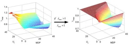
Figure 4:Fluid elastic stable area of tube bundles

Figure 5:Curve fitting of mass damping parameter vs reduced flow velocity

Table 2:Typical MDP and reduced critical flow velocity values
The Reynolds numbers depending on the mean gap flow velocity over the range of Re= 273 to Re= 1092 are listed in Tab.3.The dimensionless flow velocity (Ur∗=U/fD)and pressure distributions along the flow channel in a certain MDP under several flow velocities are also showed respectively in Fig.6 and Fig.7.As mentioned in the flow channel model,the locations along the fluid channel are described by one dimensional curvilinear coordinate s,the velocity U(s,t)and pressure P(s,t)are computed along the coordinate s,the distributions of which in transverse direction of flow channels are not presented.The location index ( s∗=s/D)is introduced as shown in Fig.6 and Fig.7,which is the coordinatesscaled with the tube diameter.It respectively takes values of -1.5,0,and 1.5 along the channel centerline at locations responding to the centers of tubes.It is observed that the velocity fluctuates along the coordinate s,and it holds a peak level in the vicinity of the tube.And there is a general downward trend with the pressure distribution as it fluctuates along the coordinate s in a certain Reynolds number.It shows that for low Reynolds numbers in scope of this paper where turbulence could be negligible,the velocity and pressure distribution respectively present similar trends along the channel coordinate while mean values rise with the increase of Reynolds number.

Table 3:Reduced flow velocities and Reynolds numbers
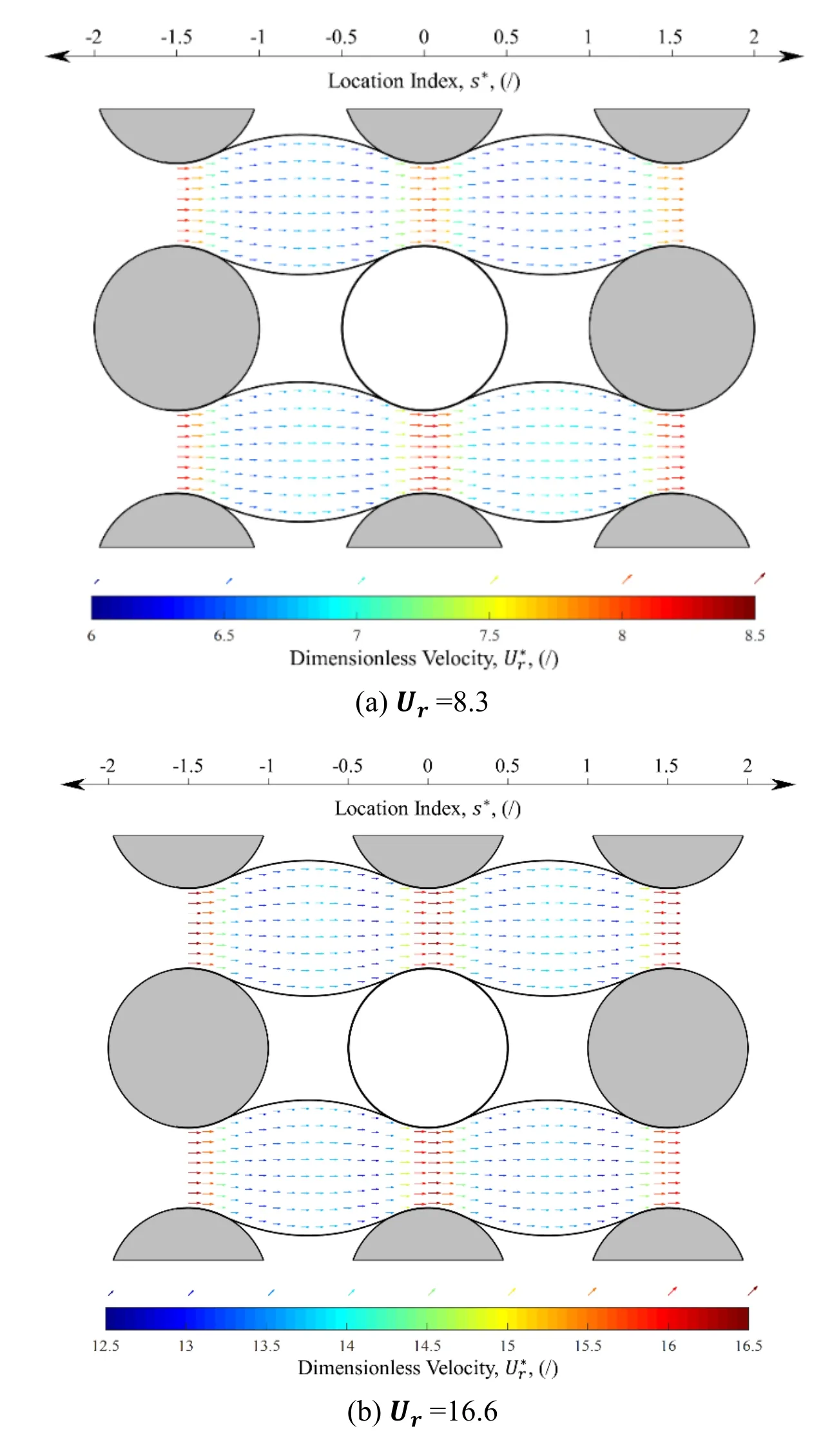

Figure 6:The velocity distribution along the flow channel

Figure 7:The pressure distribution along the flow channel
The computation result of our model is then compared with former reported results in Fig.8,which presents together the computation result in this work and the experimental data in previous researches as well as the simulation result of Hassan and Hayder’s model.The comparison indicates that the results obtained by this proposed method are consistent with the reported experimental and simulation results,and the curve shows better consistency and smoothness than the one by Hassan and Hayder.For the reason that the latter is fitted by limited number of points due to the large amount of calculation time cost,it is difficult to present a smooth curve.Moreover,in Hassan and Hayder’s model,the critical flow velocities are separately obtained by vibrational amplitudes of the time domain response in certain MDP condition.While the proposed new method could easily solve amounts of MDP conditions in numbers of flow velocities in one computation.In this study,50 cases of MDP respectively in 200 flow velocities are used to satisfy efficiency demand.However,discrepancies exist between the simulation curves and the scattered experimental data in Fig.8.This indicates that due to the complexity of fluid-structural interaction,it is difficult to model and simulate the fluidelastic mechanism accurately by the models with much hypothesis and simplifications.Although the original flow channel model is progressive,it has deficiencies as a result of a series of assumptions and approximated parameters.The channel flow is assumed to be incompressible and inviscid,as well as wake phenomenon is ignored.Moreover,some artificial parameters such as the time lag,the position of separation and attachment points may also involve in errors.The fluid mechanics model is hence expected to be further improved in the future,which may approach the fluidelastic behavior more accurately.

Figure 8:Comparison of mass damping parameter vs reduced critical velocity among results of new method and other published data for pitch-diameter ratio of 1.5
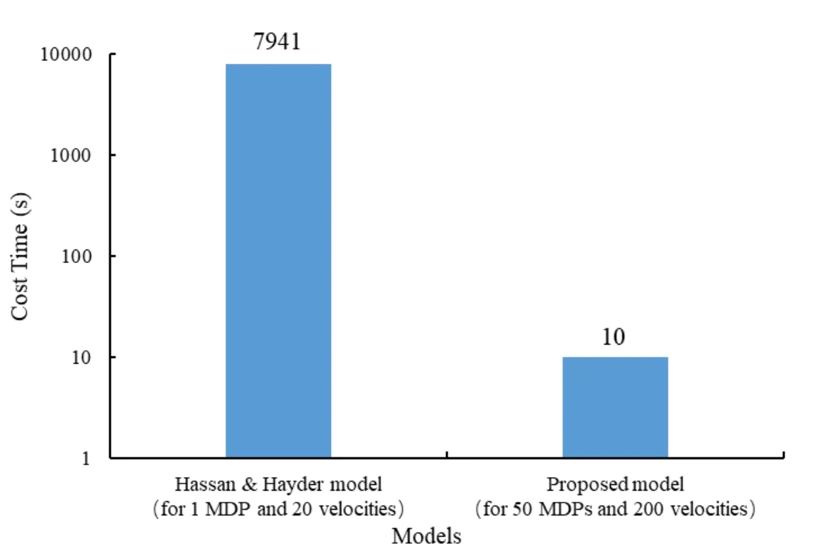
Figure 9:Comparison of time cost by proposed model and Hassan & Hayder model
The computation of proposed model for 50 MDPs respectively in 200 flow velocities spends 10 s in total,while it costs 2.2 hours for only one certain MDP simulation solving 20 flow velocities using Hassan and Hayder’s model.The comparison is shown in Fig.9.It demonstrates that the computation time is significantly reduced and efficiency is improved dramatically.
In the Connors’ Eq.(51),the tube instability only depends on MDP and the reduced flow velocity.The coupling effects between tube and fluid flow is not reflected.Now the impacts of fluid parameters will be discussed by the proposed method.
In the view of damping-controlled mechanism theory,the tube-flow coupling system includes both structural damping and fluid drag forces.The drag force coefficient ℎ related to the resistance influence during the process the fluid flow passes through the tube bundles,which can be calculated by solving the average pressure drop based on energy principle.In Fig.10,the tube stability curve at different ℎ shows that,the greater stability region area appears with the value of ℎ increasing in Ucr-MDP diagram.The reason is that higher ℎ value means more energy is dissipated for the coupling system,consequently the system has better stability in terms of energy conservation law.

Figure 10:Effect of fluid resistance parameter on the stability of the tube response
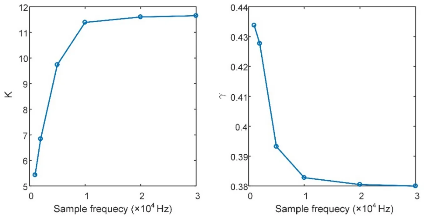
Figure 11:Effect of sample frequency on the parameter of fitting curve
On the condition that the flow velocity is constant,in the SDM,the dimension of the transfer matrix is determined by the sample frequency,which also has an influence on the computation accuracy and efficiency of stability maps.The Fig.11 shows the effect of sample frequency on the fitting curve coefficient K and γ.It indicates that the parameters change significantly with the sample frequency when it is below 10 kHz.And when the sample frequency exceeds 10 kHz,the changes of parameters are small and negligible.Considering that the calculation amount also increases with sample frequency,10 kHz is hence chosen as the sample frequency for the stability computation.
5 Summary
The proposed model is developed based on flow channel model and the tube motion is set to be arbitrary without limitation.The time delay between flow redistribution and tube vibration is also considered.The SDM is introduced in this study to analyze the stability problem of the dynamic equation with a constant delay term and a time delay integral term.The stability map of tube vibration is figured out visually based on eigenvalues of the built transfer matrix by SDM.Account for the unlimited tube motion and predicting the instability threshold directly via eigenvalues based on SDM,this proposed method presents definite improvement in computation efficiency with comparing to Hassan and Hayder’s model.
Numerical investigations of a single flexible tube within a rigid array subjected to crossflow are carried out for a typical square array.Effects of tube structural parameters and fluid related parameters may affect the stability are discussed.The stability depends on MDP mainly,which is determined by tube structural parameters.The stability is also influenced by fluid related parameters.When the fluid passes through tube bundles,greater fluid resistance may lead to more stable tube vibration than lower one.As the flow channel model is based on a series of assumptions and empirical parameters,in the future,a more elaborate fluid mechanics model is expected to be developed,which may predict the instability threshold with higher accuracy.
Acknowledgement:The support from the National Natural Science Foundation of China (No.11672179)is greatly acknowledged.
Appendix A.Nomenclature
X and Y directions the tube moves along
s one dimensional curvilinear coordinate
s0,sa,ssposition of flow channel inlet,attachment point,separation point
Γfluid boundary
A,A0,aflow channel area:along the fluid channel,average state,perturbation
U,U0,uflow velocity:along the fluid channel,at the inlet,perturbation
P,P0,pfluid pressure:along the fluid channel,at the inlet,perturbation
FL(t),FD(t)lift and drag force on the moving tube
ℎ fluid resistance coefficient
τ(s)time delay function
εrelative fluid length coefficient
ρs,ρ the elastic tube density,fluid density
Aslateral area of the elastic tube
ηstructural damping parameter of the system
E Young's modulus
I cross-sectional moment of inertia
W(ϑ)Impulse weighting matrix
Δt time interval
Δω frequency interval
B transfer matrix
m tube bundle mass per unit length
δlogarithmic decrement
D diameter of the tube
[C] tube damping matrix
φtransfer matrix of a cycle
Ur,Ur∗,reduced flow velocity:at the inlet,along the fluid channel
Uc,Ucrcritical flow velocity,reduced critical flow velocity
λmaxthe maximum modulus of the eigenvalues of the φ
fnstructural natural frequency
K and γ empirical constant coefficients
杂志排行
Computer Modeling In Engineering&Sciences的其它文章
- Forced Vibration of the Non-Homogeneously Pre-Stressed System Consisting of the Hollow Cylinder and Surrounding Medium
- Dynamic Analyses of a Simply Supported Double-Beam System Subject to a Moving Mass with Fourier Transform Technique
- Numerical Study of Trapped Solid Particles Displacement From the Elbow of an Inclined Oil Pipeline
- Analytical and Numerical Solutions of Riesz Space Fractional Advection-Dispersion Equations with Delay
- 3-D Thermo-Stress Field in Laminated Cylindrical Shells
- Seismic Fragility Analysis of Long-Span Bridge System with Durability Degradation
