Experimental study on the temperature evolution in the railway brake disc
2019-11-04AleksnderYevtushenkoMichKuciejPiotrWsilewski
Aleksnder Yevtushenko, Michł Kuciej, Piotr Wsilewski
a Faculty of Mechanical Engineering, Bialystok University of Technology (BUT), 45C Wiejska Street, Bialystok 15-351, Poland
b Frimatrail Frenoplast S.A, Watykańska 15, 05-200 Majdan, Poland
Keywords:Railway disc brake Heat partition Thermal conductivity Full-scale dynamometer test
A B S T R A C T Increasing operating speed of modern passenger railway vehicles leads to higher thermal load on the braking system. Organic composite brake pads are poor thermal conductors, hence frictional heat is absorbed mainly by the disc. In this study three brake pad types were tested on the dynamometer. Metallic fibres, steel and copper, were introduced to the formulation of two materials. The third was a non-metallic material - a reference case. Dynamometer test comprised emergency brake applications to determine the frictional characteristics of the materials and constant-power drag braking to analyse the effect of metal fibres on temperature evolution,measured by six thermocouples embedded in the brake disc. Mean friction coefficient is analysed and discussed. It is concluded that conductive fibre in the friction material formulation may influence its tribological characteristics. Despite high thermal conductivity, metal fibres in the concentration tested in this study, did not reduce temperature of the brake disc.
Friction brake in railway vehicles is applied to decelerate,maintain constant velocity while negotiating the descent and to hold the vehicle stationary. As the requirements concerning braking performance grew and the maximum velocity of railway passenger vehicles increased, tread brakes were gradually superseded in passenger rolling stock by disc brakes [1-3]. In railway disc brakes friction force is generated at the interface of the stator (brake pads) and rotor (brake disc) - a friction pair. When brake is applied, kinetic energy is dissipated into heat, leading to increase in the temperature of the friction pair, which is worn in the process.
In the course of the design process of railway brake system,thermal load, which the friction pair will be exposed to, is the key issue. Depending on the operating temperature, different materials may be selected for manufacturing of the friction elements(e.g. cast iron or steel brake disc, organic or sintered brake pads).The choice of the friction pair is often verified by means of fullscale dynamometer tests, which allow to simulate the actual operating conditions of the railway vehicle. The test results are analysed to define frictional characteristics of the materials, e.g. the effect of the temperature and operating conditions on the coefficient of friction and wear. An insightful summary of the influence of temperature, contact pressure and initial braking velocity on tribological characteristics of friction materials used in brakes is presented in Ref. [4]. Another important factor subject to assessment is whether, under given conditions, thermal degradation or destruction occurred.
In the course of the dynamometer test, temperature may be measured with: thermocouples (e.g. K-type) installed below the friction surface of the brake disc [5, 6] or brake pads [7] as well as sliding thermocouples [8, 9]. Studying the phenomena related to non-uniform or localised heat flow requires thermographic methods [10, 11].
Relatively high cost of the dynamometer testing justifies application of simulation methods to estimate operating temperature of the friction pair under given conditions. A review of the studies concerning numerical models used to determine temperature fields in railway brakes was presented in Ref. [12].
When brakes are applied, in particular during drag brake application, emergency brake application or sequence of brake applications without cooling period, the brake disc is exposed to extensive thermal load. Day et al. defined two general types of thermal effects: i) bulk effects, such as coning and ii) local effects, e.g. cracks [13]. Thermal and mechanical stress as well as locally overheated areas, which are induced by frictional heating, lead to structural change of the brake disc material, cracking and other damage which in turn have negative effect on its service life.
Taking into account the requirements concerning durability,reliability and, above all, safety of railway vehicles, reducing thermal load to which the brake disc will be subject to in operation is a worthwhile task. Considering the fact that organic composite friction materials are characterised in general by low thermal conductivity, increase in its value should have a positive effect on brake disc lifespan. To achieve this metallic fibres may be introduced in the formulation [14].
The purpose of this study was to analyse the effect of the metallic reinforcing fibre type on frictional properties of railway organic composite brake pads as well as its influence on the temperature fields in the course of brake application.
The prototype brake pads were manufactured from friction mixtures by moulding to comply with standard UIC200 shape of railway brake pads [15]. Moulded parts underwent thermal treatment to ensure curing of the thermosetting phenolic resin. Finally, the brake pads were ground to the thickness of 35 mm.The basic formulation contained rubber, phenolic resin, mineral fibre, graphite, antimony trisulfide (Sb2S3), calcite and curing agents.
To study the effect of the metallic fibre on the properties of the composite, three mixtures (denoted Material I, Material II and Material III) were manufactured by adding specified amount of filler to 70 kg of the basic formulation (Table 1). The amounts of filler added were defined to ensure that their volume is equal (considering specific density). To establish a reference case, non-metallic material (Material I) was manufactured,where additional amount of calcite instead of metallic fibre was introduced.
The prototype brake pads were tested on a full-scale dynamometer at the Railway Institute (Instytut Kolejnictwa) in Warsaw, Poland. Cast iron brake disc with nominal outer diameter of 640 mm was used. One set subject to testing comprised two "left-hand" brake pads and two "right-hand" brake pads. The test programme included 20 stop brakings in dry conditions -the parameters are presented in Table 2. Braked mass per disc was 5000 kg and the initial temperature for each brake application was between 50°C and 60°C, with the exception of the 1st and 11th brake application, where the initial temperature was between 20°C and 30°C.
In addition to stop brakings, constant power (20 kW) drag brake application was performed. The velocity of 80 km/h was maintained for 1800 s. The remaining test conditions, such as ventilation and cooling of the friction pair between brake applications were compliant with the requirements prescribed in Ref.[15]. The braking torque was measured in the course of brake applications and instantaneous coefficient of friction was calculated (the tangential force divided by the contact force). Calculation of the mean coefficient of friction was performed as defined in Ref. [15]. Six K-type thermocouples were used to measure the temperature. Thermocouples were installed symmetrically on both friction rings 1 mm below the contact surface: two at the equivalent braking radius and the remaining displaced 120°: two 40 mm outside and two 40 mm inside the equivalent braking radius.
The test results presented on Figs. 1 and 2 are values of average coefficient of friction calculated as an arithmetic mean from two measurements (e.g. brake applications No. 1 and 11, No. 2 and 12, etc.).
Analysis of the results shows that the coefficient of friction of each tested composite material is dependent on initial velocity and contact force. At a contact force of 20 kN, the highest coefficient of friction was exhibited by Material III and the lowest by Material I, with the exception of the average coefficient of friction at an initial velocity of 80 km/h, which was approximatelyequal for Material I and II (0.213 and 0.212 respectively, Fig. 1).The difference between maximum and minimum value of the coefficient of friction was the highest for Material I (0.213 at 80 km/h and 0.140 at 160 km/h) and the lowest for Material II(0.212 at 80 km/h and 0.173 at 200 km/h).
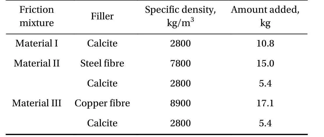
Table 1 Design of the formulations tested
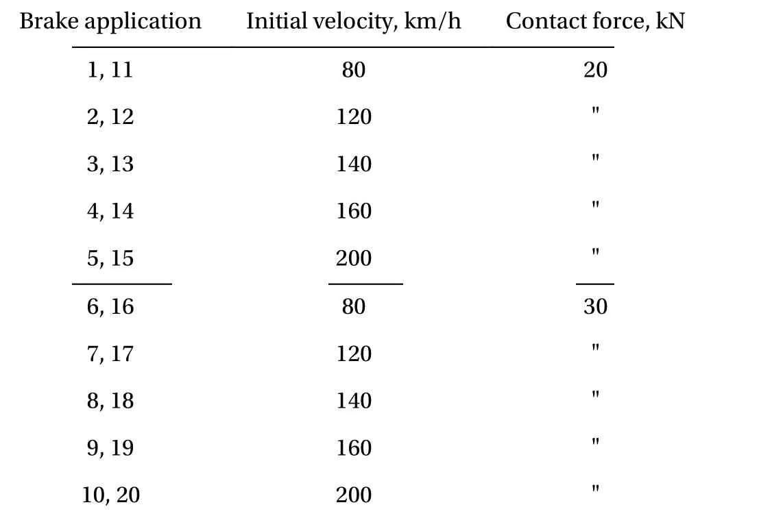
Table 2 Full-scale dynamometer test programme
In the case of Material I and II, the coefficient of friction at a contact force of 30 kN was higher as compared to values measured at 20 kN (with the exception of the results for Material I at an initial velocity of 80 km/h) - see Fig. 2. The results for Material III show decrease in the friction level in the whole range of the tested initial velocities, although it is less significant at 160 km/h and 200 km/h. In the range of the initial velocities of 80 km/h to 140 km/h the highest coefficient of friction was exhibited by Material II. At 160 km/h and 200 km/h the maximum values of the coefficient of friction were measured for Material III. At a contact force of 30 kN the coefficient of friction of Material I and Material III is less dependent on the initial velocity as compared to the results at 20 kN. In the case of Material II the average coefficient of friction at an initial velocity of 200 km/h is distinctly lower than the value determined at 120 km/h. Futhermore, the dispersion of the test results for Material II and Material III is significantly lower at 30 kN contact force in comparison to the dispersion at 20 kN. For Material I the difference is not that pronounced. The diverse behaviour of the tested composite materials may be explained by the effect which the contact force has on the actual contact area. It is also influenced by mechanical properties of the friction material such as compressibility, which in turn are dependent on the formulation, in particular on the reinforcing fibre used.
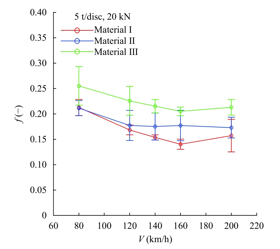
Fig. 1. Average coefficient of friction at 20 kN
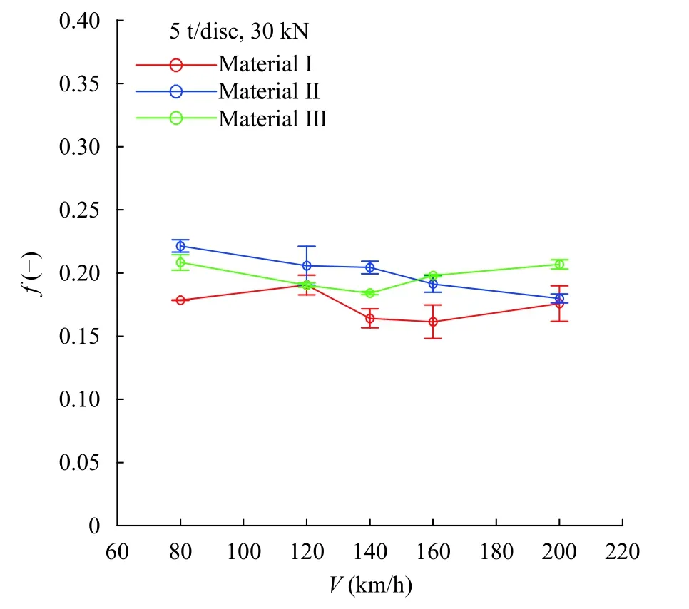
Fig. 2. Average coefficient of friction at 30 kN
To find the root cause of the differences in frictional characteristics of the studied composite materials, it is necessary to consider micro-contact on the friction interface as well as wear process. Higher friction coefficient of the composite materials with metallic fibres in their formulation (Material II and Material III), as compared to the non-metallic material (Material I) may be explained by metal-metal contact which is characterised by high adhesion [16]. Furthermore, metallic fibres conduct frictional heat away from the interface, thus reducing the temperature on the contact surface and inhibiting thermal degradation of the phenolic resin [17]. Analyses of worn surfaces and wear debris would most probably provide additional insight into this problem since the debris and friction film generated in the course of braking process have significant effect on the coefficient of friction [4], this, however, was not part of the current study.
To study the effect of the friction material on the disc temperature evolution, drag brake application was introduced in the test programme. Braking torque was measured and used to control the contact force (Fig. 3). This way braking power and nominal heat flux were maintained constant and independent of changes in the coefficient of friction.
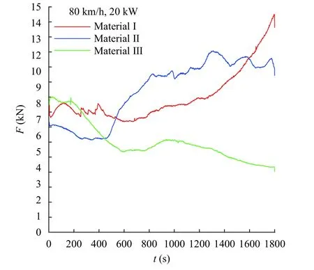
Fig. 3. Change in the contact force in the course of drag brake application
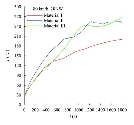
Fig. 4. Disc temperature evolution in the course of drag brake application
Temperature was measured by six K-type thermocouples with a frequency of 10 Hz. The arithmetic mean of the measured values for each of the materials tested is drawn in Fig. 4. The lowest temperature (200.5°C) at the end of brake application (t=1800 s) was reached during the test of Material I. Disc temperature was significantly higher when materials which contained metal fibres in their formulation were used - the values at t=1800 s were 250.4°C and 268.7°C for Material II and Material III respectively. Temperature evolution was quite similar during first 500 s for Material I and Material III. After that the temperature increase rate determined for Material I drops, while the temperature of the disc braked by pads from Material III still rises sharply reaching at t ≈800 s level comparable with that of temperature values for Material II. In the course of the first 800 s, temperature of the disc tested with Material II was the highest. Temperature evolution for the disc equipped with brake pads manufactured from Material I was the most stable, while measurements for Material II and III exhibited some fluctuations after the mean temperature exceeded 200°C (Material II) and 240°C (Material III).
The reinforcing fibres have significant influence on the frictional characteristics of the railway disc brake pads. The addition of metal fibres to the formulation of the composite organic friction material - namely steel and copper - in the concentration tested in this study, did not reduce the temperature of the brake disc despite their being good thermal conductors as compared to calcite. The temperature reached by the brake disc at the end of constant-power drag brake application was the highest for non-metallic material. This result requires further investigation. One of possible reasons is that the content of the metal fibres was not sufficient to form thermally conductive paths. It is planned to manufacture and test friction materials with higher concentration of metal fibres.
Thermal diffusivity depends on thermal conductivity and specific heat capacity - measurements of these thermophysical properties may provide valuable insight into heat transfer in the course of brake application.
Acknowledgements
This article was supported by the National Science Centre of Poland (Research project No. 2017/27/B/ST8/01249).
杂志排行
Theoretical & Applied Mechanics Letters的其它文章
- Editorial: Thermal Stresses
- Stresses of orthotropic laminated beams subjected to high temperature and mechanical load
- Thermoelastic stability of closed cylindrical shell in supersonic gas flow
- Transient thermal response of functionally graded piezoelectric laminates with an infinite row of parallel cracks normal to the bimaterial interface
- Stochastic transient analysis of thermal stresses in solids by explicit timedomain method
- 3D thermally induced analysis of annular plates of functionally graded materials
