Area-oriented coordinated trajectory planning of dual-arm space robot for capturing a tumbling target
2019-10-26WenfuXULeiYANZhonghuHUBinLIANG
Wenfu XU, Lei YAN, Zhonghu HU, Bin LIANG
a School of Mechanical Engineering and Automation, Harbin Institute of Technology, Shenzhen 518055, China
b State Key Laboratory of Robotics and System, Harbin Institute of Technology, Harbin 150001, China
c Department of Automation, Tsinghua University, Beijing 100084, China
KEYWORDS Area-oriented capture;Dual-arm coordination;Space debris removal;Space robot;Tumbling target capturing
Abstract The growing amount of space debris poses a threat to operational spacecraft and the long-term sustainability of activities in outer space.According to the orbital mechanics, an uncontrolled space object will be tumbling, bringing great challenge to capture and remove it. In this paper, a dual-arm coordinated ‘‘Area-Oriented Capture” (AOC) method is proposed to capture a non-cooperative tumbling target. Firstly, the motion equation of the tumbling target is established, based on which, the dynamic properties are analyzed. Then, the ‘‘Area-Oriented Capture”concept is presented to deal with the problem of large pose (position and attitude) deviation and tumbling motion. An area rather than fixed points/devices is taken as the object to be tracked and captured.As long as the manipulators'end-effectors move to a specified range of the objective areas(not fixed points on the target,but areas),the target satellite will be hugged by the two arms.At last,the proposed method and the traditional method(i.e.fixed-point oriented capture method)are compared and analyzed through simulation. The results show that the proposed method has larger pose tolerance and takes shorter time for capturing a tumbling target.
1. Introduction
The growing amount of space debris poses a threat to operational spacecraft and the long-term sustainability of activities in outer space.1,2It is very urgent to remove them and protect the orbital environment. A space robotic system is one of the most effective way to deal with these uncontrolled space objects.3Flores-Abad et al.overviewed the main achievements in space robotic technologies.4Compared with a single-arm space robot, a multi-arm robotic system has much more dexterity and flexibility, and is capable of performing more complex tasks.5,6
However, the space debris is non-cooperative and uncontrolled. It is generally in the state of tumbling, bringing great challenge to capture and remove it. Shan et al. summarized and compared the main techniques, and classed the contact capture methods into two types.7One is the stiff connection capture using robotic arms or tentacles;8-10the other is flexible connection capture using tethered flying net or flying gripper.11The latter allows the capture from long distance between the target and the chaser spacecraft. Huang et al. studied the dynamics modeling and coordinated control of tethered space robots for on orbit servicing tasks.12,13They proposed very effective methods to deal with the dynamics problems under some basic assumptions. However, for further maintenance,reuse or other operations of the captured target, the stiff connection capture using robotic arms is an important measure and mainly considered in this paper.
The scholars proposed some useful methods for autonomous target capturing using space robots. Xu et al. presented an autonomous target capturing method of free-floating space robot,14and the target berthing and base reorientation methods after capturing.15In order to minimize the attitude deviation of the base, Yoshida et al. applied the bias momentum method for the manipulator to approach the target.16Then,the impedance control and the distribution momentum methods were respectively used for contact and post-capture stages.Cheng et al. proposed the ‘‘dynamic grasping area” for space robots capturing floating target, the impact force and control torque are both reduced.17For a non-cooperative spacecraft,Nagamatsu et al. estimated the target motion using the Kalman filter,and controlled the manipulator to complete the capture of a spinning target based on a simplified dynamics model.18Lampariello transformed the capturing problem into a point-to-point trajectory planning by analyzing the capture point motion of the tumbling target, and adopted the nonlinear optimization method to solve this problem.19This method consumes a lot of time and it will not be applicable due to the error of the predicted target trajectory, or the change of the target motion state. Aghili presented a combined prediction and motion planning scheme to capture a tumbling object with unknown dynamics using a Kalman filter to estimate the states and dynamics parameters from noisy measurements of a vision system.20Flores-Abad et al. proposed optimal control strategies to capture a tumbling object for different initial conditions and stages.21The optimal time and target motion are first determined, and the manipulator is controlled to reach the object at the predicted time along the optimal trajectory.
However, the above works mostly focus on capturing a cooperative target, or simple spinning target (only pure spinning motion is considered; the nutation is generally ignored).In fact, an uncontrolled target in space will be tumbling with both spinning motion and nutation. Few works considered such a real situation.The traditional methods took some fixed points or structures on the target as the objects to be measured and grasped. For an actual tumbling target, the movement of such objects has the following characteristics: (A) the movement range will be large and beyond the workspace of the manipulator; (B) the movement speed will be high, and the available capture time is short. These characteristics brings increasingly large challenges for capturing a tumbling target.The existing methods are still not satisfactory. In this paper,we propose a coordinated ‘‘Area Oriented Capture” (AOC)method for a dual-arm space robot to capture a noncooperative tumbling target on orbit. The areas rather than fixed points/structures are considered as the objects to be tracked and captured. Compared with the traditional method(i.e. fixed-point oriented capture method), the manipulator in AOC method will move in smaller range. It has larger tolerance for relative pose deviation and longer available time for capturing.
The remainder of this paper is organized as follows. In Section 2, the dynamics model of an uncontrolled spacecraft is derived. Then, the movement characteristics of a tumbling target are analyzed. The movement parameters of typical malfunctioning satellite are determined. Section 3 introduces the strategy for approaching and capturing a tumbling spacecraft. The on-orbital mission and the configuration of a dual-arm space robotic system are also designed. Section 4 presents the dual-arm coordinated ‘‘Area Oriented Capture”method, including the definition of capture area, coordinated trajectory planning of the two arms and tolerance analysis of the relative pose deviation. In Section 5, the proposed method is verified and compared with traditional methods through the dynamics simulation. Finally, conclusions are presented in Section 6.
2. Dynamic modelling and analysis of an uncontrolled space object
2.1. Dynamics modelling
A malfunctioning GEO satellite is taken as the target to be captured. A body-fixed frame of the target is (denoted by∑B)defined to describe the motion.Its axes are along its inertia principal axes. The Euler equation can be written as follows:

where T is the external torque; hIand hBare respectively the angular momentums with respect to the inertial frame and the body-fixed frame; ω is the absolute angular velocity. Eq.(1) is also written in the following forms:

where Ix,Iyand Izare the principal inertia of the target;ωx,ωyand ωzare the three-axis components of ω; Tx, Tyand Tzare the components of T.
In fact, the spacecraft is subjected to environment forces and torques, i.e. T ≠0. According to Eq. (1), the inertial angular momentum hIwill change, including the direction and amplitude. Moreover, there exist friction, liquid sloshing,structural flexibility, and other energy dissipation factors, the spinning axis will also change. Therefore, a practical uncontrolled spacecraft will move with three types of motion,i.e. rotation, precession and nutation (see Fig. 1). They are described as follows:
(1) Rotation: The rotating of the satellite around the body axis (the spinning axis).

Fig. 1 The tumbling motion of failure spacecraft.
(2) Precession: The rotation of the spinning axis around hI,which is fixed in inertia frame if there are no external torques and forces.
(3) Nutation: The motion of hIwith respect to the inertial space (caused by external forces).
2.2. Motion analysis of typical malfunctioning spacecraft
A practical GEO communication satellite - Chinese Sinosat-2 was taken as the example for analysis. It was launched on 28 October 2006 and failed shortly after launch.Two solar wings and two large antennas, respectively mounted on the +Y/-Y panels and +X/-X panels, failed to deploy completely. It was abandoned and is flying in a grave orbit now. The 3D model of the target satellite is shown in Fig.2(a).Here,we will analyze the motion state of the real malfunctioning spacecraft.
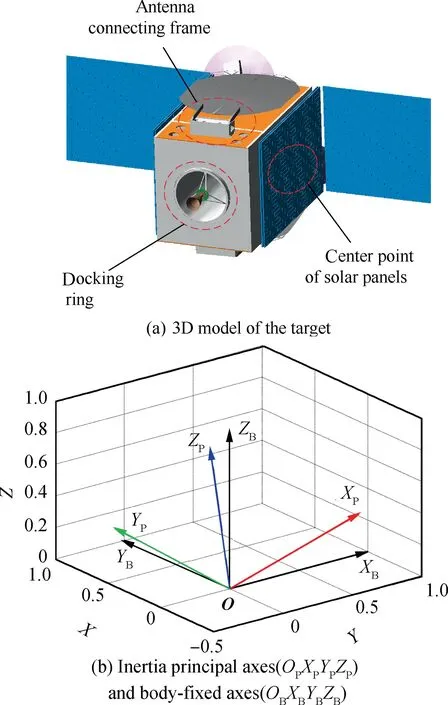
Fig. 2 Malfunctioning target to be captured.
According to the design,the principal inertia of this satellite is as follows:

The relationship between the inertia principal axis and body coordinate system is shown in Table 1 and Fig. 2(b).
It was reported that the initial angular velocities of X,Y,Zaxes are approximate to be 15.13°/s,0.05°/s and 0.12°/s when it was abandoned(observed from the ground station).According to the analysis,the rotational angular velocity of the X,Y and Z-axes of the satellite were stable at 14.364°/s, 1.224°/s and 3.4195°/s respectively under the influence of the disturbance of space environment and energy dissipation of the flexible structure. The tumbling motion was analyzed based on ADAMS software. And the simulation time was set to 600 s.Some motion states are shown in Fig. 3. As shown in Fig. 4,the motion trajectory of center point on the folded solar wing is approximate ellipsoid with variable geometric parameters.
3. Dual-arm space robotic system and capturing strategy
3.1. Dual-arm space robotic system design
Based on the above analysis, we designed a dual-arm space robotic system for capturing the tumbling target. It mainly consists of a satellite platform and two modular redundant manipulators, denoted as Arm-A and Arm-B respectively.The system configuration is shown in Fig. 5.
Both of the two arms have 7 Degrees of Freedoms(DOFs).The joints are arranged in similar structure as the Space Station Remote Manipulator System (SSRMS, also called Canadarm2),22i.e. the first three joints are orthogonal and forms the shoulder part;the fourth joint forms the elbow part,and the last three joints are orthogonal and form the wrist part. The D-H frames and corresponding D-H parameters are shown in Fig.6 and Table 2 respectively.As the manipulator has an offset in shoulder, elbow and wrist, it can achieve large rotation range for each joint.
3.2. Tumbling target approaching and capturing strategy
For the capture process, the security is very important. The security corridor and tracking trajectory need carefully designing. There are two main ways for approaching the tumbling target within the security corridor. The first strategy is that the space robot approaches the target along its spinning axis Zb, shown in Fig. 7(a). Since Zbis changing in inertia frame,the trajectory is spiral and will consume too much fuel duringthis stage. Another choice is that the space robot approaches the target along the momentum axis h, shown in Fig. 7(b).Much less fuel is required.Moreover,the control ability,safety and navigation convenience should also be considered. Therefore, the second way is adopted, i.e. the space robot is controlled to approach the target along the momentum axis h.

Table 1 Angle between the inertia principal axes and the body-fixed frame.
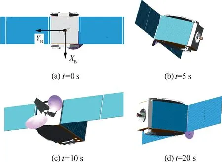
Fig. 3 Motion state of the tumbling satellite in the simulation.
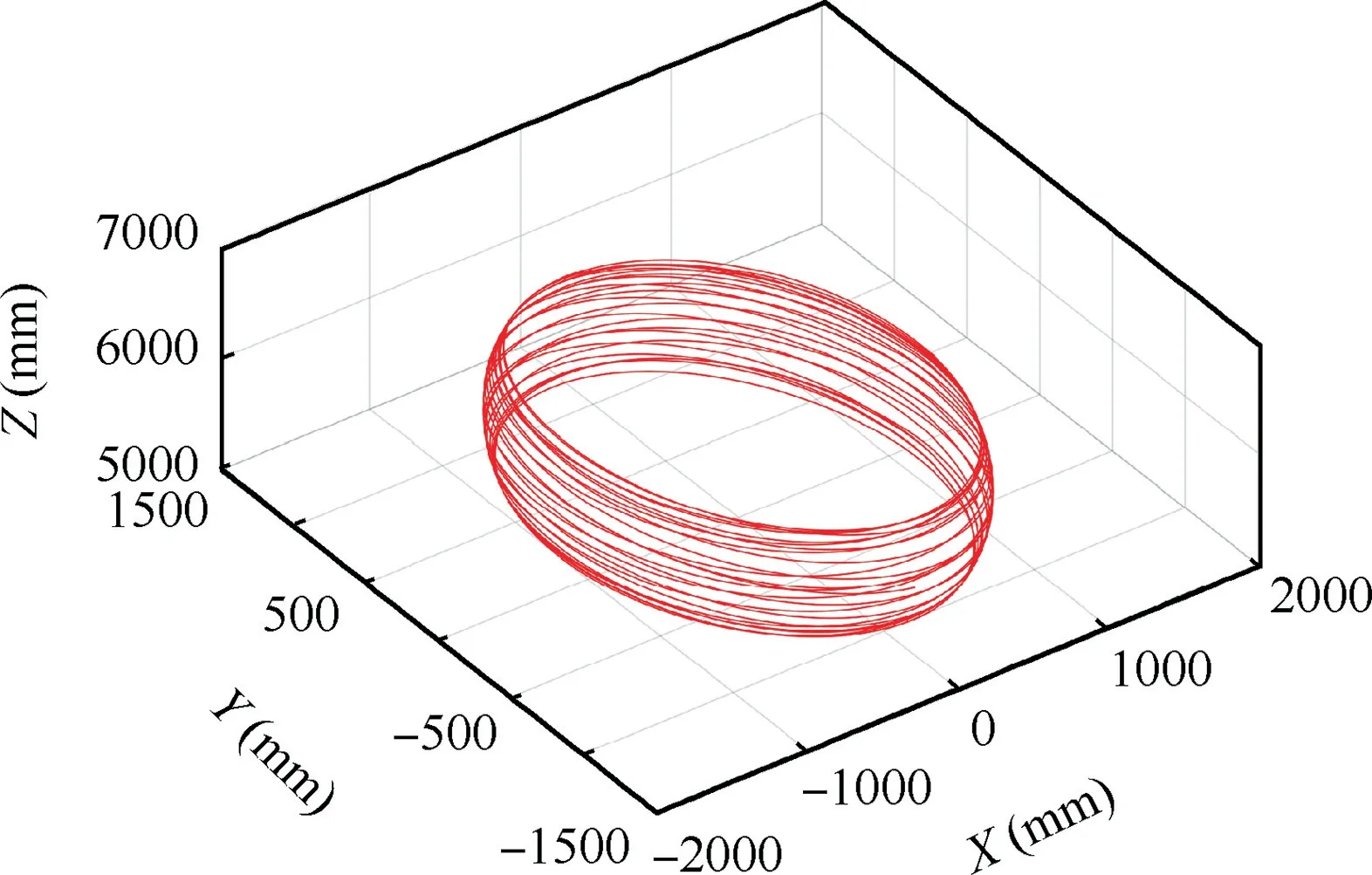
Fig. 4 The trajectory of center point on the folded solar wing.

Fig. 5 Dual-arm space robot system.
The space robot first tracks the target satellite along the direction of the momentum axis h of the target and keep appropriate relative distance (for example, 2 m distance from the upper surface of the base to the lower surface of the target).Then,the spinning platform of the space robot is controlled to spin with 15°/s to track the main rotation movement of the target along its angular momentum direction. The residual motion of the target satellite, including spinning, precession and nutation,is taken as the initial condition during capturing stage.In this paper,the satellite surface is selected as the object to be captured. As shown in Fig. 8, compared with the tumbling motion, the residual motion range of tumbling target under the spinning motion of satellite platform is much smaller. Hence, the manipulator will have much more available capture time.
4. Dual-arm coordinated planning for area-oriented capture
The concept of the area-oriented capture is shown in Fig. 9.The two arms are used to hug the main body of the target.For each arm, its end-effector is controlled to track an objective area (not fixed points on the target, but an area). When it contacts with the surface, the desired contact force is assured by the impedance control of the manipulator. The two arms are controlled in a coordinated behavior to attain the two sides almost at the same time.The possibility of capturing an uncooperative spinning object in space without a specific endeffector has been proved by the theoretical analysis and experiments.23,24
Limited by the length of the paper, the details about the pose measurement and velocity estimation are not discussed here. They are assumed to be known. Under this condition,the coordinated trajectory planning method will be presented to capture the tumbling target.
4.1. Analysis and comparison of capture tolerance
In this paper, the satellite side surfaces are selected as the objects to be captured. Generally, there exist some devices or other obstacles on the surface. Therefore, appropriate areas should be defined for capturing.For the convenience of discussion, a circular capture area, which has same entry possibility and tolerance in all directions of the plane, is taken as the example in the following parts. Without loss of generality, it is assumed that the capture area center is the geometry center of the side surface. Its radius is denoted as rC. Corresponding to the two arms, there are two capture areas on the two sides.Then, two frames, i.e. {OT1XT1YT1ZT1} and {OT2XT2YT2ZT2},are defined to represent the position and orientation of the capture areas. The origins are the center points of the circles,and the ZTi-axis(i=1,2)points to the main body of the satellite along the normal vector of the circular plane, as shown in Fig. 10.
In order to show the advantages of the area-oriented capture method, the capture tolerance of traditional method and the proposed method is compared.For the traditional method,the end-effector is controlled to track points (or objects) fixed on the target. As shown in Fig. 11(a), the capture condition is that the position and attitude deviations (denoted as Δp and Δo)between the manipulator end-effector and the target point are less than the given threshold values (εpand εoare respectively for the position and attitude), i.e.Δp‖ ‖≤εp, Δo‖ ‖≤εo. As a result, the traditional method requires high pose accuracy of the manipulator. It will take a lot of time to satisfy the capture conditions for a moving target, especially for a tumbling target.

Fig. 6 D-H frames of the modular redundant manipulator.

Table 2 D-H parameters.

4.2. Dual-arm coordinated trajectory planning
4.2.1. Large tolerance pose tracking of the two arms
The two arms are denoted as Arm-A and Arm-B respectively.Based on the visual measurement, the poses of the capture areas of the target with respect to Arm-i's (i=A, B) endeffector are assumed to be known.Here,the position and attitude of Arm -i's end- effector are respectively denoted asand0=[niE,oiE,aiE],where,is a 3-dimensional position vector of the origin of the end-effector's frame;,andare the unit orthogonal vectors denoting the directions of its XE, YEand ZEaxes. Similarly, the position and attitude of the capture area's frame are denoted asandrespectively. Then, the position deviation of the target with respect to the end-effector of the two arms are shown as follows:

The attitude deviation can be derived based on the z-y-x Euler angles and the direction cosine matrix. For small angle deviation, the direction cosine matrix can be approximately represented by the z-y-x Euler angles as follows,which is independent of the rotation order:
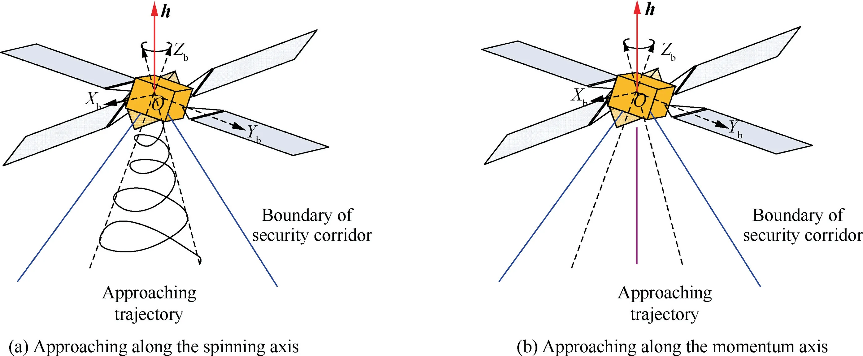
Fig. 7 Design of security corridor.

Fig. 8 Comparison of tumbling motion and residual motion.

Fig. 9 Concept of the area-oriented capturing method.

Fig. 10 Capture area on tumbling target.

where ψ,θ,φ are the small rotation angles corresponding to zy-x axes; sψ=sin ψ, cψ=cos ψ; sθ=sin(θ), cθ=cos θ;sφ=sin(φ), cφ=cos(φ).
Therefore, the attitude deviation can be calculated by the following equation:

The capture conditions of traditional method in pose level are then as follows:
Position tolerance of traditional method:

Attitude tolerance of traditional method:

According to Eqs.(4)-(8),we know that the three-axis position and attitude of the end-effector are required to be adjusted to satisfy the threshold values εpand εo,which are determined by the grasp tolerance of the end-effector. Limited by the dimension and mass of the end-effector and the objects to be grasped, εpand εowill not be very large. Therefore, when the space robot is required to capture a moving target with higher speed,the traditional methods will easily fail to track the target in limited time and workspace before the capture conditions are satisfied.16,18
For the area-oriented capture method, the position tolerance can be written as:

Comparing Eq.(9) with Eq. (7),we know that the position tolerance of area-oriented method is much larger. Moreover,only the-axis of the end-effector frame is required to approximately parallel to the normal vector of the capture surface(i.e.-axis of the capture area frame).The vector adjustment method is shown in Fig. 12. The vector ofcan be adjusted toby rotating an angle φiabout a spatial vector ρiwhich are determined by the following equations (the subscript ‘‘i” denotes Arm-i, where i=A or B):

When the angle φiis small enough, the two vectors, i.e.and,can be considered to be approximately parallel.So,the attitude tolerance corresponding to the area-oriented method can be given as:

Compared with Eq. (8), Eq. (12) intuitively illustrates the attitude deviation angle. It also shows that onlyaxis is required to be adjusted.

Fig. 11 Comparison of traditional method and area-oriented method.
From the three-axis viewpoint,the attitude deviation can be written as follows:

Eq.(13)can be used to determine the three-axis rotation of the end-effector.
Based on the above-mentioned results, the desired end velocity of Arm-i can be planned by a PD controller as follow:

In practice, the manipulator is generally not allowed to move too fast. Therefore, the upper limit of the desired velocities should be limited.In this paper,the gain matrix is set as a unit matrix,and the maximum linear and angular velocities of the end-effector are set to vem=100 mm/s and ωem=4 °/s respectively.Furthermore,it is necessary to ensure the smoothness of the start-up phase during the movement. Taking the linear velocity as an example, the following process is performed:

Fig. 12 Large tolerance area capture.

where tsis the start-up time. In this way, it is ensured that the manipulator starts smoothly and achieves the maximum synthesis velocity vemwithin 0~ts. During the capture process after the start-up, the end-effector speed of the manipulator is limited to vemwhen it is greater than vem. The processing is very important for actual engineering.
4.2.2. Coordinated motion generation of the joint angles
When the desired velocities of the end-effector of Arm-i is determined, the joint rates are then calculated according to the following equation:

In addition to the solution Eq. (17), the relative Jacobian concept can also be used to solve the coordinated motion.26One arm of the system is defined as the reference manipulator (Arm-A), and the other arm is called sevoing manipulator (Arm-B). The former provides the pose reference for the latter. The coordinated capture process can be described as shown in Fig. 13. In the ‘‘dual-arm coordinated motion planning” module, the reference manipulator is mainly used to track the capture area. At the same time, the servoing manipulator is controlled to move with the reference manipulator based on relative Jacobian. When the capture conditions are satisfied, the two arms will hug the target under coordinated compliance control.
The relationship between the two arms and the target is shown in Fig. 14, which also defines the main symbols.
There exist the following position constraints:

Similarly, the relative attitude constraints are derived as follows:

Then, the following relative motion equation is obtained:

where, vRand ωRare the relative velocities of the servoing manipulator's end-effector with respect to those of the reference manipulator's end-effector; ˙ΘAand ˙ΘBare the joint rates of Arm-A and Arm-B respectively;JR∈R6×2n(n is the number of the degree of freedom of each manipulator) is the so called relative Jacobian matrix, which can be obtained by arranging

Fig. 13 The coordinated capture control process.
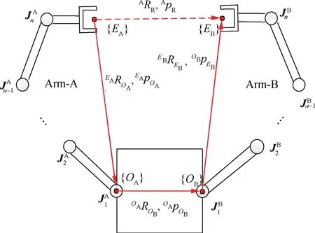
Fig. 14 Relationship in dual-arm coordinated operation.
and simplifying the differential equations and is written as follows:


When the desired velocitiesandare determined by Arm-B with respect to that of Arm-A can be computed:

According to Eqs. (23) and (26), we can calculate the desired joint velocities corresponding to dual-arm coordinated motion.However,in order to guarantee the desired motion of each arm, we introduce the null-space projection method.27Given the desired motion of the selected reference arm Arm-A, the corresponding desired joint angular velocity can be obtained by the following equation:

Furthermore, the desired relative motion between the two arms can be realized in the null space of the reference arm as follows:


Fig. 15 Pose deviation between the end of Arm-A and the capture point by fixed-points oriented capture.

Fig. 16 Pose deviation between the end of Arm-B and the capture point by fixed-points oriented capture.

Fig. 17 Pose deviation between the end of Arm-A and the capture point by area oriented capture.
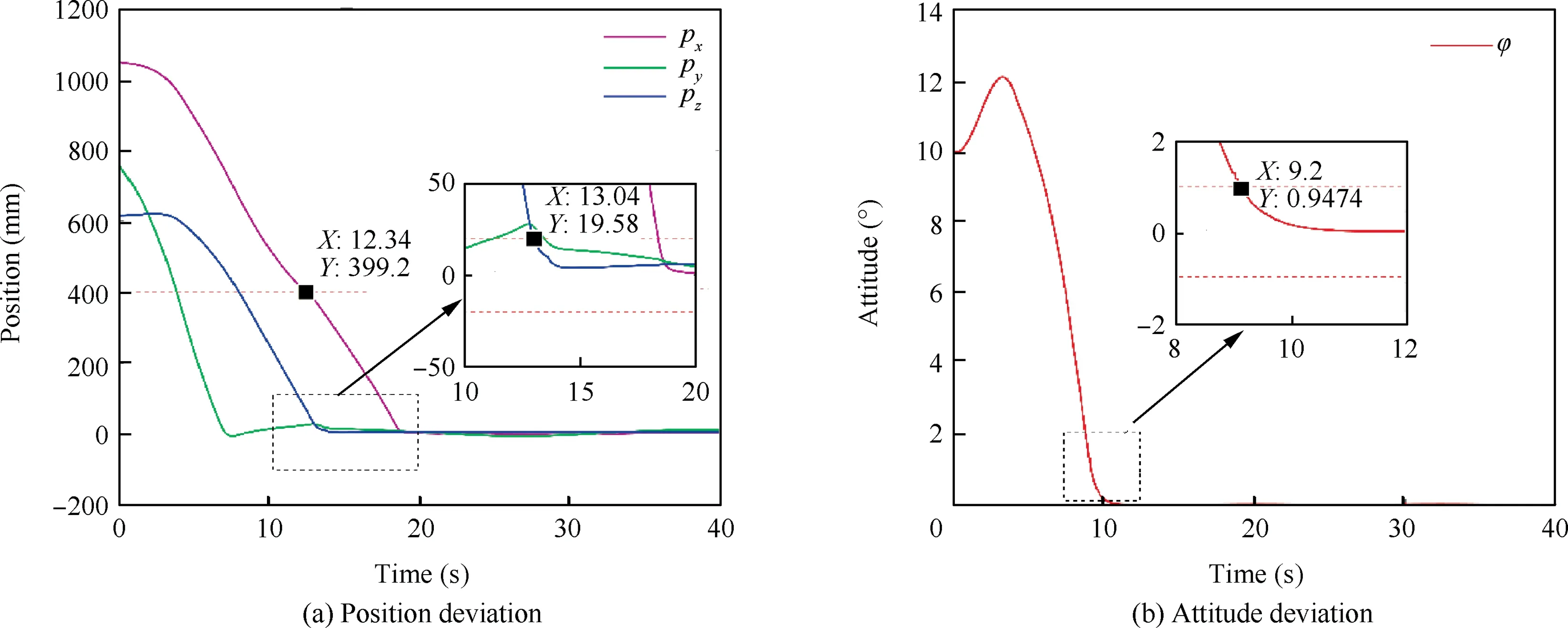
Fig. 18 Pose deviation between the end of Arm-B and the capture point by area oriented capture.

Fig. 19 System stage during capturing.

Table 3 Analysis of simulation results.
Therefore, the desired joint angular velocities of two arms can be obtained by adding Eqs. (27) and (28).
5. Simulation
To verify the proposed method, an interactive simulation model of dual-arm space robot and target satellite is created based on ADAMS and MATLAB/Simulink software. The multi-body dynamics model is built in ADAMS,and the planner and controller are realized in MATLAB/Simulink. Then,the fixed-points oriented capture method and the AOC method are compared through simulations under the same conditions.The attitude deviation is calculated from Eq. (6) in the fixedpoint oriented capture method. However, it is calculated from Eq. (13) in the area oriented capture method. All the simulation results are obtained by using the same planning and control method in Section 4.2.2.
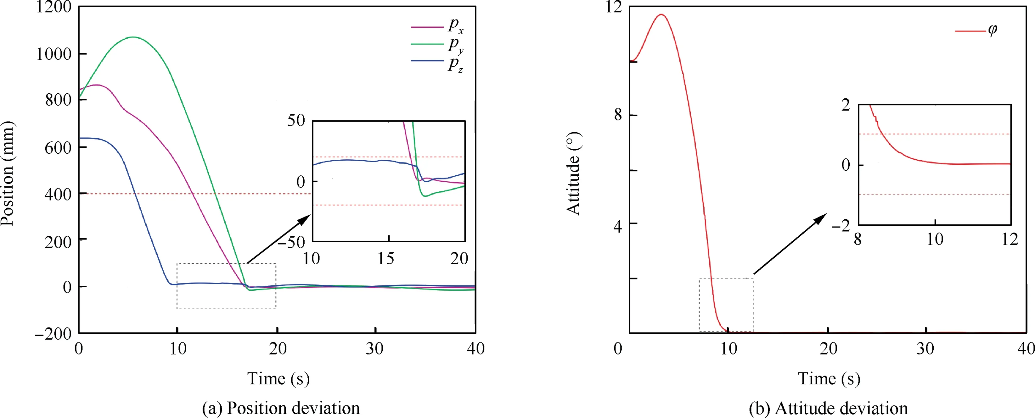
Fig. 20 Pose deviation between the end of Arm-A and the capture when the base is actively controlled.

Fig. 21 Pose deviation between the end of Arm-B and the capture when the base is actively controlled.
As described in Section 3, the space robot first tracks the target satellite along the direction of the momentum axis and then keep appropriate relative distance. Then, the spinning platform of the space robot is controlled to spin with 15°/s to track the main rotation movement of the target. The residual motion of the target satellite, including spinning, precession and nutation, is taken as the initial condition during capturing stage.The base is assumed inertially fixed in Sections 5.1 and 5.2.
5.1. Fixed-points oriented capture method
The two frames, {OT1XT1YT1ZT1} and {OT2XT2YT2ZT2} are respectively taken as the reference objects to be captured.The traditional fixed-points oriented capture method is then used to capture the target.The threshold values of the position and attitude are set as follows:

According to the simulation results, the curves of the relative pose from the end-effector frame to the target frame are shown in Figs. 15 and 16, corresponding to Arm-A and Arm-B respectively.
It can be seen that Arm-A meets the position threshold value (i.e. 20 mm) of the end-effector in 18.38 s; the attitude threshold value(i.e.1°)is satisfied in 10.14 s.On the other side,Arm-B meets the position tolerance of the end-effector in 18.80 s,and the attitude tolerance in 9.36 s.Therefore,the time of dual-arm coordinated capturing and locking the target satellite is 18.80 s.
5.2. Area-oriented capture method
Considering the dimension of the target and the devices on it,we choose a circle whose radius is 400 mm as the capture area.Then, the area-oriented method is used to capture the target under the same conditions as those of the fixed-points oriented capture method. According to the simulation, the pose deviations between the manipulator's end-effector and the target point during capturing are shown in Figs. 17 and 18.

Fig. 22 Base disturbance during the capture process when the base is actively controlled.
It can be seen that Arm-A meets the position tolerance(400 mm for the area capture)in 15.14 s.The attitude tolerance(1° between ZEand ZT) is satisfied in 8.65 s. On the other hand, Arm-B meets the position and attitude tolerance in 13.04 s and 9.20 s respectively. Therefore, all capturing conditions of dual-arm space robotic system are satisfied in 15.14 s.Compared with traditional method, the time used for capturing is largely reduced.The system state in ADAMS simulation environment during capturing is shown in Fig. 19.
5.3. Comparison and discussion
Based on the simulation results above, the capture time and tolerance of the two capture methods are respectively shown in Table 3. Obviously, the AOC method has greater advantages over fixed-points oriented capture method, especially on capture time and tolerance. Actually, the capture conditions of AOC are simplified as: the position of the end-effector is within the capture area, and the approaching direction of the manipulator is perpendicular to the surface.Therefore, the AOC method has much more weaker constraints, higher efficiency and shorter time for tumbling target capturing. The capture time is reduced by 19.5%.
In order to show the robustness of the proposed areaoriented capture method, we further perform a simulation in which the base is actively controlled by a PD controller instead of inertially fixed.The simulation results are shown in Figs.20 and 21. The base disturbance during the capture process is shown in Fig. 22. Note that, the results will be much better if the dynamics feedforward compensation part is introduced into the controller. It can be seen that the dual-arm space robot can stably track and capture the tumbling target by the proposed method even with the base disturbance.
The area oriented dual-arm coordinated capture method proposed in this paper mainly focus on the trajectory planning of dual-arm space robot in pre-capture phase.In order to support our research, it is assumed that the desired capture area can be determined by the detailed visual servo information.For a complete capture task, the contact phase and postcapture phase should also be addressed. However, there are a lot of difficulties in the last two phases, such as the coordinated force control without losing the target in contact phase,28and the compounded system stabilization with unknown dynamic parameters in post-capture phase. All the above questions need a further research and solution.
6. Conclusions
(1) An area oriented dual-arm coordinated capture method is proposed in this paper,which has much larger capture tolerance, shorter capture time and higher efficiency than those of fixed-points oriented capture method.
(2) The motion equation of the tumbling target is established, based on which, the dynamic properties are analyzed.Furthermore,the corresponding capturing and tracking strategies are presented.
(3) An area rather than fixed points/devices is taken as the object to be tracked and captured. Then, a dual-arm coordinated trajectory planning method is presented for tracking the capturing area.
(4) An interactive simulation model of dual-arm space robot and target satellite is created based on ADAMS and MATLAB/Simulink software. The simulation results show the correctness and effectiveness of the proposed method.
Acknowledgements
This work was supported by the National Natural Science Foundation of China (No. U1613227), Guangdong Special Support Program (No. 2017TX04X0071), Self-Planned Task of State Key Labora-tory of Robotics and System (HIT) (No.SKLRS201817B),and Shenzhen Key Lab Fund of Mechanisms and Control in Aerospace(No.ZDSYS201703031002066).
杂志排行
CHINESE JOURNAL OF AERONAUTICS的其它文章
- Heading control strategy assessment for coaxial compound helicopters
- An adaptive integration surface for predicting transonic rotor noise in hovering and forward flights
- An algorithm to separate wind tunnel background noise from turbulent boundary layer excitation
- Simulation of mass and heat transfer in liquid hydrogen tanks during pressurizing
- Leakage performance of floating ring seal in cold/hot state for aero-engine
- Six sigma robust design optimization for thermal protection system of hypersonic vehicles based on successive response surface method
