Heading control strategy assessment for coaxial compound helicopters
2019-10-26YeYUANDouglasTHOMSONRenliangCHENRichardDUNLOP
Ye YUAN, Douglas THOMSON, Renliang CHEN, Richard DUNLOP
a National Key Laboratory of Rotorcraft Aeromechanics, Nanjing University of Aeronautics & Astronautics, Nanjing 210016, China b University of Glasgow, Glasgow G12 8QQ, United Kingdom
KEYWORDS Coaxial compound helicopter;Control strategy;Handling qualities;Helicopter flight dynamics;Helicopter performance
Abstract The coaxial compound helicopter has two possible strategies for heading control:collective differential and rudder deflection. A flight dynamics model is developed to assess the effect of different heading control strategies.This includes the trim characteristics,steady flight performance,controllability, and manoeuvrability. The trim study demonstrates that heading control strategies are less influential on trim results,and the steady flight performance is also not significantly affected by the heading control strategy adopted.The controllability analysis shows although heading bandwidth and phase delay results at various speeds with different heading control strategies are all satisfied, the control derivative of the collective differential decreases as speed increases, and its heading aggressive agility is degraded into Level 3 in high-speed flight.In addition,using collective differential would lead to severe heading-rolling coupling as forward speed increases. On the contrary,the control derivative and aggressive agility of the rudder deflection is improved with forward speed, and there is no evidence of heading-rolling coupling. Finally, the transient turn Mission-Task-Element (MTE) is utilized to investigate the heading manoeuvre characteristics in different heading control strategies, which indicates that the collective differential would add the amplitude of control input and the power consumption during this MTE.
1. Introduction
The coaxial compound helicopter has gained a lot of research interests in recent years due to its high-speed performance1,2and outstanding cruise-efficiency.3The coaxial rotor system does not require a tail rotor for anti-torque. Thus, the coaxial compound helicopter usually utilizes differential collective or rudder deflection to control heading. The choice of strategy leads to a significant difference in heading control characteristics obtained, and it is known that the heading stability of the coaxial compound helicopter is worse than that of the conventional helicopter with a tail rotor,4which puts forward higher requirement for the heading control strategy.
The conventional coaxial helicopter usually utilizes collective differential to control heading, which is efficient in hover and low-speed forward flight.5However, the control power of the collective differential dramatically decreases due to the reverse flow.6Blade elements in the reverse flow area are usually stalling and differential collective cannot provide sufficient heading moment when the reverse flow region is relatively large.7This phenomenon is more significant in terms of the coaxial compound helicopter because of Lift-Offset (LOS).LOS is used to evaluate the effective lateral displacement of the lift vector for each of the coaxial rotors from the hub centre. A coaxial rotor with reasonable LOS can attain good efficiency by operating with more lift on the advancing side than the retreating side of the rotor disc.8-12The imbalance between advancing and retreating blade usually leads to more loss of the collective differential's control power in the high-speed range. In addition, when the differential collective is utilized,the LOS effects on the upper and lower rotors are no longer the same, which may lead to imbalance roll moment from the coaxial rotors.13It would, in turn, affect the rotor performance,14which implies that the differential collective may lead to extra power consumption in manoeuvring.Due to these disadvantages,the rudder deflection could be a potential way for coaxial compound helicopters to control the heading moment.However, rudder deflection is ineffective in the hover and at low forward speed due to insufficient dynamic pressure at the vertical tail.15Moreover, the extra design of the rudder deflection and its control system would add the structural weight of the helicopter.Therefore,the coaxial compound helicopter has unique heading characteristics and control features.Thus, there is a need to investigate the most effective strategy for controlling the heading of these aircraft.
There has already been some research on the heading characteristics and heading control strategies of the coaxial compound helicopters. Ruddell et al.16,17investigated the heading characteristics of the coaxial compound helicopter based on the flight test of the XH-59A helicopter with various heading control strategies. The controllability results showed that collective differential would create a rolling moment that requires an extra lateral stick input to balance, and that its control power decreases with forward speed. Thus, the collective differential is gradually replaced by the rudder deflection with forward speed increase to provide the heading control moment. Ferguson and Douglas18,19calculated the heading control derivative with differential collective, and the results demonstrated that the direction of heading moment after a positive input of the collective differential would be reversed in high-speed flight.In the research of Wittmer,20the combination of the differential collective and rudder deflection was utilized to control the heading moment of a coaxial compound helicopter. This method was based on a series of databases to decide the heading control strategies. The construction of these databases needs a great deal of simulation and flight test.According to all of the above,the heading control of the coaxial compound helicopters still requires further development.The trim characteristics, flight performance, and handling qualities should all be taken into consideration.
In light of the preceding discussion,this article briefly introduces the existing flight dynamics model of the coaxial compound helicopter. Also, the inverse simulation method and the transient turn MTE are illustrated for heading manoeuver assessment. The trim characteristics and performance with two different heading control strategies,the differential collective and the rudder deflection, are analyzed. Then, the paper assesses the other flight dynamics characteristics of the coaxial compound helicopter in these two heading control strategies,such as the control derivatives,coupling feature,bandwidth&phase delay,and aggressive agility.Finally,in the manoeuvrability evaluation,the transient turn MTE is evaluated with the differential collective and the rudder deflection,respectively.
2. Methodology
2.1. Model overview
The coaxial compound helicopter flight dynamics model utilized in this article is based on the model described by Yuan et al.,21which has been verified with flight data and other simulation results. The model is composed of five parts: rotor,propeller, horizontal tail, vertical tail, and fuselage.
In the rotor part,a conventional disc-type model is used to calculate the forces and moments.The induced velocity model is based on the Pitt-Peters dynamic inflow model22and assumes that the induced inflow of the lower rotor does not affect the upper rotor's ability to generate thrust, and the rotors are so sufficiently close together that the wake from the upper rotor does not fully develop.18In addition,the rotor model ignores the pitching and lagging Degree of Freedoms(DOFs), assuming that the flap motion has the most influence on the flight dynamics characteristics.To simulate the flapping motion more precisely, the model utilizes the equivalence method of the combination of equivalent flapping offset and flapping spring.23,24An airfoil aerodynamic look-up table is utilized in aerodynamic load calculation of the rotors.
The propeller part is similar to the rotor model except that there is no flapping motion in the propeller blade.
The fuselage model uses data from wind tunnel tests.25The force and moment coefficients of the wind tunnel test are dependent on the fuselage angle of attack and sideslip.
A 2D representation of the horizontal and vertical tail using strip theory is incorporated into the model. The lift and drag coefficients can be obtained from a 2D airfoil aerodynamics look-up table with given angle of attack and sideslip. Also, a rudder deflection correction on the vertical tail is added in the vertical tail aerodynamic model.26
The flight dynamics model of the coaxial compound helicopter contains 21 DOFs, including 6 DOFs of the fuselage rigid motions, 6 DOFs of the induced velocities of the coaxial rotor,6 DOFs of the flapping motions of the upper and lower rotors, and 3 DOFs of the induced velocities of the propeller.The state-space equations of the model can be expressed as


where xlinear= [u,v,w,p,q,r,φ,θ]Tand ulinear= [θ0,θ1c,θ1s,θ01,βru]Tare the state and control vectors in linearization in this article,respectively.The state and control vectors are perturbations from the trimmed state. The system matrix A contains the stability derivatives whereas the control derivatives define the control matrix B.
The aircraft data used in this article is based on the XH-59A helicopter. The primary data for the XH-59A helicopter is shown in Table 1.16,17,25
As the XH-59A helicopter utilized an auxiliary propulsion unit rather than a propeller to provide the thrust at the highspeed range,this article uses a propeller instead,which is more in line with the development of coaxial compound helicopters in recent years. The parameters of the propeller are shown in Table 2.18
2.2. Trim strategies
In this article, the trim characteristics, performance, and handling qualities will be analyzed. The starting point of these analysis is the trim process.However,there are four additional differences in the trim strategies between the coaxial compound helicopter and the conventional helicopter. Except for the control strategies of the heading that will be investigated in this article,they are the propeller control strategy,the rotor speed, and the LOS setting.
The auxiliary propeller can be used to provide thrust in the high-speed flight range to offload the rotor and improve the performance. The propeller thrust is therefore an additional unknown trim variable in the trim process. Thus, a fuselage pitch attitude schedule18is used to trim the propeller collective at various speed ranges.
The coaxial rotor speed should be slowed down to avoid the compressibility effect at the advancing blade tip in high-speed flight. Therefore, a pre-scheduled rotor speed is set as Eq. (3),which is27

Table 1 XH-59A helicopter parameters.16,17,25

Table 2 Parameters of compound propeller.18

where Ω is the rotor speed; vfis the forward speed.
LOS has a significant influence on the efficiency of the coaxial rigid rotor. Its value can be defined as

where ΔMxis the upper rotor rolling moment; T is the total rotor thrust; R is the rotor radius.
LOS can be regulated by differential lateral cyclic pitch,θdc.Thus,θdcis determined to be a variable in the trim process,and its value is scheduled to follow Eq. (5) with respect to the forward speed.28

The aim of Eq.(5)is to improve the efficiency of the coaxial rotor system at various flight velocities. No lateral offset is required in the hover flight state, and increasing LOS could avoid retreating blade stall in high-speed flight.27It should be noticed that this LOS control strategy can only guarantee the efficiency of the upper and lower rotors when the thrust of both rotors are more alike. In other words, when there is a large input of the collective differential, the coaxial rotors'performance would decrease even if LOS defined in Eq.(4)still holds its original value according to Eq. (5). The power consumption may be no longer the optimal value at this time.
In terms of the control strategy for the heading moment,both the differential collective and the rudder deflection are utilized respectively to analyze their difference on the flight dynamics characteristics of the coaxial compound helicopter.
2.3. Inverse simulation
The US military handling qualities requirements for rotorcraft,ADS-33E-PRF,29specifies a series of Mission-Task-Elements(MTEs) to be flown in order to assess the manoeuvrability of the rotorcraft. Inverse simulation can be an efficient method to investigate flight characteristics when flying these MTEs.This method is explained widely in the literature by various authors.30-34Therefore, only a brief overview of this method is shown in this article.
The forward time response solution of the rotorcraft is readily available when the flight dynamics model is constructed. The inverse simulation can be represented as a ‘‘trim process” with respect to each time step through a predefined trajectory or manoeuvre. At the new time increment, the control input must be varied to ensure the correct flight path,which is given by the mathematical description of the MTE or other manoeuvres. The given mathematical description will be discussed later in this article.
In order to process the inverse simulation algorithm, this article executes the following steps with respect to the characteristics of the coaxial compound helicopter:
(1) Calculate trim control input
The trimmed states correspond to steady level flight with the body accelerations and the attitude rates equal to zero,which is the initial point of the MTE manoeuvres. The trim variables of the conventional helicopters are equal to the trim target equations. However, the coaxial compound helicopter has redundant control inputs. Thus, the trim strategies mentioned above are utilized here to determine the initial point of MTE.
(2) Define manoeuvre
The manoeuvre can be defined simply by polynomial representations of position or other flight path variables. This is then discretized into a series of discrete time points.The redundant control of the coaxial compound helicopter may affect the definition of the manoeuvre as they may need additional polynomials to obtain their control inputs with respect to the time step. In this article, the main objective is to assess the heading control characteristics. Therefore, the lateral cyclic pitch differential, and the rotor rotational speed are fixed at the value of the trimmed state.The propeller collective is used to maintain the pitch attitude at zero during the manoeuvring.
(3) Calculate control vector
This inverse simulation model uses a Newton-Raphson technique to calculate the controls required in order to maintain the helicopter's states in accordance with the manoeuvre mathematical description.This process is repeated throughout each time step until the manoeuvre has been completed.
2.4. Transient turn MTE
According to the specification of the rotorcraft handling qualities ADS-33E-PRF, the aim of the transient turn MTE is to ensure that handling qualities do not degrade during aggressive manoeuvring in all axes and to check for undesirable coupling between pitch,roll and yaw.This MTE is appropriate to evaluate the different heading control methods on the handling qualities of the coaxial compound helicopter, especially in high-speed flight. The mathematical definition of this MTE is developed by Thomson and Roy,35and the brief introduction is shown below.
When executing the transient turn MTE, the helicopter needs to accomplish a 180° directional change in flightpath in 10 s at a forward speed of 120 knots (approximately 60 m/s) to obtain the Level 1 handling qualities rating.Meanwhile,the altitude change should be limited and the attitude ought to be wings-level after the manoeuvre. Therefore,the mathematical description of the transient turn MTE can be defined by Eqs.(6)-(9)according to the related requirement on ADS-33E-PRF.

where U is the forward speed in body axes; γ is the glideslope angle;β is the sideslip angle;χ is the track angle.The next step is to define the track angle distribution f(t) throughout the manoeuvre by applying the related boundary conditions.Fig. 1 shows the track angle derivative ˙χ distribution which relates to the desirable standards set in the specification,where the manoeuvre is divided into four stages, including the starting stage (t0≤t <t1), turning stage (t1≤t <t2), ending stage(t2≤t <t3), and stable stage (t ≥t3).
The boundary conditions of the transient turn MTE are shown in Table 3 based on the distribution in Fig. 1, and the reason for the boundary condition setting is to guarantee that the aircraft can smoothly accomplish the manoeuvre without the discontinuity in control input.
With the boundary conditions, the transient turn MTE is assumed to be split into four segments, and in each of these sections, a fifth-order polynomial is formed to describe the turn rate throughout the manoeuvre:
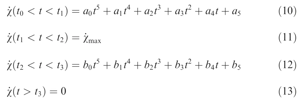
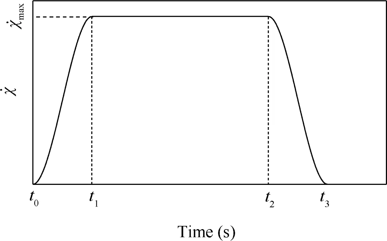
Fig. 1 Desirable track angle derivative throughout transient turn MTE.
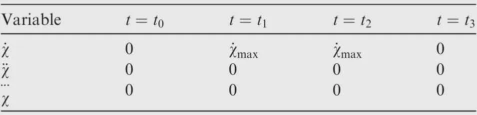
Table 3 Turn rate boundary condition.
where the coefficients in Eqs. (10) and (12) are determined by applying the boundary conditions between the start and end time of that manoeuvre segment according to Table 1. Thus,the maximum turn rate can be determined by the change of the direction (180° in transient turn MTE) and the time requirement (10 s in transient turn MTE). With the mathematical description of Eqs.(6)-(13)and the inverse simulation method,the control inputs of the MTE are obtained with each time step.
3. Steady flight investigation
3.1. Trim characteristics
Fig. 2 shows the trim results from hover to 100 m/s forward speed with two heading control strategies,which are the collective differential and the rudder deflection.
As demonstrated in Fig. 2, when the rudder deflection is utilized as heading control input, the trim cannot be achieved when the forward speed is relatively low due to the inadequate local velocity on the vertical tail to provide equilibrant moment. This is also the reason why the rudder deflection is significantly high at the beginning. According to Fig. 2(a)and (c), the collective differential has a slight influence on the lateral trim characteristics. Usually, the roll moments of the upper and lower rotors are equal in trim state. When the collective differential takes effect,these moments would be different because of LOS. This effect is demonstrated in Fig. 3.

Fig. 2 Trim characteristics.

Fig. 3 Effect of LOS on lateral trim characteristics.
When the collective differential input is close to zero, LOS on the upper and lower rotors would be similar to each other.The coaxial rotors are in balance in terms of the rolling moment (the solid line in Fig. 3). Once there is an input of the collective differential,the lift of the upper and lower rotors is different (the dashed line in Fig. 3), and LOS would also change separately. Both of these effects lead to a significant rolling moment to the helicopter. Thus,the lateral cyclic pitch has to compensate the rolling moment produced by the collective differential. The rolling attitude also changes with the lateral cyclic pitch as the high rigidity of the coaxial rotors.
The trim results illustrate that the different heading control methods have a little effect on the trim characteristics of the longitudinal and vertical channels. Only slight differences occur in the mid-speed forward flight due to the extra aerodynamic drag from the rudder deflecting or the influence of the collective differential on LOS.
3.2. Power required
The power required for various heading control strategies is shown in Fig. 4.
The power required results in different heading control strategies are alike. Only at mid-speed forward flight range(20 m/s -40 m/s forward flight), the power consumption of the rudder control is a little higher than that of the collective differential because of the extra profile power from the rudder deflection and the effect of LOS on the performance of the coaxial rotors, which can be observed in Table 4.
Based on Table 4, around 4% of the overall power consumption can be reduced by using the collective differential at the mid-speed forward flight range (20 m/s). However, the difference in power consumption between two heading strategies is only 0.2% in high speed (100 m/s).
According to the trim and performance analysis, it is hard to detect the difference between two heading control strategies as the heading moment that needs to balance is minimal in trim flight. In order to investigate the heading control in a more comprehensive perspective, the controllability characteristics investigation would be progressed.
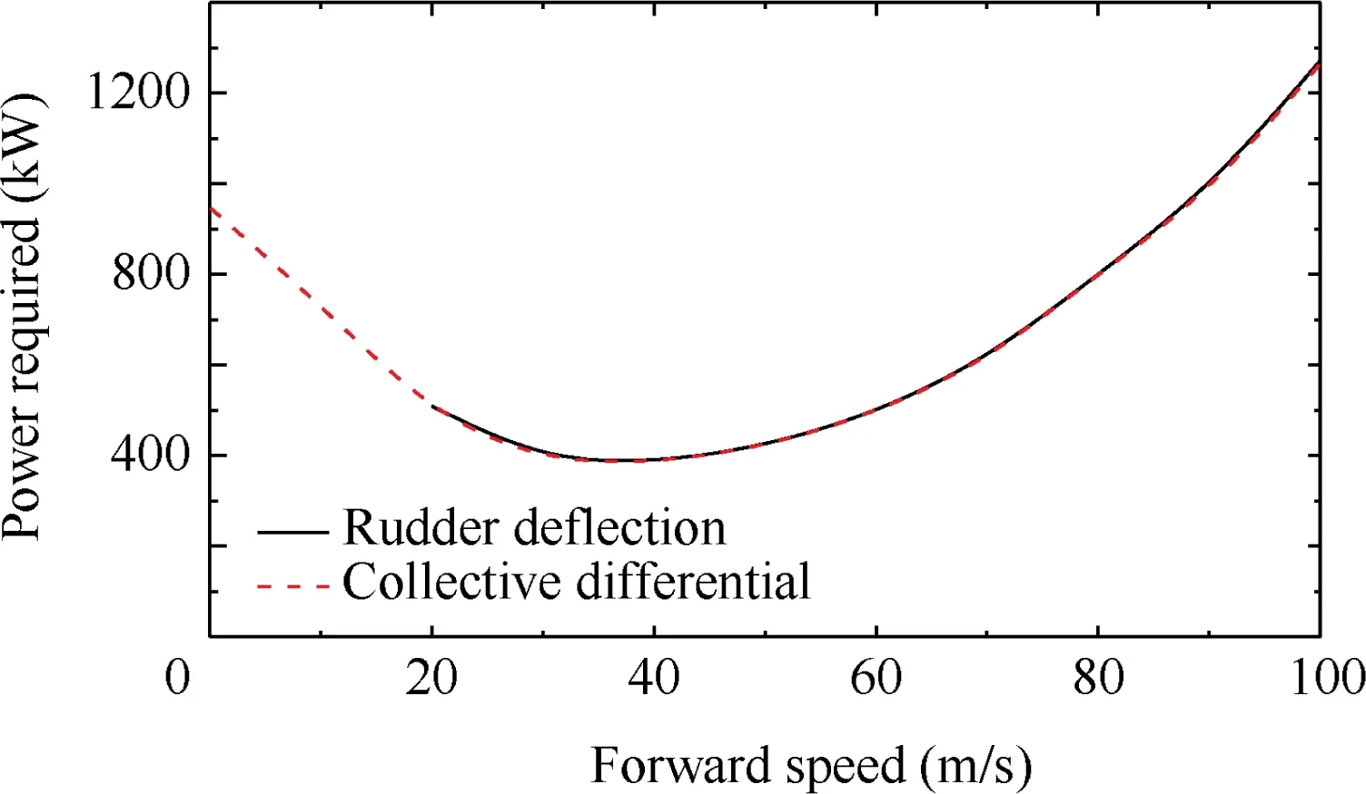
Fig. 4 Power consumption.

Table 4 Power consumption comparison.
4. Controllability investigation
In the controllability investigation,the heading control derivative, heading-rolling coupling characteristics, heading bandwidth and phase delay, and aggressive agility are calculated with the heading control strategies of the collective differential and the rudder deflection, respectively. Meanwhile, the bandwidth and phase delay and the aggressive agility are also assessed with respect to the handling qualities requirements for military rotorcraft (ADS-33E-PRF).
4.1. Heading control derivative
The heading control derivative directly demonstrates the capability of providing heading moment with given control strategy. These derivatives are calculated using the linearization algorithm, Eq. (2). Therefore, the heading control derivatives with the collective differential Nθ01and the rudder deflection Nβruare shown in Fig. 5.
According to Fig. 5, the heading control derivative with respect to collective differential is reducing as forward speed increases.On the other hand,the derivative with rudder deflection shows a different trend.The heading control moment produced by the rudder deflection is dependent on the dynamic pressure at the vertical tail. Thus, its control derivative increases with forward speed.
The change of the collective differential control derivative is influenced by the rotor aerodynamic characteristics. Firstly,the reverse flow area becomes larger as forward speed increases.It affects this control derivative as the blade element in the reverse flow area would no longer provide much airfoil element drag, and in other words, the heading moment. In addition, the coaxial compound helicopter utilizes the auxiliary propeller to provide the thrust in high-speed flight, and the coaxial rotor is offloaded at this flight range,which consequently reduces the heading control derivative of the collective differential further.
My first Thanksgiving in prison, I refused to eat. My first birthday I spent alternating between rage and feeling more sorry for myself than ever before. On Christmas, I wouldn t even get out of bed. I stayed under the covers to hide the tears I cried all day.
By comparing these two kinds of heading control methods,the rudder deflection produces more heading moment than the collective differential with the same control input in mid- to high-speed forward flight range (above 30 m/s).
4.2. Heading-rolling coupling (rolling derivative with heading inputs)

Fig. 5 Heading control derivative.
According to the trim analysis above,LOS experienced by the coaxial compound helicopter may lead to strong coupling between heading and rolling channels, which influences the handling qualities. Therefore, the rolling coupling derivatives Lθ01,Lβruwith different heading strategies at various forward speeds are shown in Fig. 6.
As indicated in Fig. 6, the coupling phenomenon is more severe when the collective differential is used and it increases with forward speed.It is also clear from Fig.6 that the rudder deflection creates little rolling-heading coupling.
Applying collective differential changes the lift from the upper and lower rotors and so would influence LOS on the upper and lower rotors. According to the analysis above, the differential collective would lead to the imbalance rolling moment of the coaxial rotors to the vehicle. As LOS increases with forward speed, the coupling is more severe.
On the other hand,the coupling from rudder deflection can be provided by the lateral moment of the vertical tail. However, the X-direction distance of the vertical tail to center of gravity is relatively small according to Table 1. This coupling of the rudder deflection is minor at all speeds.
Thus,this coupling caused by the collective differential may lead to a handling qualities problem,which would be evaluated in the manoeuvrability investigation.
4.3. Bandwidth and phase delay
To obtain the bandwidth and phase delay,the dynamic models of the control mechanism and the actuator are needed,and this article utilizes a standard transfer function of Eqs. (14) and(15) to simulate.36

The bandwidth and phase delay results with different heading control strategies can be calculated from Fig. 7, which are shown in Table 5. The handling qualities rating assessment based on the requirement in ADS-33E-PRF is also added in Table 5.

Fig. 6 Rolling derivatives with heading input.

Fig. 7 Bandwidth and phase delay results.
As indicated in Fig. 7 and Table 5, the heading bandwidth and phase delay all satisfy the Level 1 requirement at various speed ranges for both heading control strategies. The results illustrate that the coaxial compound helicopter is unlikely to experience strong Pilot-Induced-Oscillation (PIO) and it has excellent tracking characteristics in heading with small amplitude response.Also,it is worth noting that when using the collective differential, the bandwidth and phase delay would be worse than that of the rudder deflection due to its coupling characteristics.
4.4. Aggressive agility
Aggressive agility in heading relates to the ability of the helicopter to operate safely with speed and precision; a helicopter with good aggressive agility can not only yaw rapidly but reach its maximum heading angular velocity rapidly also.37According to the requirement of heading aggressive agility in ADS-33E-PRF, this article utilizes the flight dynamics model to calculate the heading response experienced 1 second after an abrupt step displacement of the two heading controls(collective differential and rudder deflection). The results are shown in Table 6.
Table 6 demonstrates the aggressive agility results with different heading control strategies. The aggressive agility in heading using collective differential is reduced with forward speed.At the flight range around 40 m/s,the qualities rating is in Level 1, but when the forward speed increases to 100 m/s,the rating is degraded to Level 3 as the control power of this heading control is not sufficient to achieve satisfactory heading control characteristics, which could be proved by the control derivative results in Fig. 5.
Meanwhile, the aggressive agility using the rudder deflection strategy increases with forward speed. The control powerof this heading control is dependent on the dynamic pressure at the vertical tails. Therefore, the heading control aggressive agility is improved as forward speed increases, and achieves the requirement of Level 1 at the speed range of 100 m/s.

Table 5 Bandwidth and phase delay results.

Table 6 Aggressive agility results.
5. Manoeuvrability analysis
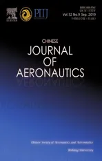
The manoeuvrability analysis is also important to ensure that a new helicopter will be safe in achieving its operational goals.Using MTE manoeuvre,such as the transient turn,to evaluate flying qualities is an effective method to assess the heading characteristics in manoeuvre.This article utilizes inverse simulation to analyze the transient turn MTE according to the requirement of ADS-33E-PRF, which has been introduced above. The control inputs during this MTE with different heading control strategies are shown in Fig. 8.
According to the results, both of these heading strategies could achieve this MTE within Level 1 boundary conditions.However,these two heading control strategies exhibit different heading control characteristics.
Firstly, the collective differential approach requires more heading control inputs than that of the rudder deflection approach. As indicated in the controllability investigation,the control power of the collective differential is relatively low at this flight range (around 60 m/s). Thus, more pedal is needed to achieve this manoeuvre within the given time limit.However, the control power of the rudder deflection is sufficient at this flight range, and the pedal input is smoother.
Heading control needs to be in cooperation with the lateral control to achieve the transient turn MTE.Comparing the two heading control strategies, in terms of lateral cyclic pitch, the rudder deflection results are significantly less than those of the collective differential.This is due to the coupling characteristics as illustrated above. The input of the differential collective would produce the rolling moment of the helicopter,which means that more lateral cyclic pitch is necessary to balance the vehicle.On the contrary,the rudder deflection cannot induce this coupling, and the amplitude of the lateral cyclic pitch is consequently much less. In addition, the bank and track angle response results during the MTE are demonstrated in Fig. 9.
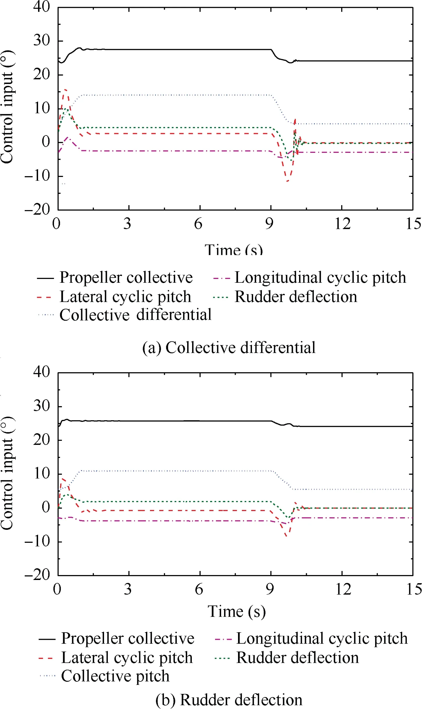
Fig. 8 Inverse simulation results of transient turn MTE.
The bank and track angle trends of different heading control strategies are alike, which means that both control strategies execute this MTE in a similar way.The helicopter needs to tilt sideward to produce more side force for the helicopter because the centripetal force is needed in transient turn MTE.
Fig.8 also demonstrates the difference in collective pitch in manoeuvring. The increment of the collective pitch using collective differential is significantly larger than that of the rudder deflection.That is because the collective differential affects the performance of the coaxial rotor. The collective differential separately changes the collective pitch on the upper and lower rotor, which alters LOS and degrades the aerodynamic efficiency of the coaxial rotor system.The change in the collective pitch is much smaller when using the rudder deflection. The control of the rudder deflection does not change LOS of the coaxial rotor to a large extent. So as to say, the use of the rudder deflection could guarantee the aerodynamic characteristics of the rotor during the transient turn MTE and consequently make the collective pitch input less aggressive.

Fig. 9 Bank angle response simulation results.
The change of LOS when using the differential collective would also influence the propeller collective results,as demonstrated in Fig. 8. The propeller collective increases quicker when the differential collective is adopted. The reduction of rotor performance would not only add the collective pitch but also increase the drag of the rotor, which would need the propeller to produce more thrust to balance.
The difference of the collective pitch and the propeller collective is a meaningful reflection on the power consumption of the helicopter in manoeuvring flight. The power consumption during the transient turn MTE is also calculated by the inverse simulation model, which is shown in Fig. 10.
As demonstrated in Fig.10,the collective differential would significantly increase the overall power consumption of the coaxial compound helicopter, which is nearly five times the power required in trimmed flight. The use of the differential collective decreases the rotor efficiency of the coaxial rotor.During the MTE,the collective pitch of the upper rotor would exceed 18°, leading the power required to increase sharply.Meanwhile, additional power required of the propeller is needed because the coaxial rotor produces extra drag due to the input of collective differential.Therefore,the overall power consumption may be close to or even exceed the maximum available power when the collective differential is adopted.On the other hand,the power consumption with rudder deflection maintains a relatively low level during the transient turn MTE.

Fig. 10 Overall power consumption of transient turn MTE.
The results and analysis show that the rudder deflection is the better choice for the heading control strategy when executing the transient turn MTE as the collective differential heading control would not only increase the workload of the pilot but also add the power consumption of the helicopter during manoeuvring flight.
6. Conclusions
(1) Both the heading control strategies, the differential collective and the rudder deflection, have a little influence on the trim characteristics and the steady flight performance. The lateral trim characteristics of the coaxial compound helicopter are slightly changed due to the effect of differential collective on LOS and the extra profile drag produced by the coaxial rotor and the rudder deflection.
(2) The heading control derivative of the collective differential decreases with forward speed due to the effect of the reverse flow area and LOS. However, the derivative of the rudder deflection changes in the opposite trend because of the increase of dynamic pressure on the vertical tail.Meanwhile,the aggressive agility of the rudder deflection is better than that of the differential collective in high-speed flight range.
(3) Both of the heading control strategies could guarantee the bandwidth and phase delay to satisfy the requirement in different forward speeds. However,the collective differential would bring about severe heading-rolling coupling to the helicopter, and this coupling phenomenon increases with forward speed.
(4) These two heading control strategies can both achieve the transient turn MTE within the Level 1 boundary conditions. However, the use of the collective differential leads to significant increment in power consumption.Also,the use of the collective differential would add the workload of the pilot.
(5) Overall, both of these two heading control strategies could be utilized in coaxial compound helicopters at various speeds. The collective differential is more effective in hover and low-speed forward flight due to its higher control power,and the rudder deflection is more suitable in high-speed flight. In addition, the collective differential would increase the power consumption and amplitude of the control input in high-speed manoeuvring flight.
Acknowledgements
This study is supported by the Priority Academic Program Development of Jiangsu Higher Education Institutions of China, the program of China Scholarships Council (No.201706830016),and the National Natural Science Foundation of China (No. 11672128).
杂志排行
CHINESE JOURNAL OF AERONAUTICS的其它文章
- An adaptive integration surface for predicting transonic rotor noise in hovering and forward flights
- An algorithm to separate wind tunnel background noise from turbulent boundary layer excitation
- Simulation of mass and heat transfer in liquid hydrogen tanks during pressurizing
- Leakage performance of floating ring seal in cold/hot state for aero-engine
- Six sigma robust design optimization for thermal protection system of hypersonic vehicles based on successive response surface method
- An active damping vibration control system for wind tunnel models