Leakage performance of floating ring seal in cold/hot state for aero-engine
2019-10-26GuoqingLIQianZHANGEnliangHUANGZhijunLEIHongweiWUGangXU
Guoqing LI, Qian ZHANG, Enliang HUANG, Zhijun LEI,Hongwei WU, Gang XU
a Institute of Engineering Thermophysics, Chinese Academy of Sciences, Beijing 100190, China
b University of Chinese Academy of Sciences, Beijing 100190, China
c Research Institute of Petroleum Exploration and Development, Beijing 100083, China
d School of Engineering and Technology, University of Hertfordshire, Hatfield AL109AB, United Kingdom
KEYWORDS Aero-engine;Critical pressure ratio;Floating ring seal;Labyrinth seal;Leakage;Rotating
Abstract Rotating experimental investigations were carried out to study the oil sealing capability of two different floating ring seals in cold/hot state for aero-engine.High-speed Floating Ring Seal(HFRS) is a seal with the inner diameter of 83.72 mm and maximum speed of 38000 r/min, and Low-speed Floating Ring Seal (LFRS) is another seal with the inner diameter of 40.01 mm and maximum speed of 18000 r/min.In hot state,sealing air with the temperature of 371 K and oil with the temperature of 343 K was employed to model the working conditions of an aero-engine. Comparisons between floating ring seal and labyrinth seal were done to inspect the leakage performance.More attention was paid to the critical pressure ratio where the oil leakage began.Results show that the critical pressure ratio in cold state is obviously larger than that in hot state for both seals. An underlying sealing mechanism for floating ring seal is clarified by the fluid film,which closely associates with the dimensionless parameter of clearance over rotating diameter (2c/Dr). Another fantastic phenomenon is that the leakage coefficient in hot state, not the leakage magnitude, is unexpectedly larger than that in cold state.Overall,the leakage performance of the floating ring seal is better than the labyrinth seal.
1. Introduction
As an effective and multitude applications seal, the floating ring seal is widely employed in turbo pumps for rocket engines,compressors, aero-engines and so on. The floating ring seal works in the conditions of high rotating speed(high tangential speed),large pressure differences,large temperature variations,large vibrations, shaft centrifugal growth and dynamic shaft excursions, which require good leakage performance and reliability.Generally,the floating ring is made of a carbon ring mounted in a steel ring to preserve their integrity.The ring can float on the rotor to accommodate the vibration and adjust the clearance between the carbon ring and the rotor,which ensures the relatively lower leakage.
Comparing with other seal configurations, the study of floating ring seal, especially for oil sealing, is relatively fewer in the open literatures. Shapiro et al.1showed a hydrostatic sectored floating ring seal with self-adjusting clearance capabilities,which ensured the floating ring seal to operate with small clearances during the operation. Transient analysis was proceeded by Kirk2to indicate the friction stick-slip on the axial sealing face and the ring spin torque interaction with the anti-rotation element, which could evaluate the pump seal tracking ability for start-up and shut-down transient of boiler feed pumps.Kirk and Baheti3investigated the performance of different floating ring seals for compressor. An accurate finite element method was used to predict the oil seal influence. The tapered seal reduces the leakage, while the circumferential grooved seal and the pocket seal increase the leakage.Ha et al.4numerically evaluated the leakage and rotordynamic coefficients of the floating ring seal in a turbo pump. Results show that the lock-up eccentricity ratio and the leakage flow rate decrease, while the attitude angle increases as the rotating speed increases.The hydrodynamic forces through the floating ring seal increase with the increase of the floating ring seal length so that the leakage is decreased. Lee et al.5studied the floating ring seal with bump foil. The rotating speed reached 24,800 r/min with pressure drops of 3.0 MPa,5.0 MPa and 7.0 MPa. The leakage increases with the thickness of the bump floating ring seals, however, the eccentric ratio is decreased. The attitude angle increases linearly with the rotating speed. Zhang et al.6analysed the rotor stability by establishing the oil film force model for floating ring seal.The analytical model is based on the oil lubricated Reynolds equation and the short bearing assumption, where the fluid Lomakin effect is considered. As the floating ring seal is used in the rotor system, the supporting effect is increased so as to the critical speed. Besides, the sub synchronous vibration is generated by the floating ring seal.
Mariot et al.7carried out comparisons between experimental analysis and theoretical prediction to study the dynamic response. The maximum speed reached 21,000 r/min. A theoretical model was presented by the equations of motion of the floating ring driven by mass inertia forces, hydrostatic forces in the annular seal, and by friction forces on its radial face.The friction coefficient on the nose of the floating ring was predicted from Greenwood and Williamson's model for mixed lubrication. Results show that the floating ring closely follows the rotor vibration at the test speed. Duan et al.8investigated the static and the dynamic characteristics of the floating ring seal using a bulk-flow model.The effects of the pressure drops and rotating speeds were studied.For high pressure drops,the exit pressure recovery effect or the discharge-inertia effect has notable influence under working conditions.The leakage flowrates and lock-up eccentricity ratios decrease with the rotating speeds rising. Melnik9gave a traditional computational method to indicate the flow through the floating ring seal,which differed significantly from the experimental results. The flow constant method, applying in predicting the losses along the groove channel, was good for the solution precision in designing floating ring.To achieve a more accurate calculation of deformable floating ring,studies must be performed to determine the potential flow rate loss coefficients of medium in channels of different lengths with gaps from 0.02 mm to 0.1 mm.Choi et al.10experimentally and numerically investigated the effects of floating ring seal clearance on the hydraulic and suction performances of a turbo pump. Results showed that the leakage flow injected into the inducer inlet can diminish the size of the backflows so that the suction performance of the pump is enhanced,which prevents the flow from rotating.Chupp et al.11presented an overview of clearances influence of turbomachinery sealing. Many areas were discussed such as characteristics of gas and steam turbine sealing applications and environments, sealing benefits, different types of standard static and dynamics seals, advanced seal designs, as well as life and limitations issues. Oike et al.12showed that the viscous frictional heating and the pressure drop can induce the two-phase flow area inside the sealing clearance. On the reduction of leakage,the effect of the two-phase state can be classified into the effect of the all-liquid choked flow and the effect of the two-phase flow areas.The two-phase flow area increases with the increasing of rotating speed. The relationship between the two-phase flow area and the leakage rate depends strongly on the geometry of the sealing clearance and the degree of subcooling in the upstream cavity.
Analysis above states some applications of floating ring seal. However, few studies addressed the application for oil sealing in bearing chamber of the aero-engine, which experiences from low temperature to high temperature in transition state. Follow, the clearance between the stator and rotor changes greatly which induces the leakage variation of the floating ring seal.In this study,the floating ring seal is applied in the bearing chamber of aero-engine to keep the oil from leakage. The underlying mechanism of two different floating ring seals were investigated in different rotating speed,pressure ratio and oil injection.Critical pressure ratio,leaking zone and leakage coefficient were analyzed to show the function of fluid film. The comparison of leakage performance between cold state and hot state was one of the main aims of this study,which has never been revealed in open literatures. Besides,the prominent sealing capacity of floating ring seal was achieved by comparing with two similar labyrinth seals.
2. Experimental details
2.1. Test rig
The experimental investigations were performed in the highspeed sealing test rig(Fig.1).The test rig can be used to study the performance of any seals such as floating ring seal, brush seal, labyrinth seal, finger seal and carbon seal, etc.
The layout of the high-speed sealing test rig is shown in Fig.1.Two paths including air and oil were realized in the test rig.The sealing air was supplied by an air blower with the maximum flow rate of 18300 L/min and maximum pressure of 1200 kPa. A heater with the power of 100 kW was placed in the air path to provide hot sealing air. An integrated oil system, including oil tank, heater, oil supply pump, oil return pump, filter, heat exchanger, flow meter, pressure indicator and temperature transmitter, was built to supply oil at different flow rate (Qo), pressure (Po) and temperature (To). The temperature of the oil was controlled by the heater placed in oil tank.Oil cycle was operated mainly by the oil supply pump and oil return pump.
A 15 kW high-speed motor with the maximum speed of 50,000 r/min, made by Hayashi Industry Co., Ltd., was employed to supply power.A Hall sensor mounted at the back of the high-speed motor was used to record the rotating speed(Ω). An air/oil lubricating system (MIXAIR 2) was used for the motor bearing. A type of cooler (MCW-35CR-01F-1225)was employed to cool the motor with water cycling inside.
Fig. 2 shows the details of the test section. The rotor was connected to the high-speed motor by the conical shaft output(Taper 1:5). Then, a dial gauge was employed to test the runout value of the cylindrical surface of the rotor.In this test,the value was controlled to 0.01 mm, which guaranteed the concentric run-out of the shaft system. Two cavities, including air cavity in the left and oil cavity in the right, were separated by the floating ring seal which was placed on the rotor.
To model the bearing chamber of aero-engines,oil provided by the oil supply pump was injected towards the rotor to generate oil-air mixture in the oil cavity and then,converged to the bottom and was drained by the oil return pump.High-pressure air was injected into the air cavity to prevent the oil from leaking. With the pressure ratio increasing, more air would pass through the clearance between the floating ring seal and the rotor, then enter the oil cavity and escaped from the ventpipe placed on the wall of the oil cavity as shown in Fig. 2.Three K-type thermocouples were placed in the air cavity at regular intervals to achieve the air temperature of Ta.The temperature of air-oil mixture in the oil cavity (Tm) was also the averaged value of three K-type thermocouples placed in the oil cavity. As Fig. 2 indicated, the wall temperature (Tw) near the floating ring was monitored to indirectly embody the temperature variation which ensured the safety of the tests.When the floating ring contacted with the rotor in rotating state, the temperature of the floating ring would rise sharply which can be reflected by Tm.The pressures of air cavity(Pa)and oil cavity (Pm) were measured by pressure indicators. Two acceleration sensors were employed to monitor the horizontal vibration (V1) and vertical vibration (V2) of the test section.
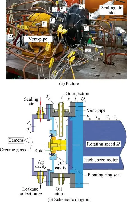
Fig. 2 Test section of high-speed sealing test rig.
2.2. Experimental method
The floating ring seal, including carbon ring, metallic sheath,wave spring, pressing plate, is indicated in Fig. 3. There is an eccentric clearance between the rotor and the carbon ring in stationary state. When the rotor begins to run, a fluid film arises in the clearance which becomes more and more uniform and concentric. To indicate the influence of sealing clearance,diameter and rotating speed, two different floating ring seals named High-speed Floating Ring Seal (HFRS) and Lowspeed Floating Ring Seal (LFRS) were investigated in both cold state and hot state in the study. HFRS is a seal with the inner diameter of 83.72 mm and maximum speed of 38,000 r/min, and LFRS is another seal with the inner diameter of 40.01 mm and maximum speed of 18,000 r/min.In order to outstand the advanced performance of floating ring seal,two different tests of labyrinth seals were also conducted.Here, a High-speed Labyrinth Seal (HLS) with the tip diameter of 83.61 mm and maximum rotating speed of 38,000 r/min was employed to accomplish the comparative analysis with HFRS.The width of HLS is 9.6 mm with 4 fins.The tip width is 0.3 mm and the height of the fin is 2.5 mm.Similarly,a Lowspeed Labyrinth Seal(LLS)with the tip diameter of 39.81 mm and maximum rotating speed of 18,000 r/min was used in the comparative tests with LFRS. The width of LLS is 6.8 mm with the fin number of 4. The tip width is 0.2 mm and the height of the fin is 2 mm.The initial sealing clearance between the labyrinth seal and the stator was set as that of the floating ring seal in cold state.In the stator,graphite coating was used to avoid the rubbing in rotating state. For comparison, the working parameters including rotating speed, pressure ratio and temperature were in conformance with those of the HFRS and LFRS.
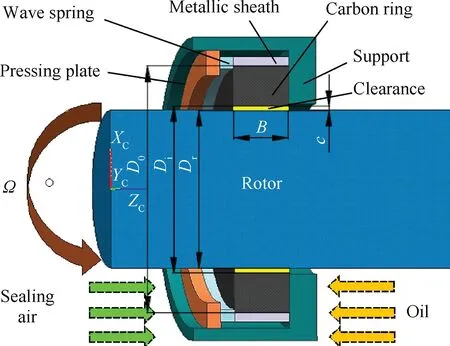
Fig. 3 Structure of floating ring seal.
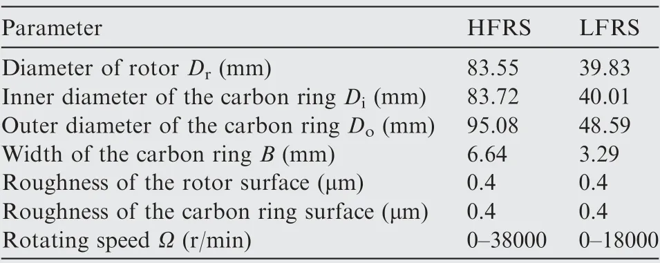
Table 1 Parameters of floating ring seals.
The test parameters were decided in terms of an aero-engine(Table 1). For the oil cavity, the flow rate of the oil injection(Jet oil II) varied from 1.2 L/min to 4.2 L/min to inspect the capacity of the floating ring seal. A turbo-flowmeter with the accuracy of ±0.5% was used to record the flow rate (Qo).For the air cavity, air injections with different pressure were performed to prevent the oil from fleeing. Six K-type armor thermocouples with the accuracy of ±0.4%t (t is the tested temperature) were set averagely in both air cavity and oil cavity.In cold state,the oil temperature and air temperature were both kept at 300 K.In hot state,the oil temperature was set to 343 K while it was as high as 371 K for the air.
The pressure ratio between air cavity and oil cavity varied from 1.0 to 2.0 during the test. Two pressure indicators with the accuracy of ±0.2% were connected to the oil cavity and the air cavity separately to measure the pressure ratio. Meanwhile, the leakage of oil ( ˙m), fleeing out of the oil cavity, converged to the bottom of the air cavity, which connected to a collector and the amount of the oil leakage was measured by an electric scale with the accuracy of 0.01 g (Fig. 1). No air escape could happen in the leakage collection. To make it more accurate, the leakage was collected for 10 minutes at any working condition.
In rotating state, the floating ring/rotor clearance can be treated as uniform and concentric. Therefore, the floating ring/rotor clearance (c) is defined as:

here, Diis the inner diameter of floating ring, mm; Dris the outer diameter of rotor, mm.
Table 2 lists the clearance in both hot state and cold state.In cold state, the inner diameter of floating ring and the outer diameter of rotor were measured by three-Coordinates Measuring Machine (CMM). Then, the floating ring/rotor clearance in cold state (cc) was achieved by Eq. (1). In hot state, the thermal expansion (γ) of rotor can be calculated as follows:

here,α is the expansion coefficient of the rotor.In the test,the rotor was made by 40CrNiMoA with the expansion coefficient of 12.8×10⁻⁶°C-1;This the temperature of hot state,K;Tcis the temperature of cold state, K.
The floating ring was made by carbon with the expansion coefficient of 1.2×10⁻⁶°C-1, which is far less than that of the rotor. Therefore, the expansion of the floating ring can be neglected. Then, the floating ring/rotor clearance in hot state (ch) can be given as follows:

Table 2 Distribution of sealing clearance.

A dimensionless definition of pressure ratio is defined as:

where,Pais the pressure of air cavity,Pa;Pmis the air-oil mixture in oil cavity, Pa.
Then,another definition of critical pressure ratio πcr,where the oil starts to leak into the air cavity, is applied to analyze leakage performance.The pressure ratio between the air cavity and the oil cavity is adjusted by a pin valve.An organic glass is placed in the wall of the air cavity. A camera is employed to record leaking conditions.
In the present study,Taylor number(Ta)is applied to measure the effect of rotation.The hydraulic diameter of the floating ring clearance (2c) represents the characteristic length and Ta is defined as:

here, umis the velocity of air-oil mixture and νmis the kinematic viscosity coefficient of air-oil mixture.
Leakage coefficient (φ) was firstly introduced in air sealing by Stocker et al.13, which indicates the relationship between leakage and working environment including pressure, temperature and sealing clearance as shown in Eq.(2). From this viewpoint, it is suitable for oil sealing on the condition that all characteristic parameters are selected according to oil (or oil-air mixture). Leakage coefficient(φ) is defined as:

where, A is the area between rotor and stator.
The measurement uncertainty of the leakage coefficient can be calculated by

The measurement uncertainty of the leakage coefficient can also be calculated by the same method and the maximum uncertainty for φ is ±1.5%.
3. Results and discussion
The leakage performance of the floating ring seal is indicated by the critical pressure ratio (πcr) and leakage coefficient (φ).Both HFRS and SLRS are investigated. The leakage performance is illustrated in detail to show the effects of pressure ratio, rotating speed and temperature (sealing clearance).Before the leakage discussion, vibration distributions occurring from 0 to 38,000 r/min for HFRS and from 0 to 18,000 r/min for LFRS were firstly considered.
3.1. Critical pressure
In this study,a critical pressure ratio is captured which can be initially used to measure the sealing capacity of the floating ring seals.
3.1.1. Distribution of critical pressure ratio in stationary state
Fig. 4 gives out the distributions of critical pressure ratio for both HFRS and LFRS in stationary state. The abscissa Qois the flow rate of the oil injection.The ordinate πcris the critical pressure ratio. As is shown, the critical pressure ratio increases with the rising of oil injection for both cold state and hot state. That is, larger oil injection needs more sealing air to prevent the oil from leakage.Comparing with the results in cold state,the critical pressure ratio at different oil injections are overall lower in hot state, which mainly attributes to the smaller sealing clearance as shown in Table 2. For HFRS,the maximum difference of critical pressure ratio between cold state and hot state is 0.33. However, it is only 0.07 for LFRS,which is greatly smaller than that of HFRS.As Table 2 shows,the difference of clearance between cold state and hot state is 0.038 mm for HFRS while it is just 0.018 mm for LFRS,which proves that the difference of the clearance directly decides the critical pressure ratio.
3.1.2. Distribution of critical pressure ratio in rotating state
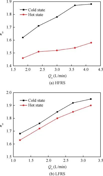
Fig. 4 Distribution of πcr in stationary state.
In this study, we mainly focus on the rotating performance of the floating ring seal especially in high rotating speed. Fig. 5 shows the distribution of critical pressure ratio (HFRS and LFRS). The abscissa Ta is the dimensionless Taylor number which is used to measure the effects of rotation.Fig.5(a)firstly shows the critical pressure ratio of HFRS. In accordance with the rule (in Section 3.1.1) in stationary state, the critical pressure ratio increases when oil injection increases from 1.8 L/min to 4.2 L/min. And, perhaps most impressively, the function of rotation in hot state is different from that in cold state. It is clearly shown that critical pressure ratio keeps consistent with the increase of Taylor number in cold state. However, critical pressure ratio drops dramatically in hot state as Taylor number is increased. The different performance of critical pressure ratio between hot state and cold state can attribute to the stability of fluid film (shown in Fig. 6) in the floating ring seal clearance, which forms in rotating state as is pointed out in Ref.6. The fluid film directly decides the sealing capacity of floating ring seal. In cold state, the initial floating ring seal clearance is as large as 0.085 mm (Table 2), which is too large to establish a stable fluid film.In hot state,the initial clearance reduces to 0.047 mm as the function of thermal expansion,which facilitates the formation of fluid film. With the increase of rotation, the fluid film becomes more and more compacted under the action of centrifugal force, which can prevent more oil from leaking.
Followed is the critical pressure ratio of LFRS given in Fig.5(b).Rotation has no effect on critical pressure ratio both in cold state and hot state, which is different from that of HFRS. From Table 1 we can see that the rotor diameter of LFRS is only 39.83 mm, which is far less than 83.55 mm, the rotor diameter of HFRS. Consequently, the rotor expansion of LFRS is relatively smaller.As is given in Table 2,the initial floating ring seal clearance is 0.090 mm in cold state while it is still 0.072 mm in hot state.Although the increasing centrifugal force could, to some extent, reduce the clearance with the rotating speed increase,the larger initial clearance still impedes the formulation of the fluid film so that the influence of the rotation is submerged. This further proves that it is hard to shape the stable fluid film when the floating ring seal clearance is relatively larger. In addition, the above phenomenon firstly addresses the relationship between the fluid film and the rotor diameter in hot state.

Fig. 5 Distribution of πcr in rotating state.
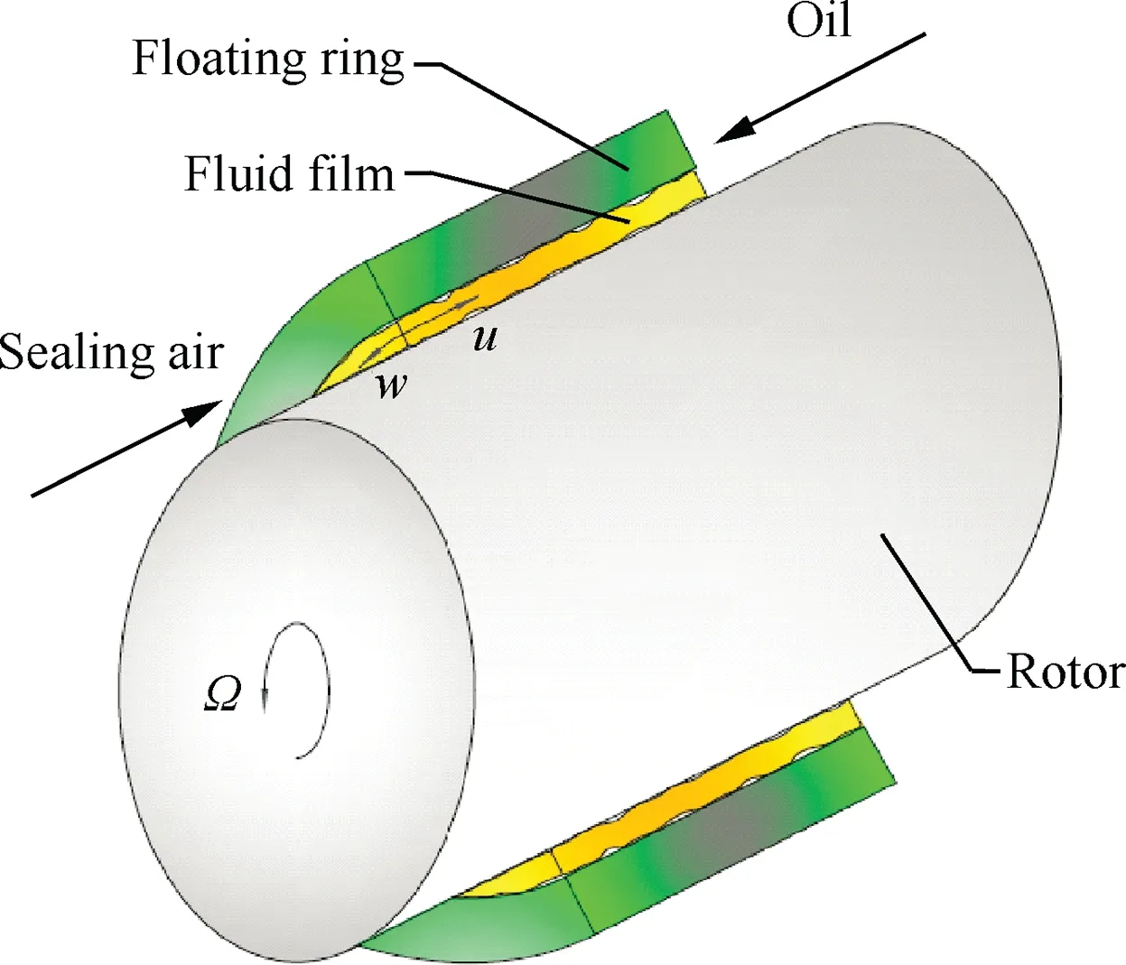
Fig. 6 Flow structure in sealing clearance.
3.2. Leakage zone
In the test we discover that there is a zone only where leakage change is captured. According to Section 3.1, leakage occurs when the pressure ratio is smaller than the critical pressure ratio. In this section, the distributions of leakage are mainly talked about below the critical pressure ratio. From Fig. 7 we can see that there is a leakage beginning line and a leakage consistent line. The leakage beginning line corresponds to all of the critical pressure ratios at different oil injections. As expected, there is no oil leakage if the pressure ratio exceeds the critical pressure ratio. On the other hand, when the pressure ratio keeps down, the leakage goes up and finally keeps consistent. Here, a leakage consistent line comes into view.The leakage zone, formed by the leakage beginning line and leakage consistent line, contains all the leakage change of the floating ring seal in the test.
Fig.7(a)gives out the leakage zone of HFRS.The ordinate ˙mis the mass flow rate of leakage. The oil injections including 1.8 L/min, 3.0 L/min and 4.2 L/min are investigated. At Qo=1.8 L/min, the leakage zone is very small. With the increase of oil injection, the leakage zone is enlarged. Fig. 7(b)plots the leakage zone of LFRS.It is obvious that the leakage zone is, more or less, larger than that of HFRS. Besides,the pressure ratios corresponding to the leakage zone of LFRS are larger than those of HFRS. The reasons for the above analysis can attribute to the different diameter and sealing clearance.
3.3. Leakage comparison between floating ring seal and labyrinth seal
The leakage analysis is performed at different oil injection,Taylor number and working temperature.In order to highlight the advantages of floating ring seal, comparisons between floating ring seals (HFRS and LFRS) and labyrinth seals(HLS and LLS from Ref.14) were conducted. The vibration from 0 to 38,000 r/min was monitored and the experimental repetition of the leakage was also conducted.
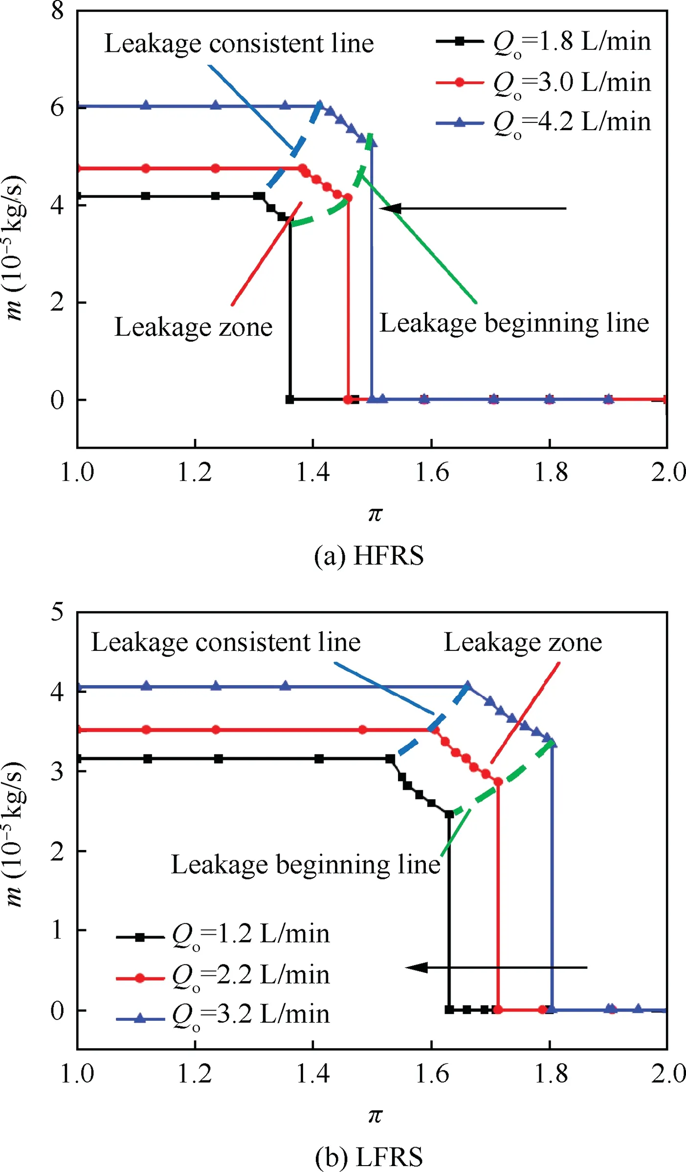
Fig. 7 Leakage zone.
3.3.1. Vibration and leakage repetition
Both the horizontal and vertical vibration values were recorded during all of the leakage tests. Fig. 8 gives out the vibration distribution in hot/cold state. The abscissa Ω is the rotating speed and the ordinate V is the vibration acceleration.As is plotted in Fig. 8(a), the rotating speed varies from 0 to 38000 r/min for HFRS. It is shown that there are two critical speeds at 8000 r/min and 13500 r/min where the vibration values are relatively larger. After that, the vibration is continuously stable. For LFRS, two critical speeds also have been shown in Fig. 8(b). The distributions of the critical speed are almost the same to those of HFRS.According to the vibration analysis,the rotor is able to avoid resonance vibration and the critical speed in the test.Therefore,the vibration nearly has no effect on the leakage.
From Fig. 2(b) we can see that the rotor-bearing system of the test is a typical cantilever structure.Therefore,the rotordynamic performance is mainly decided by the rotor structure of the high-speed motor. The temperature variation of the leakage flow in hot state almost has no effect on the high-speed motor so that the vibration magnitude is about the same under both states.
Fig. 9 shows the leakage repetition for both HFRS and LFRS. The abscissa Ω is the rotating speed and the ordinate ˙m is the leakage magnitude. The rotating speed changes from 0 to 38000 r/min for HFRS with the pressure ratio of 1.45 and oil injection of 3.0 L/min. Meanwhile, the rotating speed varies from 0 to 18000 r/min for LFRS with the pressure ratio of 1.68 and oil injection of 2.2 L/min. The definitions of cold state and hot state have been given in Section 2.2. From Fig. 9(a) we can see that the maximum error of the leakage magnitude in cold state,occurring at Ω=9000 r/min,is about 3.24%. In the same time, the maximum error in hot state is only 1.38% which happens at Ω=6000 r/min. Overall, the repeatability of HFRS is very well.
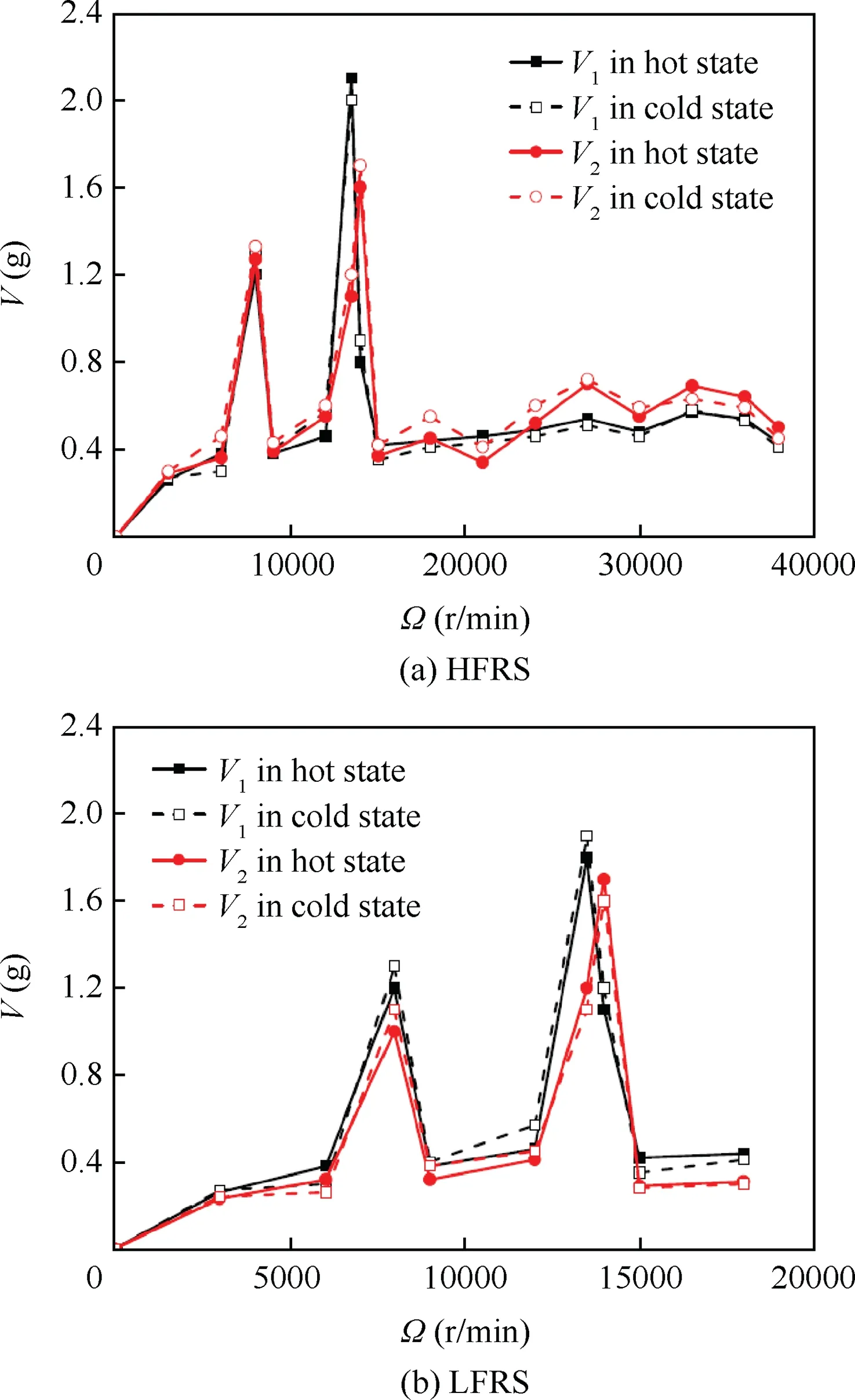
Fig. 8 Distribution of vibration.
Fig. 9(b) gives out the leakage repetition of LFRS. The rotating speed varies from 0 to 18000 r/min. In cold state,the maximum error appears at Ω=12000 r/min with a value of 0.45%. In hot state, the maximum error is 0.89% which is achieved at Ω=15000 r/min. Totally, good repeatability and accuracy for the leakage coefficient analysis are provided in both cold state and hot state.
3.3.2. Distribution of leakage coefficient in stationary state
Fig. 10 demonstrates the dependence of leakage coefficient upon oil injection in stationary state. The tests are done at two different temperatures. Fig. 10(a) compares the results of HFRS and HLS. It is shown that the leakage coefficient increases with the oil injection rising.
Firstly, the comparison of leakage coefficient between cold state and hot state is done for HFRS. At Qo=1.8 L/min,the leakage coefficient in cold state is 2.04×10⁻⁴K0.5s/m while it rises to 3.36×10⁻⁴K0.5s/m in hot state.Here,a difference of 1.32×10⁻⁴K0.5s/m is obtained.At Qo=4.2 L/min,the maximum value in the test, the leakage coefficient in cold state becomes 3.34×10⁻⁴K0.5s/m and it increases to 5.97×10⁻⁴K0.5s/m in hot state. Then, a larger difference of 2.63×10⁻⁴K0.5s/m is achieved. That is, the leakage coefficient in hot state is larger than that in cold state and the difference is enlarged with the increase of oil injection.

Fig. 9 Leakage repetition.
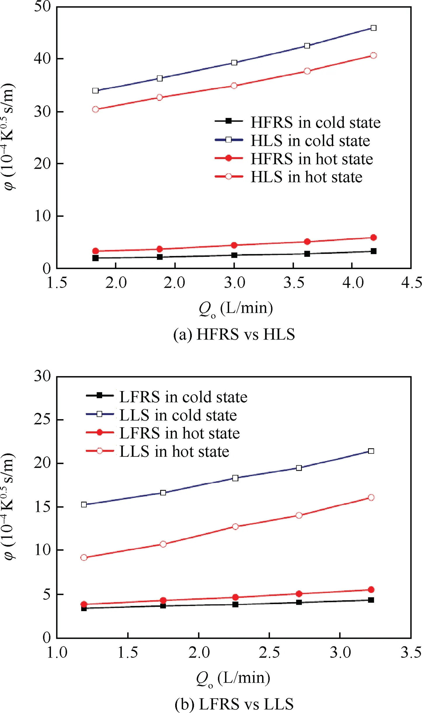
Fig. 10 Distribution of leakage coefficient in stationary state(comparing with labyrinth seal).
Secondly, the comparison of leakage coefficient between HFRS and HLS is carried out.In cold state, the leakage coefficient is 2.04×10⁻⁴K0.5s/m for HFRS while it sharply increases to 33.90×10⁻⁴K0.5s/m for HLS at Qo=1.8 L/min, which generates a difference of 31.86×10⁻⁴K0.5s/m between HFRS and HLS. When oil injection reaches 4.2 L/min, the difference is enlarged to 42.59×10⁻⁴K0.5s/m. In hot state, a similar rule is also presented. As a conclusion,the leakage coefficient of HFRS is overall greatly smaller than that of HLS.
For HLS, the leakage coefficient in hot state is, as anticipated, overall smaller than that in cold state. For HFRS, an attractive and converse phenomenon is that the leakage coefficient in hot state exceeds that in cold state. From Eq. (6) we can see that the leakage coefficient is a synthesis of leakage( ˙m),temperature(Tm),pressure(Pm)and sealing area between the rotor and floating ring (A). As shown in Table 2, a great decrease of sealing clearance is presented from cold state to hot state, which directly reduces the sealing area A. Although ˙m decreases from cold state to hot state, it still cannot offset the reduction of A so that the leakage coefficient increases from cold state to hot state. For HLS, the magnitude of ˙m far outstrips that of HFRS. Hence, with the same reduction of A to HFRS,the great decrease of ˙m generates smaller leakage coefficient from cold state to hot state for HLS.
Fig. 10(b)gives out the results of LFRS and LLS.The distributions are almost the same to those of HFRS and HLS.The typical distinction is that the difference between LFRS and LLS is not as large as that of HFRS and HLS, which mainly associates with the sealing clearance and diameter.
3.3.3. Distribution of leakage coefficient in rotating state
(1) Comparisons between stationary state and rotating state for both HFRS and HLS
From Fig. 10(a) we can see that the leakage coefficient increases with the oil injection in stationary state which, just as expected,can directly reflect the sealing capacity of floating ring seal for aero-engine in the period of start-up and shutdown. From Fig. 11(a) we find that the leakage coefficient decreases with the rotating speed which, further, inspects the sealing capacity of floating ring seal for aero-engine in different operating state.
For HFRS in cold state, the leakage coefficient is 2.60×10⁻⁴K0.5s/m (Fig. 10(a)) at Ta=0, and it decreases to 2.15×10⁻⁴K0.5s/m(Fig.11(a))at Ta=36.2.Herein,only a reduction of 0.45×10⁻⁴K0.5s/m is achieved. That is, the effect of rotation is not obvious in cold state. For HFRS in hot state, the leakage coefficient becomes 4.48×10⁻⁴K0.5s/m(Fig. 10(a)) at Ta=0, and it changes to 2.98×10⁻⁴K0.5s/m(Fig.11(a))at Ta=36.2,which provides an impressive reduction of 1.5×10⁻⁴K0.5s/m, almost 3 times that in cold state.In cold state, the larger sealing clearance slows down the formation of fluid film so that the reduction of leakage coefficient is very small. Here, a dimensionless ratio of sealing clearance to rotor diameter (2c/Dr) is employed to analyse the leakage performance. As Table 3 indicated, 2c/Dris 2.035×10⁻³in cold state and it drastically reduces to 1.125×100.5in hot state. Based on the reduction of 2c/Dr, the fluid film is enhanced so that the sealing capacity of floating ring seal is improved considerably.
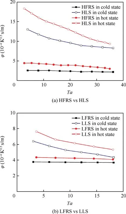
Fig. 11 Distribution of leakage coefficient in rotating state(comparing with labyrinth seal).
Continually it can be found that the leakage coefficient of HLS is overall larger than that of HFRS. For HLS in cold state, the leakage coefficient is 39.28×10⁻⁴K0.5s/m at Ta=0, and it reduces to 8.27×10⁻⁴K0.5s/m at Ta=36.2.Herein,a great reduction of 31.01×10⁻⁴K0.5s/m is obtained,which is 69 times that of HRFS. For HLS in hot state,the leakage coefficient firstly equals to 34.88×10⁻⁴K0.5s/m at Ta=0, and it decreases to 9.33×10⁻⁴K0.5s/m at Ta=36.2, which provides a reduction of 25.55×10⁻⁴K0.5s/m, 17 times that of HRFS. As described by Li et al.14, a blocking ring, generated by centrifugal force, plays an important role in oil sealing in rotating state so that the effect of rotation is more evident for labyrinth seal. A clear distinction is captured that the leakage coefficient of HLS in hot state is,in contrast to the stationary state,larger than that in cold state, which can mainly attribute to the sharp decrease of sealing area derived from clearance.
From the above analysis we can see that the leakage coefficient decreases from stationary state to rotating state,especially in hot state,for both floating ring seal and labyrinth seal.However,the decreasing extent for floating ring seal is far less than that of the labyrinth seal.
(2)Comparisons between stationary state and rotating state for both LFRS and LLS
Fig. 10(b) shows that more oil injection produces larger leakage coefficient for LFRS which agrees with the conclusion of HFRS.However,the influence of rotation can be neglected both in cold state and hot state. Fig. 11(b)further proves that increasing rotating speed can,more or less,reduces the leakage coefficient.However,the reduction is very small due to the larger 2c/Dras shown in Table 3.
For LFRS in cold state, the leakage coefficient is 3.79×10⁻⁴K0.5s/m at Ta=0, and it decreases to 3.69×10⁻⁴K0.5s/m at Ta=18.1. Hence, only a drop of 0.10×10⁻⁴K0.5s/m is gained. For LFRS in hot state, the leakage coefficient grows to 4.37×10⁻⁴K0.5s/m at Ta=0,and it reduces to 4.08×10⁻⁴K0.5s/m at Ta=18.1, which presents a change of 0.21×10⁻⁴K0.5s/m, essentially two times that in cold state.Comparing with HFRS,the reduction of leakage coefficient from Ta=0 to Ta=18.1 for LFRS is very small both in cold state and hot state, which is mainly in terms of 2c/Dr. As Table 3 indicated, 2c/Dris 4.519×10⁻³in cold state and it just reduces to 3.612×10⁻³in hot state, both of which are larger than those of HFRS.Although the rotor diameter of LFRS is smaller, the leakage coefficient is still over that of HFRS in the whole. Therefore,the sealing diameter does not bring substantial changes in leakage coefficient. Being a decisive parameter, the magnitude of 2c/Drdetermines the leakage coefficient.
For LLS in cold state, the leakage coefficient is 18.32×10⁻⁴K0.5s/m at Ta=0, and it reduces to 4.35×10⁻⁴K0.5s/m at Ta=18.1. Herein, a great reduction of 13.97×10⁻⁴K0.5s/m is obtained, which is 23.7 times that of LRFS. For LLS in hot state, the leakage coefficient firstlyis 12.72×10⁻⁴K0.5s/m at Ta=0, and it decreases to 5.34×10⁻⁴K0.5s/m at Ta=18.1,which provides a reduction of 7.38×10⁻⁴K0.5s/m, 6.3 times that of LRFS. Comparing with HLS and HFRS, although the leakage coefficient of LLS is still larger than that of the LFRS, the difference has been reduced by the enlarged 2c/Dr.

Table 3 Distribution of 2c/Dr.
The difference of leakage performance talked above mainly associates with the underlying mechanism of floating ring seal and labyrinth seal.For floating ring seal,the fluid film plays an important role in oil sealing. With the increase of rotating speed, the fluid film becomes more and more stable in terms of suitable 2c/Dr. For labyrinth seal, although the penetration of oil is reduced when the sealing clearance decreases from cold state to hot state, the overall sealing capacity is still relatively weaker than floating ring seal.
In depth, the flow velocity distribution in the sealing clearance of floating ring seal may serve as an explanation for the sealing performance. As plotted in Fig. 6, an axial velocity(u) is generated by pressure ratio and a frame velocity (w) is induced by rotation. The frame velocity has a blocking influence on the flow across the clearance, which can reduce the leakage.With the increasing of the rotating speed,the enlarged frame velocity decreases the oil leakage.
The stability of the fluid film in the sealing clearance, mentioned in Section 3.1.2, is decided by both the axial velocity and the frame velocity.The blocking effect of the frame velocity is enhanced by the increasing of the rotating speed. For HFRS,the frame velocity plays the leading role in the hot state with a suitable 2c/Dr. However, the axial velocity dominates the flow in the cold state with a larger clearance so that the effects of rotation is not obvious.The same cases occur in both cold and hot state for SLRS because 2c/Dris too large to establish stable fluid film.
4. Conclusions
The floating ring seal was used for oil sealing in bearing chamber of the aero-engine. Measurements in cold/hot state were conducted to investigate the leakage performance of HFRS and SLRS in High-speed Sealing Test Rig.The effects of rotating speed, clearance and pressure ratio were analyzed. Comparisons between floating ring seal and labyrinth seal were performed and several conclusions could be drawn from the above analysis:
A critical pressure ratio exists where leakage begins to come into view.The critical pressure ratio in cold state is larger than that in hot state. For HFRS, the critical pressure ratio decreases with the increase of Taylor number in hot state.For LFRS, the critical pressure ratio keeps almost consistent when Taylor number varies from 0 to 18.2 in both cold state and hot state.
There is a zone where leakage variation is captured. Leakage appears from the leakage beginning line and keeps consistent after the leakage consistent line. The leakage zone of LFRS is, to some extent, larger than that of HFRS.
The dimensionless parameter 2c/Drplays an important role in fluid film which appears in the sealing clearance and directly decides the leakage performance of the floating ring seal in cold/hot state. At 2c/Dr=1.125×10-3, the most stable fluid film forms so that the leakage performance is greatly improved.
In stationary state, higher leakage coefficient is achieved in hot state for floating ring seal while it is in cold state for labyrinth seal. In rotating state, higher leakage coefficient is obtained in hot state for both floating ring seal and labyrinth seal. Comparing with labyrinth seal, the influence of Taylor number is relatively smaller on floating ring seal. Overall, the leakage performance of the floating ring seal behaves better than labyrinth seal. The typical feature of floating ring seal is highlighted from the above comparison.
The present paper firstly provides experimental data on floating ring seal for oil sealing, which is sure as hell need for aero-engine.Follow,the researchers and designers can take some of the results into account in seal design.
Acknowledgments
This work was supported by the National Natural Science Foundation of China (Nos. 51706223 and 51576193).
杂志排行
CHINESE JOURNAL OF AERONAUTICS的其它文章
- Heading control strategy assessment for coaxial compound helicopters
- An adaptive integration surface for predicting transonic rotor noise in hovering and forward flights
- An algorithm to separate wind tunnel background noise from turbulent boundary layer excitation
- Simulation of mass and heat transfer in liquid hydrogen tanks during pressurizing
- Six sigma robust design optimization for thermal protection system of hypersonic vehicles based on successive response surface method
- An active damping vibration control system for wind tunnel models
