Ride quality evaluation of the soil compactor cab supplemented by auxiliary hydraulic mounts via simulation and experiment
2019-10-15NguyenVanLiemZhangJianrunHuaWenlinWangPeiling
Nguyen Van Liem Zhang Jianrun Hua Wenlin Wang Peiling
(1School of Mechanical Engineering, Southeast University, Nanjing 211189, China)(2School of Mechanical and Electrical Engineering, Hubei Polytechnic University, Huangshi 435003, China)
Abstract:In order to evaluate the ride quality of the soil compactor cab supplemented by the auxiliary hydraulic mounts (AHM), a nonlinear dynamic model of the soil compactor interacting with the off-road deformable terrain is established based on Matlab/Simulink sofware. The power spectral density (PSD) and the weighted root mean square (RMS) of acceleration responses of the vertical driver’s seat, the cab’s pitch and roll angle are chosen as objective functions in low-frequency range. Experimental investigation is also used to verify the accuracy of the model. The influence of the damping coefficients of the AHM on the cab’s ride quality is analyzed, and damping coefficients are then optimized via a genetic algorithm program. The research results show that the cab’s rubber mounts added by the AHM clearly improve the ride quality under various operating conditions. Particularly, with the optimal damping coefficients of the front-end mounts ca1,2 = 1 500 N·s/m and of the rear-end mounts ca3,4 =2 335 N·s/m, the weighted RMS values of the driver’s seat, the cab’s pitch and roll angle are reduced by 22.2%, 18.8%, 58.7%, respectively. Under the condition of the vehicle travelling, with the optimal damping coefficients of ca1,2 = 1 500 N·s/m and ca3,4 =1 882 N·s/m, the maximum PSD values of the driver’s seat, the cab’s pitch and roll angle are clearly decreased by 36.7%, 54.7% and 50.6% under the condition of the vehicle working.
Key words:off-road soil compactor; dynamic model; cab’s rubber mounts; auxiliary hydraulic mount; ride quality
The soil compactor often works in the field of the construction site, factories, etc. Its operating principle is a combination of the static force of the vehicle and the dynamic force of the drum to compact the soil ground, asphalt and other materials. The vibration excitations from the deformable terrain and drum are thus transmitted to the driver through the isolation systems of the cab and the vehicle. Consequently, the cab’s isolation system is one of the most important factors to improve the vehicle ride quality.
The basic research of the tire-deformable terrain contact[1-4]and interaction between the rigid drum and elastic-plastic soil[5]indicated that the vibration response of the vehicle was greatly influenced by off-road terrains. Almost all the cab’s isolation system of soil compactors was equipped by the rubber mounts with high stiffness characteristic and low damping of rubber material[6-9]. Therefore, the stiff rubber property helped suppress only high-frequency vibrations and noise, contrariwise, the low damping of the natural rubber generated the high magnitude vibrations which can reduce the vehicle’s ride quality[6]. The effects of design parameters of the cab’s rubber mounts on the ride quality was evaluated[7]. An optimal design for the cab’s new rubber mounts of soil compactors was built via the finite element model, and the new rubber mount was then produced and tested for the vehicle’s cab[8]. The parameters of the cab’s rubber mounts were also optimized to increase the ride quality[9]. The results showed that the vehicle’s ride quality was significantly improved. However, the research results also showed that the large-amplitude shock of the cab existed in the low-frequency region at the direction of forwarding motion. This is one of the reasons that causes the tiredness of the driver while working, cracking surfaces of the cab and other problems. Thus, to solve this problem, the low damping coefficients of the cab’s rubber mounts need to be improved.
In this study, a 3-D dynamic model of the soil compactor was established based on the deformable terrain models[1,4-5]. The vibration excitations consist of the drum/tires-deformable terrain contact under the condition of the vehicle traveling and an excitation (28 Hz) of the drum under the condition of the vehicle working on elastic-plastic soil. Experimental investigation was used to validate the model and verify its accuracy. The cab’s rubber mounts were supplemented by auxiliary hydraulic mounts (AHM) to evaluate the ride quality, and the damping coefficients of the AHM were then optimized by the genetic algorithm to enhance the vehicle’s ride quality. The performance of AHM was evaluated through the weighted RMS and the PSD of acceleration responses of the vertical driver’s seat, the cab’s pitch and roll angle in the low-frequency region. The aim of this study is to improve the ride quality and control the cab shaking.
1 Soil Compactor Model
1.1 Vehicle dynamic model
A 3-D nonlinear dynamic model of the vehicle with 9 degrees of freedom (DOF) considering the interaction between wheels and off-road terrains is established to evaluate the cab’s ride quality (see Fig.1).

(a)

(b)
As shown in Fig.1,zvandmvare the vertical displacement and mass at the centre of gravity of the driver’s seat, the cab, the rear/front vehicle frame and the drum;φ2andφ3are the pitch angles at the centre of gravity of the cab and the rear frame;θjis the roll angle at the centre of gravity of the cab, the rear/front frame and the drum;ks,kd1,2,kt1,2andcs,cd1,2,ct1,2are the stiffness and damping coefficients of the driver’s seat suspension, the drum’s rubber mounts and tires, respectively ;Fciare the dynamic reaction forces of the cab’s isolation mounts;qd1,2andqt1,2are the excitations of the off-road terrains;luandbvare the distances of the vehicle (i=1, 2,3,4;j=2,3,4,5;u=1,2,…, 8;v=1,2,…,5).
Based on the vehicle dynamic model in Fig.1, and by applying Newton’s second law of motion, the motion equations of the soil compactor can be represented in the matrix form as

(1)
whereM,CandKare the mass, damping and stiffness matrices, respectively;Zis the displacement vector; andF(t) is the exciting force vector.
1.2 Cab’s isolation system model
The cab’s isolation system of the soil compactor was equipped by four rubber mounts to isolate the transmittal vibration sources from the rear vehicle frame to the cab floor. Due to the low performance of the old rubber mount in improving the ride quality, especially the high pitch angle of the cab, a new optimal design of the cab’s rubber mounts was then carried out to improve the cab’s ride quality[8]. However, its vibration isolation performance is still small in the low-frequency region.

Fig.2 Cab’s isolation system model
In this study, a new rubber mount supplemented by the AHM is proposed to further improve the cab’s ride quality. The lumped parameter model is shown in Fig.2, wherekrandcrare the stiffness and damping coefficient of the new rubber mount, respectively;cais the damping coefficient of the AHM added in the cab’s rubber mounts.
The corresponding dynamic force of mountiof the cab’s isolation system is given as
(2)

(3)

(4)
wherei=1, 2, thenα= 1,v=5 andδ=i+1; andi=3, 4, then=2,v=4 andδ=i-1.
1.3 Vehicle and terrain interaction models
1.3.1 Wheels-deformable soil contact
Under the condition of the vehicle travelling, the drum/tires are assumed to move on a deformable terrain with the terrain surface roughness. Based on the model of Bakker and Wong[1-2], when a wheel moves on a random terrain surfaceq(t) of the deformable terrain, under the effect of the static and dynamic loads of the wheel, the terrain is then sunk byzoa, as shown in Fig.3. The pressurepgand the shear stressτgarising from the soil compression in the deformable region (arc ofoa) thus impact on the wheel. Thus, the reaction forceFgof the terrain under the wheel is given as

(5)
pgandτgare given by Bakker[1]as follows:
(6)
wherekcandkφare the soil stiffness coefficients for sinkage and internal friction, respectively;nis the sinkage exponent;bis the smaller dimension of the contact patches and the widths of the drum/tireB;ris the radius of the drum/tire;cis the soil cohesion coefficient;φis the angle of the internal friction;Kis the shear deformation modulus; andj=rs[θa(t)-θ] in whichsis the slip ratio of the drum/tire.

Fig.3 Wheel-deformable terrain contact model
Assume thatlaris the average roughness line of the terrain surface, and thus, the sinking of the terrainzxcan be determined byzx=q(t)+zoa-, herein,q(t) is the random excitation of the off-road terrain surface and it is described as follows.
According to the ISO proposal[10], the spectral density of the off-road terrain surface is written as
(7)
The valueS(Ω0) provides a measure for the random terrain with the reference spatial frequencyΩ0= 1/(2π) cycle/m. More specifically, assuming that the vehicle moves with a constant speedv0, the off-road terrain irregularities can then be simulated by
(8)
whereNis the number of intervals;φiis a random phase uniformly distributed between 0 and 2π; andω=nv0is the fundamental temporal frequency.
The desired terrain roughness can be yielded by choosing a value in the spectral density ranges.
According to the vehicle dynamic model in Fig.1 and the wheels-deformable soil contact model in Fig.3, the excitation forcesFtandFdof the drum and tires are described by
(9)

(10)
1.3.2 Drum and elastic-plastic soil interaction
The soil compactor uses the most of its time to work on the elastic-plastic soil. Therefore,according to Adam and Kop[5], a model of the rigid drum and elastic-plastic soil interaction is established in Fig.4. The elastic-plastic property of soil can be expressed via a plasticity factorεand a damping ratio of plastic soilγas
(11)
whereεis the compression ratio;kseis the elastic stiffness;kspis the compression stiffness;cseis the compression damper.

Fig.4 Rigid drum and elastic-plastic soil interaction model
In a vibration cycle of the drum-soil interaction,there are two or three distinct phases that occur in the motion of the drum and they are described as follows:
1) Loading phase: The gravel-soil ground is compressed by the drum, thus, the density is increased and it has become elastic. The elastic stiffness and compression stiffness of the gravel-soil ground are increased while the compression damper is decreased. In order to describe the relation ofz5,εandγ, the vibration equation of the drum is given as[7]
(12)
2) Unloading phase: The drum moves upward, and the gravel-soil ground is restored. The vibration equation of the drum is written as
(13)
3) Drum-Hope phase: The gravel-soil ground has become elastic, the drum is easy to separate from the soil ground surface, and the vibration equation is written as
(14)
From Eqs.(12) to (14), the motion of drumz5and excitation forceFdis then determined.
2 Experimental Model
2.1 Evaluating criteria
The ride quality is mainly evaluated via the weighted RMS acceleration response. In addition, according to ISO 2631-1[11], the PSD acceleration response are also applied to estimate the effect of vibration on the endurance limit of the human body. It is suggested that a low-frequency range below 10 Hz seriously affected the driver’s health and safety. In this study, the ride quality of the cab’s isolation system is evaluated via the PSD and the weighted RMS of acceleration responses of the vertical driver’s seat, cab’s pitch and roll angle in the frequency and time domains. Thus, the smaller PSD and weighted RMS values mean that the system has the better ability compared to the corresponding isolation mounts. The expression of the weighted RMS value is given as
(15)
whereawtis the acceleration (translational and rotational) depending on the duration of the simulationT.
2.2 Experiment model
In order to confirm the model’s accuracy, an experimental condition of the soil compactor using the cab’s new rubber mounts was made under the same simulated condition when the vehicle worked on an elastic-plastic soil ground. Three test steps are described as follows:
Sept1Preparation step: Instruments for the experiment include a soil compactor, the Belgium LMS dynamic test and the analysis system; and ICP©three-direction acceleration sensors are used to measure the vibration accelerations. The sensors are installed on the driver’s seat and the cab floor at the four locations of the isolation mounts, as shown in Fig.5.
Sept2Measurement step: The multi-point measurement method is applied, and the process of measurement is performed under an excitation frequency 28 Hz of the drum when the vehicle compacted at a very slow speedv0= 0.83 m/s.
Sept3Data extraction step: The data measurements are carried out including the vertical accelerations at the driver’s seat and at four measurement points on the cab floor.
The acceleration responses of cab’s pitch and roll angle

Fig.5 Diagrammatic sketch of the experimental set-up
are calculated as
(16)
Experimental and simulation results of the PSD and weighted RMS of acceleration responses are plotted in Fig.6 and listed in Tab.1. The comparison results indicate that the simulation results almost agree with the tests regarding the frequency of the various peaks in the responses and the trend. In addition, the weighted RMS values of the vertical driver’s seat, cab’s pitch and roll angles also have a small deviation of 10.1%, 11.3% and 12.6% in comparison with the measured values. It implies that the mathematical model of the vibratory roller is an accurate and feasible model.

(a)

(b)

(c)

Tab.1 Comparison results of experiment and simulation
3 Results and Discussion
3.1 Influence of auxiliary hydraulic mounts
3.1.1 Under the condition of the vehicle travelling
In order to evaluate the influence of the damping coefficients of the AHM on the cab’s ride quality under the condition of the vehicle traveling, the parameters of the vehicle[6]and a Grenville soil deformation with its poor terrain classificationq(t)[3-4]are chosen to simulate at a low vehicle velocityv0=1.67 m/s. Assume that the initial damping coefficients of the AHM arec0=1.5103N·s/m. The damping coefficients of AHMcai=0.2c0, 0.4c0,…, 2.0c0in three different cases of the front-end mountsca1,2, the rear-end mountsca3,4and all mountsca1,2,3,4are respectively simulated. The results are shown in Fig.7.

(a)
(b)

(c)
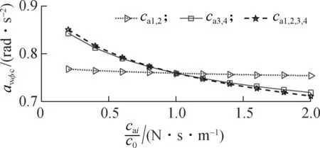
Fig.7 shows that the weighted RMS acceleration responses of the driver’s seat heaveawzs, the cab’s pitch and roll angle (awφcandawθc) are slightly affected by the damping coefficients of the front-end mountsca1,2, whereas these values are strongly affected by the damping coefficients of the rear-end mountsca3,4and of all mountsca1,2,3,4. However, the influence ofca1,2,3,4on the ride quality is insignificant in comparison withca3,4, thus,ca3,4are chosen to analyze the results. When 0.2c0≤ca3,4≤1.6c0, the results show that all values ofawzs,awφcandawθcare strongly reduced; when 1.6c0≤ca3,4<2.0c0, all values ofawzs,awφcandawθcare lightly reduced, especially the value ofawzsis tendentiously enhanced by 1.8c0≤ca3,4≤2.0c0, as shown in Fig.7(a). Thus, the cab’s ride quality can be greatly improved whenca1,2=1.0c0and 1.2c0≤ca3,4≤1.6c0.
3.1.2 Under the condition of the vehicle working
Under the condition of the soil compactor working on the workshop,an elastic-plastic soil ground with a high density soil[5]and a very slow-speed vehicle (v0=0.68 m/s) are chosen to simulate under an excitation (28 Hz) of the drum. Also, assume that the initial damping coefficients of AHM arec0=1.5103N·s/m. The damping coefficientscai=0.2c0, 0.4c0,…, 2.0c0with three different cases ofca1,2,ca3,4, andca1,2,3,4, are also evaluated, respectively.
The simulation results in Fig.8 show that the impact of the damping coefficientsca1,2,ca3,4, andca1,2,3,4is similar under the condition of the vehicle traveling. Consequently, the damping coefficients of the rear-end mounts,ca3,4, are also chosen to analyze the results. Figs.8(a),

(a)

(b)

(c)
(b) and (c) show that when 0.2c0≤ca3,4<1.4c0, all the values ofawzs,awφcandawθcare clearly reduced; however, when 1.4c0≤ca3,4≤2.0c0, the valueawφcis significantly enhanced (see Fig.8(b)). Therefore, the cab’s ride quality can be clearly improved whenca1,2=1.0c0and 1.0c0≤ca3,4≤1.4c0.
3.2 Performance of the AHM
The analysis results show that the ride quality is insignificantly affected byca1,2, whereas it is strongly affected byca3,4. The results also show that the ride quality is greatly improved when 1.2c0≤ca3,4≤1.6c0under the condition of the vehicle traveling and 1.0c0≤ca3,4≤1.4c0under the condition of the vehicle working. In order to choose the optimal values of the damping coefficients, a genetic algorithm program is used to optimize the objective functions.
3.2.1 Genetic algorithm program
The GA is defined as finding a vector variable through constraint conditions to reach the objective function[12-13], and it is written as
Finding a vectorx=[x1,x2,…,xn]Tto optimize
F(x)=[f1(x),f2(x),…,fn(x)]T
(17)
s.t.gi(x) ≤0i=1, 2,…,p
hj(x) = 0j=1, 2,…,q
whereF(x) is the objective function which must be either maximized or minimized;pandqare the numbers of inequality constraints and equality constraints.
The structure of GA includes encoding, population initialization, fitness evaluation, parent selection, genetic operations and termination criterion.
The goal of the GA is to seek the optimal damping coefficientsca3,4to obtain the minimumawzvalues in Eq.(15) via the subsystem model in two cases of the vehicle traveling and working. In order to find the minimumawzvalues, the fitness valueJis applied to calculate objective functions as[13-14]
(18)
s.t.
(19)
whereαzis the weight coefficient ofawzvalues;ca3,4are the damping coefficients of the AHM at the rear-end mounts, and the initial value ofca3,4for GA under the condition of the vehicle traveling is 1.8×10³≤ca3,4≤2.4×10³N·s/m and under the condition of the vehicle working is 1.5103≤ca3,4≤2.1103N·s/m.
The individuals with the higher fitness valueJwhich is obtained via the simulation model show that the obtained damping coefficientsca3,4are good. Therefore, the resultant individuals are updated before the evolution process ends, and the optimal individuals can be obtained.
In order to seek the optimal values ofca3,4in the cases of the vehicle traveling and working, the weight coefficientαzrespectively areαzs=0.548,αφc=0.366 andαθc=0.086, which are determined by the percent ofawzs(54.8%),awφc(36.6%) andawθc(8.6%) with the cab’s rubber mounts without AHM in Tab.2. The maximum generation is 600.
Tab.2 Weighted RMS values on a soft soil ground
The optimal result in Fig.9 shows all the fitness valuesJobtained in the case of the vehicle traveling. The maximum valuesJare not increased from the evolutionary generation of 462 to the end. Therefore, the optimal individuals can be obtained at the generation of 462, and the optimal value sought via GA isca3,4= 2 335 N·s/m. Similarly, the optimal value under the condition of the vehicle working isca3,4= 1 882 N·s/m.

Fig.9 Fitness results of the optimal running process
3.2.2 Performance on the deformable terrain
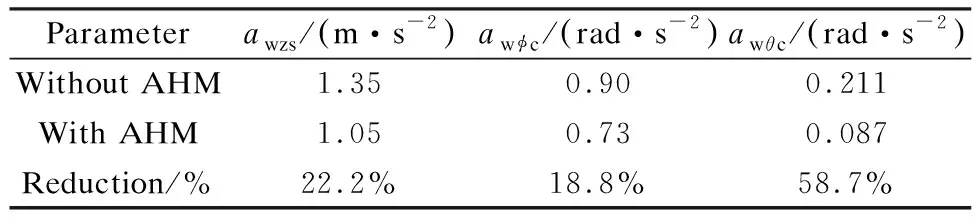
With the optimal damping coefficients ofca1,2=1 500 andca3,4=2 335 N·s/m, the weighted RMS and PSD of acceleration responses under the condition of the vehicle travelling are listed in Tab.2 and shown in Fig.10. The results in Tab.2 show that the values ofawzs,awφcandawθcare clearly decreased by 22.2%, 18.8% and 58.7% in comparison with the cab’s rubber mounts without AHM.
In addition, the results in Figs.10(a), (b) and (c) also show that the AHM added in the cab’s isolation system have almost no effect on the resonance frequencies of the rubber mounts. In addition, the maximum PSD values of the driver’s seat heave, cab’s pitch and roll angles are strongly reduced by 35.4%, 33.5 6% and 48.3% in the low-frequency region (below 10 Hz). Thus, the driver’s ride comfort and health are clearly improved by the AHM.
3.2.3 Performance on the elastic-plastic soil
With the optimal damping coefficients ofca1,2=1 500 andca3,4=1 882 N·s/m, the weighted RMS and PSD of acceleration responses under the condition of the vehicle working are also given in Tab.3 and Fig.11. The results in Tab.3 also show that the values ofawzs,awφcandawθcare reduced by 18.3%, 46.1% and 58.8% in comparison with the cab’s rubber mounts without AHM.

(a)

(b)

(c)

(a)

(b)

(c)
Besides, the results in Figs.11(a), (b) and (c) also show that the AHM have no effect on the resonance frequencies of the rubber mounts, and the maximum PSD values of the driver’s seat heave, cab’s pitch and roll angles are clearly decreased by 36.7%, 54.7% and 50.6% in the low-frequency region (below 10 Hz). Consequently, the driver’s ride comfort and health are also enhanced by the AHM under the condition of the vehicle working.

Tab.3 Weighted RMS values on an elastic-plastic soil ground
4 Conclusions
1) The driver’s ride comfort is strongly affected by the damping coefficientsca3,4of the AHM under the operation conditions of the vehicle.
2) With optimal damping coefficientsca1,2=1 500 andca3,4=2 335 N·s/m, the weighted RMS acceleration responses of the driver’s seat, the cab’s pitch and roll angle are clearly reduced by 22.2%, 18.8%, 58.7% under the condition of the vehicle travelling.
3) With optimal damping coefficientsca1,2=1 500 andca3,4=1 882 N·s/m, the maximum PSD acceleration responses of the driver’s seat, the cab’s pitch and roll angle are greatly decreased by 36.7%, 54.7% and 50.6% under the condition of the vehicle working. Therefore, the vehicle’s ride quality is significantly improved by auxiliary hydraulic mounts.
杂志排行

Journal of Southeast University(English Edition)的其它文章
- Tensile behaviors of ecological high ductility cementitious composites exposed to interactive freeze-thaw-carbonation and single carbonation
- Delay-performance optimization resource scheduling in many-to-one multi-server cellular edge computing systems
- Image denoising method with tree-structured group sparse modeling of wavelet coefficients
- Travel time prediction model of freewaybased on gradient boosting decision tree
- Projection pursuit model of vehicle emission on air pollution at intersections based on the improved bat algorithm
- Experimental investigation of oil particles filtration on carbon nanotubes composite filter