Structural mechanism and construction method of mud andwater inrush in Xiangyun tunnel of Guangtong-Dali railway
2019-09-18WANGYawei
WANG Yawei
Faculty of Geosciences and Environmental Engineering, Southwest Jiaotong University, Chengdu 611756, China
Abstract: Mud and water inrush in tunnel is a common problem in the construction process. Nowadays, the research and classification on this are mostly focused on karst situations. According to the characteristics of the surrounding rock and damage forms of the tunnel in the studied area, the author analyzed the geological and structural characteristics of mud and water inrush in tunnel and obtained their construction type. Meanwhile, the advanced water detection under the complex geological conditions was studied by using induced polarization method, transient electromagnetic method and three-dimensional seismic method, it can be concluded that the water-rich fracture zone exists within the detection range with a risk of large mud and water inrush disaster. The concrete construction treatment measures are put forward: ①cement-water glass binary slurry is selected as the material for ground and hole grouting, its advantage is that the gel time can be controlled, and it has certain grout ability in the strata with large permeability coeffcient, which is conducive to excavate construction immediately after grouting. ②applying the mature retrograde grouting construction can reduce grouting time and improve the excavation efficiency.
Keywords: mud and water inrush; geological model; Xiangyun tunnel; Guangtong-Dali railway; structural mechanism; construction method
0 Introduction
The mud and water inrush in the tunnel is a common problem in the construction process. It is influenced by geological structure and hydrogeological conditions, many researches have been carried out on classification of mud and water inrush at home and abroad with different emphasis. For example, Liuetal. (2017) classified the water storage structure; Linetal. (2008) divided the karst tunnel according to water form; Li (2009) distinguished the types of water inrush type according to the capacity of water in rush, forms of water inrush, anti-rush structure and disaster consequences; Mengetal. (2003) divided the water inrush of karst tunnels according to geological conditions; Wangetal. (2001) summarized the karst water inrush models; Wangetal.(2006), Luo (2014) classified the geological model of water inrush in karst tunnel according to the spatial distribution relationship between the tunnel and the karst pipeline; Zuoetal. (2001) classified the mud and water inrush from the tunnel according to the rush water source of the tunnel and the water storage structure of the groundwater.
It can be seen from above, the classification of mud and water inrush is mainly concentrated on karst environment (Heetal., 2001, 2005), but there is no systematic classification study on the influence of different types of geological characteristics on mud and water inrush disaster in areas where the fracture zones are developed. Therefore, Xiangyun tunnel crossing Xiangyun nappe structure is selected as the research object, considering its structure belt position, the geological model of the mud and water inrush is analyzed, combined with different advance prediction results, the concrete treatment measures are finally put forward.
1 Geological situation of the studied area
1.1 Geological conditions in the studied area
There developed faults in the studied area, of which Jinshajiang-Honghe fault plays an important role in the formation of the nappe structure (Fig.1a). The hidden faults in the Midu Basin (F3-F4) and the Xiangyun fault (F8) are parallel to the Honghe fault (F2), forming the east-west boundary limit faults of the Xiangyun nappe structure (Fig.1b). The Xiangyun nappe structure is generally distributed in the NW-SE direction (Fig.1), and reverse faults are generally developed in direction of NE-SW, all tend to the northwest. In order to fully reflect the distribution of thrust faults in Xiangyun nappe structure, two profiles were established parallel and perpendicular to the Xiangyun nappe structure(Fig.2).
The tunnel construction is affected by Chaoyangcun fault and Shangbeiyi fault, and the two faults are located in the exit area where mud and water inrush happened. The two faults are described as below:
(1)Chaoyangcun fault: the reverse fault is tens of kilometers long, with an attitude of N63° E/70°NW, the fault bandwidth of 30--150 m, the fault angle of 40° with the line, the footwall consists of Permian basalt, and the hangingwall is made up of Carboniferous thick limestone, with attitude of N25°--35°/71°--88°NW, with broken rocks, well-developed joints and aboundant groundwater.
(2) Shangbeiyi fault: the normal fault is approximately N-S trending, with attitude of N20°S/70°W, the fault bandwidth is 30--100 m and the angle with the line at 79°, and the footwall consists of Mid-Upper Carboniferous limestone, whereas the hanging wall consists of Lower Devonian Lianhuaqu Formation limestone, marl shale, sandstone, with joints developed.
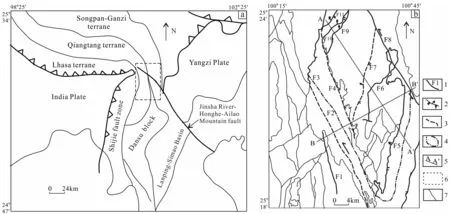
1-Fault; 2-reverse fault; 3-blind fault; 4-nappe area; 5-profile line; 6-the studied area;7-secondary fracture. Fig.1 Tectonic geological map for the studied area (a) and Xiangyun nappe structure sketch (b) (Niu et al., 2017)
2 Mechanism of mud and water inrush in tunnel
2.1 Overview of mud and water inrush in Xiangyun Tunnel
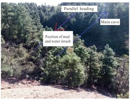
Fig.3 Position of Xiangyun tunnel
The Lower Permian strip-shaped limestone of the tunnel outlet section develops a large deep spring at about 3 km on the left side of the line (the elevation is about 1 940 m), the flow rate can reach 21.73 L/s, the parallel adit of the tunnel is located on the right side of the line, and the spacing between the main side walls is less than 20 m (Fig.3).
After the excavation of the tunnel to the section of D1K146+080.8--080.2, the rock of the tunnel face and its left and right low parts of arch are gray black carbonaceous shale, mudstone and marlite, mixed with a small amount of red brown broken stone. There are many scattered water flows above the vault with a small amount of dripping and multiple strands of water flowing out of the arch, where mud and water inrush occurred many times, and the amount of water continued to increase, which was discharged to the low side of the line (Fig.4).
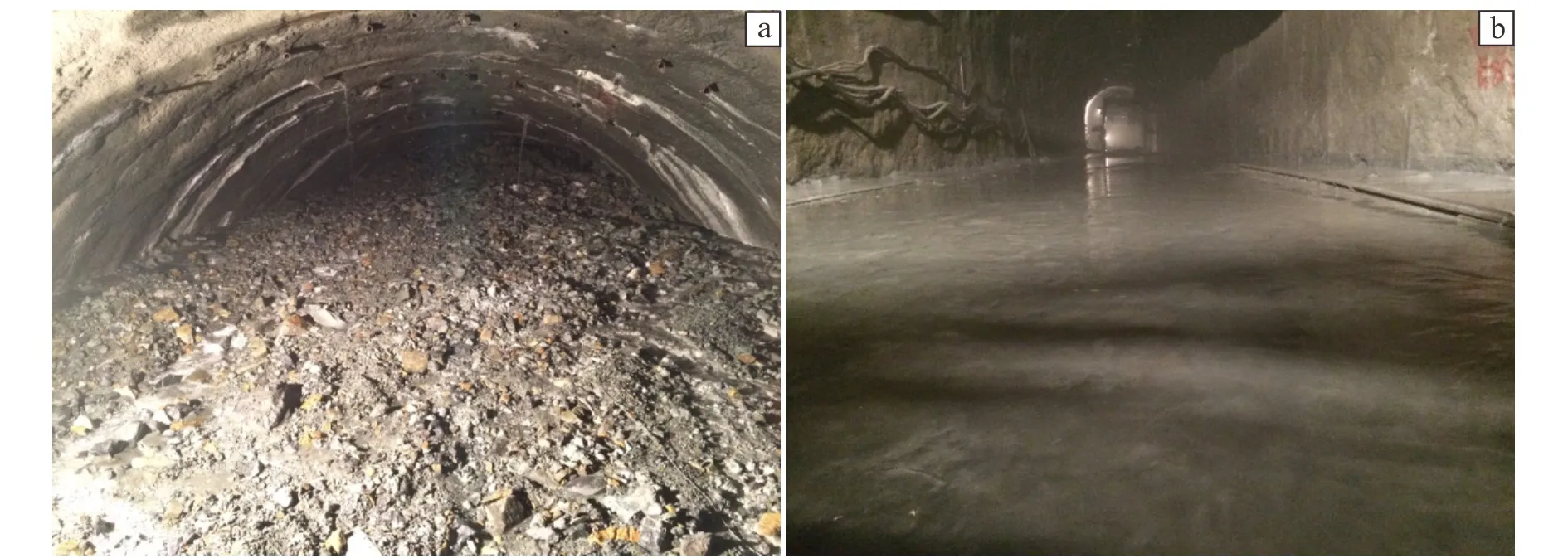
(a) PDK146+195 accumulation of silt; (b) PDK146+400 water and mudy sand.Fig.4 Photos of mud and water inrush from the tunnel
The parallel adit of the tunnel exit was 2 352 m long, and the construction of PDK146+200~+095 revealed in Lower Permian (P1) that the rock in this section is thin layer of grayish black limestone with carbonaceous shale, the limestone is moderately weathered and carbonaceous shale is completely weathered and muddy. The main attitude of rock is N21°E/12°NW and the joints are developed, the rock mass is broken and the integrity is poor.
At PDK146+095, 0.3 m from both side walls, a strand-shaped water flew from the vault 2 m, with the flow rate of about 100 m3/h. The subsequent turbid water quantity gradually increased with mud, and the sediment was entrained with intermittent abnormal sound. After 9 hours, the turbid mud water rushed to PDK146+420, the length was 325 m, after 24 hours was stable at about 700 m3/h (Fig.4).
2.2 Characteristics of geological structures of mud and water inrush in tunnel
Tunnel mud and water inrush means that the surrounding water-bearing geological structure is disturbed due to tunnel excavation, resulting in the deformation and destruction of water-bearing geological structure. This provides space for water and mud mixture to burst into the tunnel.
The basic conditions of disaster occurrence are affected by many factors, such as geological structure, strata lithology, groundwater level, landform, atmospheric rainfall, etc. All kinds of water storage structures provide huge space for groundwater migration and storage. These geological structures include reverse fault, normal fault, interlayer rupture crushed zone, karst, syncline structure, fold and nappe structure.
There are three main conditions for the occurrence of mud and water inrush in the tunnel (Guptaetal., 1984; Luo, 2014):
(1) Engineering construction: during tunnel construction, blasting vibration and excavation work destroyed the aquiclude of various water-storage structures and reduced its thickness. When the thickness of the aquiclude was less than the minimum thickness, the mud and water mixture broke through the aquiclude and rushed into the tunnel.
(2) Rainfall: the groundwater level rised rapidly due to rainfall, and the water volume stored in various systems rapidly increased, and the pressure of the aquiclude increased with the water pressure. When the water pressure was greater than the minimum aquiclude compressive strength, the aquiclude was deformed and damaged, and the mud and water inrush generated at the same time.
(3) Earthquake: Earthquake destroyed the mountain structure and various aquicludes, which made the mixture of mud and water to flow into the tunnel and caused the disaster of mud and water inrush.
Through the investigation of the studied area, it can be found that the hangingwall of Chaoyangcun fault consists of weakly weathered limestone with fully weathered carbonaceous shale. The fault is reverse fault. The carbonaceous shale and fault zone are the aquiclude, while the mud and water inrush position is located in the hangingwall of Chaoyangcun fault, the folds and crumples are severely developed. The rock breakage is affected by structure. The source of water is bedrock fissure water and karst water, which is enriched in the hangingwall and fractured surrounding rock and karst zone. However, during the tunnel construction, the aquiclude was exposed, and huge potential energy of water and mud in the fault was released, causing the disaster of mud and water inrush (Fig.5). So in the studied area, the controlling strcture geological conditions are the reverse faults and folds caused by Xiangyun thrust nappe structure.
The water supply of the three structures is surface water system, rainfall or underground water system lateraly recharged through the permeable layer. The mud and water inrush is large or super-large in scale.
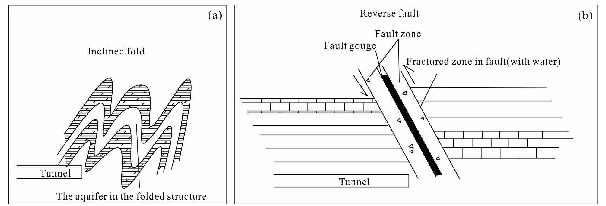
Fig.5 geological models of mud and water inrush
For the thrust nappe structure, it can be divided into double thrust fault, back-flushing thrust fault, etc. As a large geological structure, it has complex structure, gaps, multiple aquicludes and aquifers.complex collocation and connection Water moves across the aquifers between aquicludes and vertically through the fractures in nappe structure, syncline or anticline to form water channels.
For reverse faults, the fractures are well developed with rich water and high water pressure. When they are connected with surface water or underground water-bearing structure, then become groundwater channels.
The folds can be devided into vertical folds, inclined folds and recumbent folds, etc. These kind of water-bearing bodies are mostly layered, concave-convex connected. It transversely passes through the water-bearing strata between the aquicludes to form the water channel, longitudinally through the strata or the joints of the (anticlinal) core and gap to form a connection channel.
3 Prediction method for mud and water inrush
In this paper, the method of induced polarization, transient electromagnetic method and three-dimensional seismic method are used for forecast and relevant analysis.
3.1 Induced polarization method (IP)
Induced polarization method is an important category in electrical exploration. The principle is based on the difference of the polarization effect between different geological media. An electrical method for geological exploration by observing and studying the induced electric effect of the measured object, the detection line is shown in Fig.6.
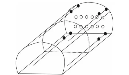
Fig.6 3D induced polarization diagram for advanced detection
The detection needs to calculate the data collected by inversion. This process uses smooth constrained inversion based on observation data and depth weighting. The inversion results can reflect the resistivity structure of the rock and soil in front of the tunnel face. In general, for the area with high resistivity, the surrounding rock is intact with water-deficient, for the area with low resistivity, the surrounding rock is broken with water-rich. Thus interpret relevant geological detection is carried out, the unfavorable geological conditions may exist.
Since the tunnel face of the detection uses three-step excavation, the measurement line of the tunnel face is arranged on the upper step, wherexaxis represents the vertical direction,yaxis represents the width direction of the tunnal face, andzaxis indicates the excavation direction, the inversion area isy(-10 m, 10 m) andx(-10 m, 10 m), and the coordinate of the tunnel face isy(-6 m, 6 m) andx(-5 m, 5 m) (Fig.7) (Zheng, 2019).
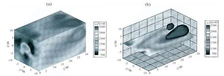
Fig.7 IP 3D imaging (a) and IP imaging (x=0 section) (b) (after Niu et al., 2017 )
As it can be seen in Fig.7:
(1) D1K146+120-D1K146+105: the resistivity is relatively high, it is inferred that the joints are developed and exits water partly.
(2) D1K146+105-D1K146+090: A large low resistivity area appears, it is inferred that the surrounding rock of this section is broken, which is a water-rich fracture zone.
3.2 Transient electromagnetic method (TEM)
The method used the non-ground return line to transmit a pulse magnetic field to the workingface, and when the electricity in the reflected return line was cut-out, a secondary eddy current field was excited in the medium to maintain a magnetic field (primary field) generated before the electricity was disconnected, the size and attenuation of the secondary eddy field were lated to the electrical distribution of the surrounding media, and the change of the secondary field with time was observed in the break of the primary field, and the characteristics of scale, electric property, occurrence of the underground medium can be known after the treatment, then achieved the purpose of detecting the target body (Bu, 2014).
Considering the tunnel geological and electromagnetic environment, the center return line device and point measurement method were selected for this test. The length of the emission wire frame was 2 m, 64 turns, the emission current was1A, and the transmission frequency was 25 Hz. The receiving device was an receiver coil with an effective area of 31.4 m2and a dot pitch of 0.5 m.
In this detection, the line 1 was arranged on the step of the tunnel face D1K146+120 in two directions as line 1a and 1b shown as Fig.8.
From Fig.9, it can be concluded that:
(1) D1K146+120-D1K146+105: the apparent resistivity is relatively high as a whole, it is inferred that fissures are developed in the surrounding rock and exist water in some place;

(a) Schematic dagram of layout of tunnel face; (b) schematic diagram of line layout in different observation directions of line 1.Fig.8 Constraints line layout
(2) D1K146+105-D1K146+078: there is a apparent low resistivity zone, it is inferred that the rock mass is fractured and rich in water;
(3) D1K146+078-D1K146+060: the overall apparent resistivity is low, it is inferred that the rock mass is broken and rich in water.
3.3 Three dimensional seismic method for geological prediction
The principle of this technique is that when the seismic wave encounters an acoustic impedance (the product of density and velocity) difference interface, some signals are reflected back and some signals are transmitted into the forward medium. The variation of acoustic impedance mostly occurs at the geologic in-terface or discontinuous interface in rock (Fu, 2013). When the seismic wave propagates from a low impedance material to a high impedance material, the reflection coefficient is positive, whereas the reflection coefficient is negative.
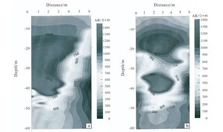
Fig.9 Apparent resistivity profile line 1b (a) and line 1a (b) (after Niu et al., 2017 )
It can be inferred that when the seismic wave propagates from soft rock to hard rock, the deflection polarity of the echo is consistent with the wave source. When there is a rupture zone inside the rock mass, the polarity of the echo reverses. The larger the size of the reflector is, the greater the difference of the acoustic resistance, the more obvious the echo, and the detection accuracy increases.
Since the detection of the working plane was a three-step excavation, the spatial arrangement of the source point in the vertical direction was limited, so the hole layout shown in Fig.10 was adopted.
According to the 3D imaging of reflected seismic waves in the survey area (Fig.11), combined with geological analysis, the following conclusions are drawn:
(1)D1K146+120-D1K146+092: The average wave velocity of the surrounding rock in this section is low, and there is a large amount of reflections. It is inferred that the entirety surrounding rock of this section is broken.
(2)D1K146+092-D1K146+060: The average wave velocity of the surrounding rock increases slightly, and there is partly strong reflection in the section. It is inferred that the surrounding rock is more intact than above with broken surrounding rock.
(3)D1K146+060-D1K146+035:The wave velocity of the surrounding rock gradually increases, but decreases near D1K146+055 with partly continuous strong reflection with broken surrounding rock.
(4)D1K146+035-D1K146+020: The wave velocity of the surrounding rock increases gradually, and there is a little strong reflection. It is inferred that the surrounding rock is more intact than above, with overall poor integrity and partly broken surrounding rock.
Considering the detection results of the mentioned three methods and the geological analysis, it can be inferred that the surrounding rock is broken in overall and rich in water, and existing water-rich fracture zone, therefore, there is a risk of large scale mud and water inrush disaster.
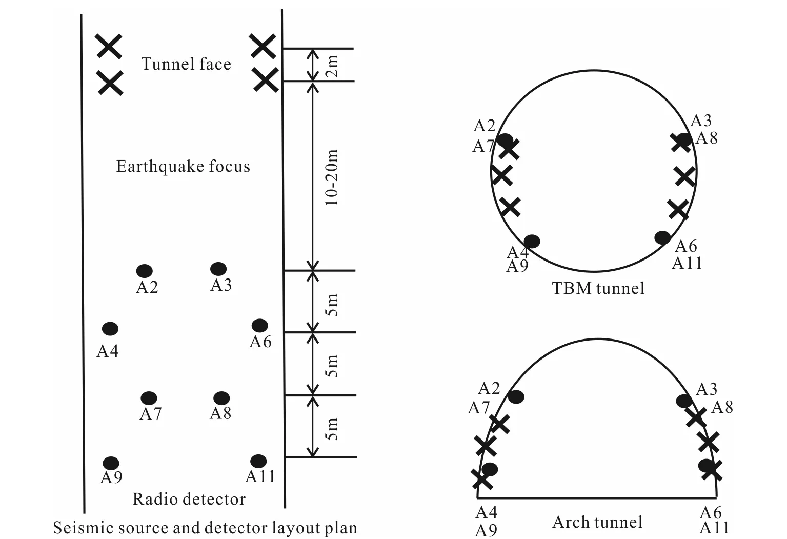
Fig.10 Borehole and detector layout map
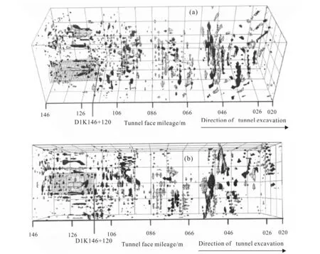
(a) Vertical view; (b) front view.Fig.11 3D imaging map of reflected seismic waves for D1K146+120 (Niu et al.,2017)
4 Disaster treatment and construction plan
Firstly, install two 200 mm steel drainage pipes, backfill with woven bags 5 m behind theface, then apply 2 m C25 concrete retaining walls,and weld 14 I-beam inside the wall and connect it to the initial support I-beam in the grouting wall. After that the concrete is filled, the ballast of the wall base is grouted and consolidated. Radial drainage holes are applied in the range of 5 to 10 m from the working plane, and radial grouting is conducted in the range of 10 to 50 m. After construction of the grouting wall, the C25 fine aggregate concrete is pumped in the collapse cavity according to advance geology forecast 、Infrared water detection and horizontal borehole, etc. The concrete is 5 m higher than the dome. Then further strengthen the surrounding rock under the pipe shed. Finally, the second and third sections of the grouting wall are gradually removed depending on the unfavorable geological conditions. The inverted arch in the dangerous section is perfused every 3 m.
At the same time, according to the field conditions, the cement-sodium silicate binary slurry is chosen for the ground and cavity grouting. Its advantages are that the grouting and gel time is controllable, with better injectability, and applicable in the stratum with high permeability, and its high early strengthis conducive to excavation construction immediately after grouting (Yang, 2011).
4.1 Material selection
Material selection is described as follow,and the water quality of the mixture follows the Code for Construction of Railway Concrete and Masonry Works.
Ordinary portland cement over 425 (W/C=0.8) in accordance with the standards is used with water glass with original concentration of 42--45 Bé, proportion of 1.42--1.45, Module 2.4--2.8 (diluted concentration: 25--35 Bé), water cement ratio:W/C=0.8, the volume ratio(C/S) is 1∶0.5--0.7. When the water glass concentration reduced or the water-cement ratio increases, the gel time will increase, and the initial and final condensation will be slow.The chemical pulp is phosphoric acid solution (ρ=1.7 g/cm3; P/W=1∶10). Coagulation time of the general section is 3 minutes, and that of the water-rich section is 1--2 minutes.
Its construction control can be divided into the following three types (Li, 2010):
(A) Singly change the double pulp ratio, when the proportion of water glass solution increases, the gel time will shorten, and the initial and final coagulation will accelerate.
(B) Singly change the water cement ratio, when the water cement ratio increases, the gel time will shorten and the initial and final coagulation will accelerate.
(C) Singly change the water glass concentration, water glass concentrationdecreases, the gel time will increase, and the initial and final coagulation will accelerate.
According to the amount of water produced to determine the grouting mode, stop drilling immediately if water appears in the drilling process, use grout-drill alternate grouting until the full designed section is completed.
When there is no water yield, using full hole primary grouting; when it is less than 2 m3/h, drilling one-time to the design hole depth then use the one-time grouting method; when it is between 2--10 m3/h, choosing forward grouting; when it is more than 10 m3/h, using single-double liquid circulating grouting grouting method, or retrograde grouting with stop-grouting plug when necessary.
In the case of high water pressure and large amount of water, this paper adopts stratified drainage decompression and layered grouting: the lower pipe is for grouting, the middle pipe is for draining; the middle pipe is for grouting, the upper pipe is for draining, so the water is lifted layer by layer, discharged to the outside of the water streosphere above the vault.
The water-off operation is the key to the success of water blocking. Because the water outlet point is close to the left upper side of the working surface, it is possible to crack the grout wall after the water is closed, so that the surrounding rock and the retaining walls must be monitored. After the initial grouting, in order to prevent the secondary disaster, curtain grouting must be carried out on the working face to push the water to the surrounding rock which is far from the excavation contour. Because there are gaps between the top of the retaining wall and the vault rock, in order to avoid the water flowing out from the gap, it needs to be sealed by grouting first (Zhou, 2006).
The final pressure of the grouting is determined by the inrush water pressure. During the grouting process, the crack size in the surrounding rock is different, and the fissure water may be connected to the surface to lead to a lack of grouting pressure . In this case, the grouting pressure can only be controlled by the grouting speed. The drilling water yield is greater than 50 L/min, and the grouting speed is 80--100 L/min. When the drilling water yield is less than 50 L/min, and the grouting speed is 60--80 L/min, if necessary, adjust the seriflux mix ratio and gel time, and the effective range of grouting is 4.0 m away from the excavation contour line.
4.2 Double tube process features
The hole in the grouting process is made by the TXU-200 drilling rig. The drill pipe is φ42 hollow. After the drilling rig is placed, adjust drill pipe angle to align the hole position, the rig cannot be moved. The grouting hole is lay out in quincuncial and the grouting construction is back grouting (Fig.12).
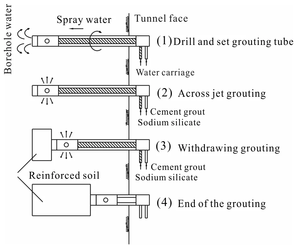
Fig.12 Backward grouting diagram (Niu et al., 2017)
The same grouting consolidation effect can be achieved by double tube grouting and pipe shed grouting in the excavation section, but the double tube grouting is more effective for the working plane to start to excavated after grouting. The same pipe is used for drilling and grouting, avoiding problems such as collapse of holes when drill pipe and porous channel are separated, and reducing the time and material for removing the grouting pipe and shed pipe during excavation.
5 Conclusions
(1) Mud and water inrush in tunnel is the disturbance of the water-bearing geological structure around the tunnel during the excavation. The gravity stress causes the deformation, instability and flow of the water-bearing geological structure, causing the mixture of water and mud suddenly surges into the tunnel,jeopardizes the safety of tunnel construction workers and equipments.
(2) In addition to the water storage and the space for energy release, there are three main induced disaster conditions, including engineering construction, rainfall and earthquake.
(3) Through the analysis and research on the geological model and characteristics of the tunnel in combination with the above three advanced prediction, a series of treatment schemes are put forward in view of the damage situation in the working area: the cement-water glass double liquid slurry is chosen for the grouting materials in the ground and the hole, the advantage of which is that the gel time is controllable, and it has good injectability and high early strength, and the grouting adopts retrograde grouting construction with mature craft, which reduces the time of grouting fashion pipe and improves the excavation efficiency.
杂志排行
Global Geology的其它文章
- Zircon U-Pb geochronology and geochemistry ofgranite in Huoluotai area of northern Great Hinggan Range
- Identification model of geochemical anomaly basedon isolation forest algorithm
- Regularized focusing inversion for large-scalegravity data based on GPU parallel computing
- Logging interpretation method for reservoirs with complexpore structure in Mesozoic-Cenozoic faulted basinaround Daqing exploration area
- Slope reliability analysis based onMonte Carlo simulation and sparse grid method
- Mode decomposition methods and their application inground penetrating radar data processing
