A Numerical Investigation on Cooling Effectiveness for Advanced Fan-shaped Film Cooling
2019-07-23XuLiYanjingQuLiuliSong
Xu LiYan-jing Qu Liu-li Song
(AECC Shenyang Engine Research Institute,Shenyang,China)
Abstract:As one of the advanced film cooling scheme, fan-shaped hole exhibits significant improvement in filmcooling effectiveness compared with cylindrical holes. In this paper, numerical simulations are applied to predict thecooling effectiveness for fan-shaped hole at various flow conditions. The flow conditions are evaluated at three blowingratios (0.5, 1, 1.5) and four mainstream Mach numbers (0.3, 0.45, 0.6, 0.75). CFD simulations are performed in threeRANS turbulence models namely realizable k-ε model, SST k-ω model and standard k-ε model. Simulation results arecompared with experimental data in terms of centerline adiabatic cooling effectiveness, the realizable k- ε model showsa better agreement in predicting the film cooling performance. Although some agreements are obtained, all the threeturbulence models tend to overpredict the cooling effectiveness compared to experimental data.
Keywords:Film Cooling, CFD,Turbulence Models,Adiabatic Cooling Effectiveness
0 Introduction
During past 70 years,there has been a very significant increase in turbine entry temperature(TET)in order to improve gas turbine performance,currently TET has reached to about 2000°C around year 2010 for the advanced gas turbine,but at the same time,the temperature limit of current Nickel based super-alloy for turbine blade is about 1100°C[1].Currently,blade cooling technology is a complex combination of multiple different cooling techniques,among these,film cooling[2]is one of the most common ways to provide cooled protective layer between the hot gas and the external surfaces of gas turbine blades through discrete film holes by blowing of cooling air extracted from compressor.
Researches on film cooling have revealed that film hole shapes have significant impacts on film cooling effectiveness.Goldstein et al.(1974)firstly used a cylindrical hole with a conical diffusing section and measured effectiveness downstream of the hole[3].They found that the jet remained near the surface with mainstream flow applied,and the centerline effectiveness was comparable with slot cooling,the lateral variation in effectiveness was significantly reduced compared with conventional cylindrical holes.Haven et al.(1997)found the conical diffuser could also improve film cooling coverage[4].Gritsch et al.(1998)and Thole et al.(1998)present adiabatic cooling effectiveness and flow field measurements for two types shaped holes:fan-shaped hole and laid-back fan-shaped hole[5-6],the exit expansion in these shaped holes reduces the velocity and hence the momentum of the coolant flow,so that the jet penetration is decreased,leads to improve the cooling effectiveness.Sargison et al.(2001)presented that a converging slot hole(console),which showed same cooling performance compared with fanshaped holes,but significantly reduced aerodynamic loss[7].Besides that,investigations are performed for many other shaped film holes[8-11],and numerical simulations are also widely applied to investigate film cooling besides experimental studies[12-15],generally numerical simulations are able to capture visible detailed flow and temperature filed despite of the measurement limitations in the experiments.
1 Fan-shaped Film Cooling Simulations
1.1 Geometry of fan-shaped hole
Gritsch et al(1998)provided measurements on flow field and cooling effectiveness on three different film hole geometries:a cylindrical hole,a fan-shaped hole and a laidback fan-shaped hole[5][16].In this paper,numerical study concerning fan-shaped film hole cooling performance is based on these experiments.
The detailed schematic of fan-shaped film hole is shown as Fig.1.Single,scale-up fan-shaped hole with a 30°inclination angle α was applied.The fan-shaped film hole included two sections:a cylindrical inlet section and an ex-panded outlet section.At the inlet,the diameter of the cylindrical hole was 10 mm with a length-to-diameter ratio of 2.The lateral expansion angle β for the fan-shaped film hole was 14°,leading to a width of 30mm at the expanded outletsection,the length of the expanded section is 40 mm,resulting an outlet-to-inlet area ratio of 3.0.All the hole geometry parameters were well balanced to enable an increased flow expansion before the coolant flow entering the expansion section hence encourage flow diffusion,and it also limited the flow separation at the outlet so as to improve the coolant flow coverage.
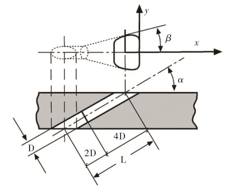
Fig.1 Schematic of fan-shaped hole geometry
1.2 Computational domain
The computational domain in this numerical investigation matches the film cooling test section,according to the test condition,the computational domain mainly consists of three parts:a primary channel which simulates the mainstream,a secondary channel which is adapted to deliver the coolant,the coolant passes through the fan-shaped film hole between the primary channel and secondary channel and then injects into the mainstream.As shown in Fig.2 and Fig.3 the width and height for the primary channel are 90 mm and 41 mm,respectively,and the secondary channel is 60 mm in width and 20 mm in height.The diameter of the fan-shaped film hole at the inlet section is 10 mm,resulting in a 3.0 owclet-to-entry area ratio of the fan-shaped film hole.The outlet plane of the mainstream is located at 15D downstream the centre of the hole outlet.

Fig.2 Schematic structure of computational domain
1.3 Grid
In this study,commercial software ICEM CFD was applied to generate multi-block structured grid.Grid independence was obtained through solution-based adaption,the medium mesh with a total element number of 3 288 744 was selected for all the simulations,for the whole computational domain,the mesh quality for all the cells are above 0.3,which indicates the mesh quality are reasonable for the simulation,the first point above the bottom wall of the primary channel is about 0.004mm,which results in the average Y plus value around 1 at this surface.Fig.4 shows the overview of the final grid used in this study,boundary layer refinement are also detailed in the near wall regions of the side walls of the primary channel,the side walls of the film coolant channel,and the walls of the fan-shaped film hole.
1.4 Turbulence models and test cases
The simulations were carried out by applying the commercial CFD codes Fluent 14.0 software.The particular solver was pressure correction to achieve the pressure-velocity coupling by multi-grid acceleration.In the three dimensional computational domain with structured grid,steady,time-averaged Navier-Stokes equations were processed and pressurebased SIMPLEC solver with second-order upwind discretization schemes were used.

Fig.3 Solid model of computational domain

Fig.4 Mesh overview of the computational domain and mesh details in the film hole region
The flow parameters investigated in a matrix in this study are shown in Table 1,in order to obtain the basic flow characters and film cooling mechanism for fan-shaped film hole,a baseline case is set at selected flow condition(Mac=0.6,Mac=0,M=1),here Macand Macare main stream and coolant flow Mach number respectively,and M refers to blowing ratio.Besides that,seven other test cases are classified into three groups to investigate the effects of flow parameters on film cooling effectiveness.
In order to evaluate the performance from different turbulence models to predict fan-shaped hole cooling perfor-mance,three RANS turbulence models,namely the standard k-ε(SKE)with enhanced wall treatment,the SST k-ω model and realizable k-ε(RKE)model are examined in various flow conditions in this study and compared with published experimental data[5].

Tab.1 Test case matrix
1.5 Boundary Conditions
All the other surfaces of the computational domain were set to isothermal no-slip wall condition where the heat flux through the wall was specified to be zero.The inlet turbulence intensities for the mainstream and coolant channel are specified to 1.5%and 1%respectively.
In order to achieve the expected flow conditions include and blowing ratio M,pressure inlets are adopted both for the primary channel(mainstream)and secondary channel(coolant),likewise,pressure outlets were specified at the outlet of the both channels,static pressures and total temperatures were given at the outlets.In the baseline case,mainstream inlet total pressure is 93800Pa and static pressure at the outlet is 68000Pa,coolant flow inlet total pressure is 100520Pa,for the other test cases,both the primary channel and secondary channel pressure at the inlets varies to satisfy the determined flow conditions.In all test cases,the coolant Tcand the mainstream total temperatures T∞are selected to be 290K and 540 K respectively and consistent with experiment condition[5],hence the temperature ratio(Tc/T∞)is set to 0.54 and kept constant,which represents for typical gas turbine air cooled blade operational condition.
2 Results and Discussion
2.1 Baseline case
Since the flow field directly affects the interaction between the mainstream and coolant and hence influences film cooling performance,flow field hence is a very important issue in film cooling simulation.
In the baseline condition(Mam=0.6,Mac=0,M=1),three turbulence models are applied to run the simulations.Results show complicated flow structure in the film hole and the near hole region.It is clear that all the three turbulence models are able to predict the jetting region with high momentum at the leading edge within film hole,the relatively high momentum jet does not pass through the film hole with fully expansion.Besides that,the flow separation due to the large turning at the trailing edge of the inlet is observed and hence a low momentum region appears along the trailing edge(See Fig.5).

Fig.5 Near hole region velocity magnitude contour(m/s)for the central plane(Y=0)at baseline case(Mam=0.6,Mac=0,M=1)
Fig.6 and Fig.7 clearly reveal that the coolant jet interaction with the mainstream along the stream-wise distance.Thanks to the laterally diffusion within the fan-shaped hole,the jet lift-off effect is not as pronounced as conventional cylindrical film holes,the counter-rotating vortex pair(CVP)is restrained by the anti-CVP and hence delays jet lift-off and penetration into the mainstream.The effect of CVP on film cooling effectiveness was reported by Haven et al(1997)[17].
Firstly,increased lateral separation reduces the mutual induction between the counter-rotating vortices and delays the jet lift-off.Second,fan-shaped holes are found to generate anti-counter-rotating vortex pair(anti-CVP with an opposite rotation sense relative to CVP.The anti-CVP,the presence and the formation of anti-CVP can cancel the adverse effect of the CVP so as to prevent the jet lift-off.
The centerline and laterally averaged film cooling effectiveness over the downstream surfaces are calculated in three different turbulence models:a)RKE,b)SST,c)SKE model.These computed results are compared with experimental data in this section.As it is shown in Fig.8,the two dimensional local effectiveness predicted by RKE and SKE are very similar to each other,results from all three model are different from the experimental data to some extent,where adiabatic cooling effectiveness is relatively high along the centreline in the experiment,the difference possibly because of they are not conjugate simulations and only fluid domains are solved[15].Besides that,on average,the predicted cooling effectiveness distributions in present study are higher than the experimental data.
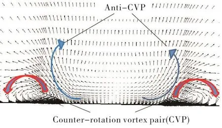
Fig.6 Velocity vector in Y direction at x/D=0 plane obtained by RKE model at baseline case
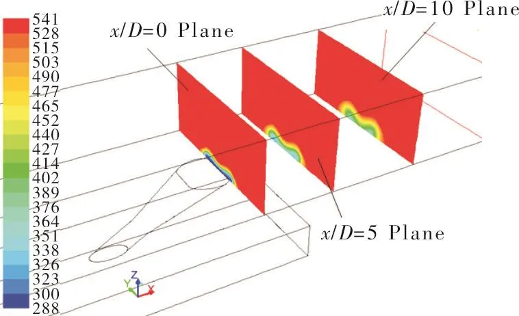
Fig.7 Total temperature contour predicted by RKE model at baseline case
The centerline cooling effectiveness results predicted by three turbulence models are shown in Fig.9.All the three models show the same tendency of centerline cooling effectiveness,it decreases steadily along the stream-wise distance,due to the jet lifts off the wall and mixes with the mainstream gradually.But compared with the experimental data,all the three turbulence models over-predict the centerline cooling effectiveness,especially at the near film hole region(x/D<3).That may be due to the fact that the conduction in the experiment cannot be neglected.

Fig.8 Local cooling effectiveness predicted by three different turbulence and comparisons with experimental data
2.2 Effect of blowing ratio on cooling effectiveness
The effects of blowing ratio on the film cooling performance are simulated at three different blowing ratios(M=0.5,1.0,1.5),where the mainstream and secondary channel flow condition remain the same(Mam=0.6,Mac=0).Three turbulence models(RKE,SKE,and SST)are applied to predict the cooling effectiveness and compared with experimental data.
As shown in Fig.10 to Fig.12,at all three blowing ratios,the same as the experimental data,three turbulence models predict a consistence reduce in the cooling effectiveness downstream the coolant ejection.Moreover,with the increase of the blowing ratio from 0.5 to 1.5,the coolant tends to concentrate on the centerline,causing larger cooling effectiveness gradient at lateral directions.Generally,fan-shaped hole provides a better coverage and lateral spreading than the cylindrical hole at all blowing ratios,mainly because only limited jet separation happens near the film hole compared with conventional cylindrical hole.
According to the experiment conditions,for fan-shaped hole,the centerline cooling effectivenessηis influenced by the blowing ratio,at low blowing ratio(M=0.5),the centerline cooling effectiveness decreases dramatically,increasing the blowing ratio from 0.5 to 1.0 results in improved cooling effectiveness,but further increasing the blowing ratio from 1.0 to 1.5 slightly reduces the effectiveness in the x/D<8 region.
Generally,the predictions of RKE provide better agreements with the experimental data relative to other two turbulence models.Although the predicted values are much higher than the experiment results,the main tendency of the RKE simulation results match the experimental data well,the effect of blowing ratio on the centerline cooling effectiveness is revealed clearly in the simulation.The overall deviation of cooling effectiveness is about 0.1 at higher blowing ratio(M=1.0,1.5)and about 0.2 at lower blowing ratio(M=0.5).

Fig.9 Centreline local adiabatic cooling effectiveness for three turbulence models at baseline case

Fig.10 Centreline adiabatic cooling effectivenessforRKE simulation at different blowing ratios

Fig.11 Centreline adiabatic cooling effectiveness forSST simulation at different blowing ratios
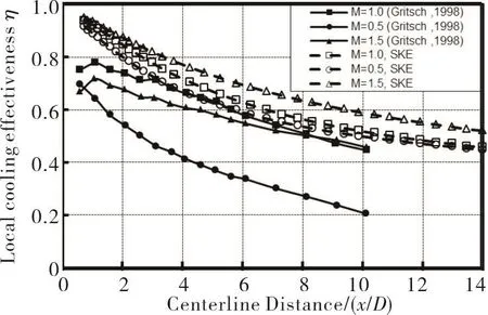
Fig.12 Centreline adiabatic cooling effectiveness for SKE simulation at different blowing ratios
2.3 Effect of mainstream on cooling effectiveness
To evaluate the effect of mainstream Mach number on the film cooling performance,four representative mainstream flow conditions(Mam=0.3,0.45,0.6,0.79)are selected in present study.Three turbulence models are applied at each mainstream flow condition with the same coolant channel flow condition and blowing ratio(Mac=0,M=1),the performance in predicting cooling effectiveness for three turbulence models are compared.
Theoretically,as the mainstream flow Mach number increases,the coolant-to-mainstream pressure ratio needs to be increase correspondingly,resulting in that more coolant is injected along the centerline of the fan-shaped hole,which means lateral expansion of the coolant jet is decreased,consequently,the lateral cooling effectiveness is reduced as the mainstream Mach number increases.
Generally,higher coolant-to-mainstream pressure ratio is needed to maintain the same blowing ratio as the mainstream flow Mach number increases from 0.3 to 0.79,as a result,much more coolant is injected along centerline of the film hole.Hence,the centerline cooling effectiveness is improved gradually as the mainstream flow Mach number increases.The simulation results of centerline cooling effectiveness obtained by both RKE model and SKE model match the trends well.

Fig.13 Centerline local adiabatic cooling effectivenessηfor RKE simulation at different mainstream Mach numbers
3 Conclusions
The effects of flow parameters on fan-shaped film cooling effectiveness have been numerically investigated based on three turbulence models:RKE,SST and SKE.The performances to predict film cooling effectiveness for three models are also evaluated by comparing with experimental data.
1)Simulation results show that all the three turbulence models are able to predict the main trends of the film cooling effectiveness along the streamwise distance,and the effects of evaluated blowing ratios,mainstream Mach numbers and coolant flow Mach numbers are not pronounced as conventional cylindrical hole.
2)Generally,the RKE model has a better performance in predicting cooling effectiveness at evaluated test cases.
3)Although a few agreements are obtained between the simulation results and the experimental data,all the three turbulence models tend to overpredict the cooling effectiveness downstream the film hole exit and the deviation is about 0.1~0.2.
