Rapid Interactive Design-to-Performance of Mixed-Flow Space Inducers
2019-07-23LucaAgostino
Luca d'Agostino
(Civil and Industrial Engineering Department,University of Pisa,Pisa,Italy,luca.d'Agostino@ing.unipi.it)
Abstract: A flue gas circulation duct design system based on numerical calculation and experimental test is establishedfor two induced draft fans of a 330MW coal-fired unit in China. Firstly, according to the safe and economic operation of theinduced draft fan, the design of circulating air volume is selected. Then, 9 design schemes of flue gas circulation duct are putforward, 9 schemes are compared and selected by numerical method, and design scheme 5 (φ=1.2m) is selected with overallconsiderations. Lastly, when the flue gas circulation duct reformation is completed, the field thermal performance experimentis carried out in the 300MW condition with normal combustion of the boiler. The experimental results demonstrate that withthe flue gas circulation duct,the circulating air volume of the circulation duct, the safety reliability and working efficiency ofthe induced draft fans can reach the design expectations.
Keywords: Induced Draft Fan; Flue Gas Circulation Duct; Numerical Calculation; Experimental Test; Design System
Nomenclature
Latin Symbols
a distance of the leading edge from the maximum camber point
B flow blockage
c blade chord
cafull-blade axial length
c%tip clearance/mean blade height ratio c%=δ/hm
D diameter,diffusion factor
Dchhydraulic diameter of blade channels
eϑunit vector in azimuthal direction
f friction coefficient
h specific enthalpy
hmmean blade height
L axial length
Lcheffective length of blade channels
Leqequivalent duct length
McCarter's rule coefficient
N number of blades
p,ptstatic and total pressures
P (local)blade pitch
Q volumetric flow rate
r position vector
r radial coordinate
Reδtip clearance Reynolds numberReδ=2ΩδrT/v
rHinducer hub radius
rMinducer mean radius
rTinducer tip radius
s azimuthal blade spacing
T flow temperature
u flow velocity
u radial ftov velocity
U freestream boundary layer velocity
v azimuthal flow velocity
V absolute value of the flow velocity
w axial flow velocity
z axial coordinate
Greek Symbols
βbblade angle evaluated w.r.t.the azimuthal direction
β'2relative discharge flow angle without deviation
γ blade angle from axial direction
δ boundary layer thickness,blade tip clearance
δ*boundary layer displacement thickness
δ°discharge flow deviation angle
ϑ azimuthal coordinate
θ*boundary layer momentum thickness
ρ flow density
v kinematic viscosity
σ blade solidity,cavitation no.Φ=(p1-pv)/ρΩ2
Ψ slip velocity stream function
Ψ static head coefficientsΨ=(p2-p1)/ρΩ2
Ψttotal head coefficientsΨt=(pt2-pt1)/ρΩ2
Ω inducer rotational speed
Ω inducer rotational speed(vector)
Special Notations
q' value of q in the rotating framemean value of qfully-guided flow velocity slip flow velocity
Subscripts
D design conditions
T tip radius
h high clearance
H hub radius
l low clearance
le leading edge
te trailing edge
δ°flow deviation angle
1 upstream station
2 downstream station
Acronyms
BVP Boundary Value Problem
CPRTF Cavitating Pump Rotordynamic Test Facility
ODE Ordinary Differential Equation
2D two-dimensional
3D three-dimensional
1 Introduction
Current rocket propellant feed turbopumps often employ an inducer upstream of the centrifugal stage in order to avoid unacceptable cavitation,improve the suction performance and reduce the propellant tank pressure and weight.The main purpose of inducers consists in sufficiently pressurizing the flow for the main pump to operate satisfactorily.Compared to centrifugal pump impellers,typical inducers have fewer blades(usually 3 or 4),lower flow coefficients(from 0.05 to 0.1),larger stagger angles(70°to 85°)and significantly higher blade solidities(between 1.5 and 2.5).Long blades with small angles of attack provide ample time and room for the collapse of the cavitation bubbles and for the gradual exchange of energy with the flow.The resulting configuration,even though beneficial from the standpoint of cavitation performance,results in relatively low values of the inducer efficiency due to the highly viscous,turbulent and dissipative flow inside the blade passages.
The development of three-dimensional(3D)theoretical models capable of rapidly predicting the performance of axial inducers in order to provide indications for the preliminary design of the machine is of particular interest to rocket engineers.However,not many such models have been proposed so far,probably due to the difficulty of adequately describing the 3D flow field inside the inducer blades.Therefore,designers often refer to simple“rules of thumb”or to the general indications of design manuals such as the one published NASA(Jakobsen,1971)[1].In the past decades,numerical simulation of the complex 3D features of inducer flows has emerged as a promising tool for design validation and refinement(see,for example,Ashihara et al.,2002;Kang et al.,2007)[2-3],but its use in the stages of design still remains impractical.
A number of two-dimensional models for the prediction of the noncavitating flow in turbopump inducers have been illustrated by Brennen,1994,1995[4-5].These models are based on linear and radial cascade analyses with semi-empirical inclusion of flow deviation and viscous effects.Three-dimensional corrections for inlet flow prerotation,leakage,and discharge flow are also indicated.More recently Lakshminarayana,1982[6],addressed the problem of performance prediction of noncavitating inducers by the combined use of a simplified radial equilibrium and the Euler equation.Viscous effects are taken into account through an empirical loss coefficient deduced from the reported performance of inducers documented in the literature.Indications on the effects of solidity and number of blades are also provided.
A second class of models has been aimed at the prediction of the effects of cavitation on inducer performance(Stripling and Acosta,1962;Cooper,1967;Brennen and Acosta,1973;Brennen,1978)[7-10].Also these models are essentially two dimensional,where cavitation is assimilated to a vapor layer on the blade or a mixture of bubbles and liquid.Early studies opened the way to a number of more recent analyses capable of better understanding and predicting the major flow instabilities affecting cavitating inducers(see,for instance,Tsujimoto et al.,1993,1998;Watanabe et al.,1999;Semenov et al.,2004;Pasini et al.,2011)[11-15].
In 2007,Bramanti et al.,2007[16],developed a simplified model based on the traditional throughflow theory approximations with empirical corrections for incidence,friction,and deviation losses of the flow through the inducer blades.The model proved to be in good agreement with the reported performance of several inducers tested in different facilities worldwide.
Expanding on this exploratory work,d'Agostino et al.,2008a,2008b,2008c[17-19],developed and successfully tested a quasi-3D reduced-order model for the preliminary geometric definition and noncavitating performance predic-tion of tapered axial inducers,whose results have been later extended by means of the similarity experiments by Torre et al.,2009[20],to account for tip leakage effects.The present invited lecture illustrates and summarizes the main features and results of these investigations.Later analyses by Cervone et al.,2012[21],also investigated the effects of the leading edge shape on the performance of helical inducers.Extension of the present model to the simultaneous geometry definition and performance prediction of centrifugal turbopumps has recently been carried out and validated by d'Agostino et al.,2012,2017a,2017b[22-24].
Under the assumptions of incompressible,inviscid and irrotational flow,the 3D velocity field inside the blade channels has been approximated as the superposition of a 2D cross-sectional vorticity correction on a fully-guided axisymmetric flow with radially uniform axial velocity.Suitable redefinition of the diffusion factor to bladings with non-negligible radial flow allowed for integral control of the blade loading and for the estimate of the boundary layer blockage at the specified design flow coefficient,providing a simple way to better match the hub profile with the axial variation of the blade angle in variable-pitch tapered inducers.Carter's rule has been used to account for flow deviation at the inducer trailing edge.Mass continuity,angular momentum conservation and the Euler equation have been used to propagate the solution downstream and derive a simple 2nd order boundary value problem(BVP),whose numerical solution determined the steady,axisymmetric,axial flow at the inducer discharge.Finally,the non-cavitating pumping performance has been obtained by correcting the Euler head by means of suitable correlations for turbulence losses,flow incidence and deviation.The model has been validated by comparing its results with the experimental data obtained in the Cavitating Pump Rotordynamic Test Facility(CPRTF)for some space rocket inducers of European design and with the reported performance of a number of inducers tested in Japanese laboratories(Cervone et al.,2005,2006,2007)[25-27].Head correction for tip leakage effects has been carried out based on the results of the similarity experiments by Torre et al.,2009[20],on a three-bladed inducer designed according to the indications of the present model.Comparison of the pumping performance and geometry a number of high-head inducers documented in the literature confirmed the validity and accuracy of the proposed midel.
2 Inducer Flow and Geometry
2.1 Flow Velocity
The incompressible,inviscid,irrotational flow through a helical inducer withNradial blades,rotational speedΩ,constant tip radiusrT,tapered-hub radiusrH,variable axial pitchP,and blade angleγ(as schematically shown in Fig.1)is held by the equations:

The relatively large value of the blade solidity typical of inducers designed for controlling cavitation in highly loaded turbopumps suggests that near design conditions(Φ≅ΦD),the 3D velocityuthe blade channels can be approximated by the superposition of a guided axisymmetric flow a with radially uniform axial velocity componentand a 2D cross-sectional slip velocity correction(Fig.2):

With reference to the velocity triangles of Fig.3,for radial helical blades:

where0≤B≤1is the average cross-sectional blockage due to the boundary layer displacement effects and,if significant,to blade thickness.The 2D slip velocity components are most synthetically expressed and solved for in terms of a scalar stream functionΨ( )r',ϑ'in the rotating cylindrical coordinatesr'=r,ϑ'=ϑ-Ωt,andz'=z:


Fig.1 Inducer schematic and nomenclature

Fig.2 Schematic of the 2D cross-sectional slip velocity correction in the inducer blade channels
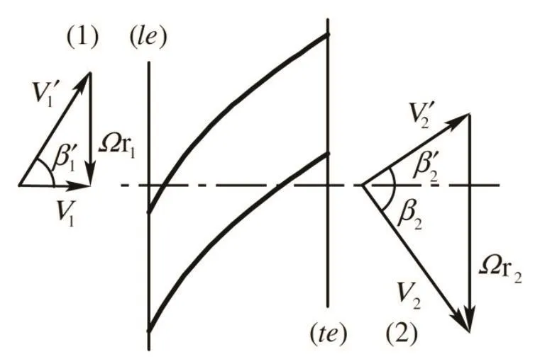
Fig.3 Velocity triangles
2.2 Inducer Tip and Hub Radii
Substitution of the assumed velocity field in the expressions of the incompressibility and irrotationality conditions in cylindrical coordinates r,ϑ,z yields:

Integration ofd2/dz2=0with the boundary conditions(0)=leand(ca)=teat the axial locations bounding the full-height portion of the blades(indices le and te)yields:

and the following expression for the axial velocity:

Similarly,integrating the continuity equation with the impermeability condition(rτ)=0at the tip radius,the following expression for the radial velocity is obtained:

Finally,evaluatingwat design conditions(index D)by means of the continuity equation and integrating d=/P)dz=0withP(leD)=PTleatz=0,the following expressions for matching the axial changes of the hub radiusrHand blade pitchPare obtained:

where:

and a linear axial variation of the blockage can be approximately assumed inside the blade passages from the leading edge station(le),whereB=Ble≅1,to the trailing edge(te)whereB=Bte.The assumption of no leading edge blockage implies zero blade thickness,no leading edge separation,and zero initial boundary thickness.Given the relative magnitudes of blade and boundary layer thicknesses and the level of accuracy of the present model,these effects can be considered of second order and therefore have not been taken into account.
2.3 Slip Flow
Finally,on each channel cross section,Poisson's equation for the stream function can be conformally mapped in a rectangular domain and integrated standard methods(Hildebrand,1976)[28]with the conditionΨ=0on the boundary to:

where:

and

from which the radial and tangential slip velocity componentsandare readily computed.
2.4 Blade Loading and Boundary Layer Blockage
With reference to Fig.4,suitable redefinition of the diffusion factor for axial bladings(Lieblein et al.,1953)[29]:

to the case of tapered inducers with non-negligible radial flow allows for the control of the blade loading(a crucial design aspect under cavitating conditions)and the estimate of the boundary blockage at nominal flow conditions.
By evaluating:

with Bernoulli's and Euler's equations for mixed-flow bladings and substituting in the above expression forDobtain:


Fig.4 Nomenclature for blade boundary layer(a)and linear cascade(b).
Here all relevant properties including the solidityσ=c/s are evaluated on the mean streamline:

and,for flow with no inlet prerotation and fully guided at the inducer outlet(v1≅0and≅wtetanγte)the relative velocities are expressed by:
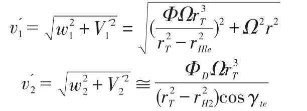
As illustrated in Fig.5,in turbulent boundary over blade cascades)the diffusion factor is correlated with the momentum thicknessθ*(Lieblein,1965;Brennen,1994)[30,4]:


Fig.5 Ratio of the momentum thicknessϑ*of the blade boundary layer to the chordcas a function of the diffusion factorD,for axial cascades with three different profiles(adapted from Brennen(1994))[4].
Furthermore,by using the Prandtl equations for the turbulent boundary velocity profile on a fiat plate(Prandtl and Tietjens,1934;White,1974)[31-32],it is possible to show that the displacement thickness is δ*≅1.3θ*.With these results,the blade boundary layer blockage at the inducer edge is computed as:

(Fig.4)where the blade spacingSte=2πrte/Nis evaluated at the mean radius.
2.5 Mean Radius,Chord,and Solidity
On a relative streamline of the guided flow:

where from earlier results:

Hence,integrating with initial conditionsrMle,ϑ'Mle,zMle,the equations of the mean streamline are:

The mean values of the blade chord and are then evaluated as:

2.6 Flow Pressure in the Blade Channels
The pressure of the(absolutely)irrotational flow in the blade channels can readily be obtained by straightforward integration of steady Bernoulli's equation in the reference frame r,ϑ',zrotating with the inducer:

where the same integration constant:

applies over the entire flow field,and the velocityu'is expressed by:

Therefore,with earlier notations:

and,solving for the flow pressure 2.t the generic location in the blade channels:

3 Inducer Performance
3.1 Discharge Flow
No inlet flow prerotation is assumed,thus implicitly referring for the application of Euler to a control volume extending·in the upstream direction down to the region of unswirled flow in the inducer suction line.This approach neglects the torque of shear forces on the inner surfaces of the inlet line and therefore in the present inviscid flow approximation correctly estimates the power exerted by the inducer on the flow.
In the assumption of uniform inlet flow to the inducer with no prerotation(v1=0)radial differentiation of the incompressible isentropic Euler equation:

for the axisymmetric flow at sections(1)and(2)of Fig.1 and elimination of the pressure by means of the radial equilibrium condition:

yields the following ODE for the axial and tangential velocity profilesw2(r2)andv2(r2)at the
inducer discharge section:

In order to solve the above equation for the axial velocity profile it is necessary to establish a correlation betweenw2and the azimuthal velocityv2.To this purpose the fully-guided flow with uniform axial velocity and slip vorticity correc-tion at the inducer trailing edge(station te):

is assumed to mix into an axisymmetric swirled axial flow with velocitiesv2andw2at the discharge section(station 2),while satisfying mass continuity and,in the absence of wall friction,conserving the axial component of angular momentum:

Integration of the second equation with earlier expressions ofvteandyields:

where:

Finally,substitution in the ODE for the axial velocity profile where,from the mass balance:

results in the following BVP(boundary value problem)forw2andrteas functions of:

The above problem can then be solved by numerical shooting fromtowith initial conditions:

iterating on the assumed value ofwH2until the final boundary condition()=is satisfied.A closed form approximation of the axial velocity profilew2(r2)can also be obtained by assumingrte≅r2in the expression ofv2and neglectingin:

Then the ODE for the axial velocity profile becomes:

whose solution is:

with the integration constantcdetermined by the mass balance between the inlet and discharge cross-sections:

3.2 Flow Losses
The assumptions of inviscid and fully-guided flow at the inducer trailing edge are not accurately satisfied in practice.In order to better approximate the actual pumping characteristic of noncavitating inducers the main sources of performance degradation(flow incidence,friction and deviation)have to be accounted for.
Friction losses in the blade channels are evaluated by means of standard correlations for turbulent duct flows

where the friction factorfdepends on the Reynolds number based on the hydraulic diameterDchof the blade channels,Lchis the effective channel length evaluated along the meanstreamline,andis the relative flow velocity at the mean inlet radius.
Incidence losses due to the sudden change of the flow direction at the leading edge of the inducer blades are expressed in terms of a nondimensional equivalent length Leq/Dch,function of the incidence angle evaluated on the mean streamline.Hence,the overall pressure losses can be written as follows:

Finally,the mean value of the exit flow deviation is evaluated at the mean radius using Carter's correlation:

and applied to correct the discharge flow direction at all radii in the inducer annulus.In order to better match the experimental data,the standard correlation for the coefficientmchas been slightly modified according to the equation:

wherea≅c/2is the relative position of the maximum camber point from the blade leading edge.Hence,the azimuthal flow velocity at the inducer discharge section(2)with flow deviation corrections becomes:

where:

3.3 Pumping Performance
With the above results,the baseline pumping performance in the absence of tip clearance losses is readily evaluated from the Euler equation:

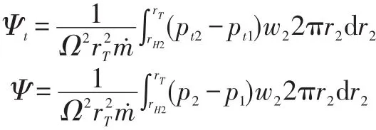
Hence,by mass averaging the pressure changes,the total and static head coefficients are expressed by:
3.4 Tip Clearance Losses
The effects of blade tip clearance and Reynolds scaling on the pumping performance of high-head helical inducers has been characterized in a test campaign conducted in the CPRTF on a three-bladed,tapered-hub,variable-pitch inducer(see Figure 6)named DAPAMITO3.The test inducer,whose main geometrical and operational parameters are reported in Table 1,is made in 7075-T6 aluminum alloy and has been designed in accordance with the indications of the present model.

Fig.6 The DAPAMITO3 inducer without the Plexiglas inlet pipe
The overall dimensions of this inducer have been chosen for easy installation and testing in the current CPRTF configuration.A moderate value of the blade loading(with a diffusion factorD=0.39)and a high solidity(σT=2.03)have been chosen for reducing the leading-edge cavity and improving the suction performance.The value of the tip incidence-to-blade angle ratio α/βb<0.5has been selected with the aim of controlling the danger of surge instabilities at design flow under cavitating conditions.

Tab.1 Geometrical and operational parameters of the DAPAMITO3 inducer.
The tests on the DAPAMITO3 inducer reported in the present paper have been carried out in the Cavitating Pump Rotordynamic Test Facility(CPRTF),specifically designed for characterizing the performance of cavitating/non-cavitating turbopumps in a wide variety of alternative configurations(axial,radial or mixed flow,with or without an inducer;Rapposelli et al.,2002a,2002b;Pace et al.,2012)[33-35].The facility operates in water at temperatures up to 90°C and is intended as a flexible apparatus readily adaptable to conduct experimental investigations on virtually any kind of fluid dynamic phenomena relevant to high performance turbopumps.The test section can be equipped with a rotating dynamometer,for the measurement of the forces and moments acting on the impeller,and with a mechanism for adjusting and rotating the eccentricity of the impeller axis in the range 0÷2 mm and ±3000 rpm.The inlet section,made in Plexiglas,is transparent in order to allow for the optical visualization of the cavitation on the test inducer.It can be easily replaced,allowing for testing inducers with different tip diameters and clearances.
For the present experimental work the facility has been assembled in a simplified configuration without the rotating dynamometer.The inlet pressure and the pressure rise,necessary for the characterization of the pump performance,have been measured by means of an absolute pressure transducer(Druck,model PMP 1 400,0÷1.5 bar,0.25%precision),installed about one inducer diameter upstream of the leading edge cross-section,and a differential pressure transducer(Kulite,model BMD 1P 1 500 100,range 0-6.9 bard,0.1%precision),installed between the inlet and the outlet sections of the test pump(with the low pressure tap at the same location as the absolute pressure tap and the high pressure tap one inducer diameter downstream of the trailing edge crosssection).Two electromagnetic flowmeters(mod.8732C by Fisher-Rosemount,range 0-100 l/s,0.5%precision),mounted on the suction and discharge lines,measure the pump's inlet/outlet flow rates and a resistance thermometer measures the working fluid temperature with±0.5 K precision.
The DAPAMITO3 inducer has been mounted in the CPRTF using a Plexiglas casing designed for providing the same clearance/mean blade height ratio(c%=2.7%)of the reference configuration used for setting the model.Each experimental point has been obtained averaging the differential pressure and flow rate signals acquired for 5 s at 200 sps.The rotational speed and the water temperature have been kept constant at 2 500 rpm(±3 rpm)and 19.2 °C(±1℃)respectively,in order to attain fully-developed turbulent operation(Re=2Ω/v=3.32·106).

Fig.7 Comparison between the experimental and analytically predicted non-cavitating performance of the DAPAMIT0 3 inducer(Ω=2 500rpm,Re=3.32×10⁶).
Figure 7 reports the experimental pumping performance(red stars)compared to the results obtained from the analytical model(blue circles).The close agreement of the two data sets confirms both the predictive capability of the reduced order model and the high-bead nature(Ψ>0.15),as reported in Jakobsen,1971)[1]of the DAP AMITO3 inducer.Efforts have been directed to generalizing the predictions of the analytical model in order to account for clearance variations.As reported in the literature(Brennen,1994)[4],the performance of non-cavitating inducers is relatively insensitive to the clearance forc%<2%and declines rapidly for larger values ofc%.Clearance changes affect both the inducer bead and the flow coefficient,which are modified by the backflow.The relationship between the variations of the bead and flow coefficients can be obtained by assuming that the hydrodynamic nature of the test rig losses is not influenced by changes of the inducer tip clearance,all other operational conditions being the same(see the schematic representation in Figure 8).
Under this assumption,the relation between the bead and the flow coefficients at different clearances becomes:

where the subscripts l and h refer to different clearances, onelower (l) than the other (h). This equation allows for the noncavitatinginducer performance to be scaled for different tipclearances once the associated head change is known. On thebasis of this simple correlation, the model has been modified totake in to account the actual clearance/mean blade height ratio.
Figure 9 reports the effect of tip clearance on the noncavitating performance of an inducer adapted from Brennen,1995[5]:the head coefficient bas been made non-dimensional using the head coefficient(Ψ0)corresponding to a clearance/blade height ratio of 1.12%,where the clearance effect seems to invert its trend.The empirical correlation reported in Figure 9 can be used for estimating the ratio Ψl/Ψhand the previous equation gives the corresponding correction in terms of flow coefficients ratio.
Another series of cold water tests has been carried out on the DAPAMITO3 inducer aimed at experimentally validating the results of the proposed scaling for tip clearance effects.The inducer has been assembled in the CPRTF using a Plexiglas casing designed for providing a blade clearance-tomean height ratio equal to 6.8%,a disproportionately large value sometimes used in the characterization of rotordynamic whirl forces to avoid rotor/stator contact.The non-cavitating performance curves have been obtained with the previous experimental procedure at constant water temperature(19.2±1℃)using three different values of the rotational speed(1 500,2 000 and 2 500 rpm,±3 rpm)in order to verify the Reynolds-independence of the test results.
Figure 10 reports the experimental pumping performance compared to the results predicted by the analytical model scaled for tip clearance effects(blue circles).The results confirm that the characteristic curves are Reynolds-independent,as expected since the flow is fully turbulent(Re>106),and that the inducer head is reduced w.r.t.operation at the reference tip clearance value.The predicted performance curves are almost superposed to the experimental data,thus validating the effectiveness of the proposed method for tip clearance scaling.
3.5 Temperature Effects
The non-cavitating characteristic curve of the DAPAMITO3inducer has been experimentally determined at differentvalues of the temperature of the working fluid. As shown inFigure 11, the non-cavitating performance is affected by thevariation of the water temperature. All tests have been conductedat fully-developed turbulent Reynolds numbers ( Re >106 ),and therefore at flow conditions where turbulence effects areReynolds-independent. In present experiments the only relevantflow property that is significantly influenced by temperatureis the kinematic viscosity, which for water decreases approximatelyby a factor of 3 from 20℃ to 75 ℃.

Fig.8 Schematic representation of two non-cavitating performance curves obtained with different tip clearance values(subscripts h and l refer to high and low clearances)
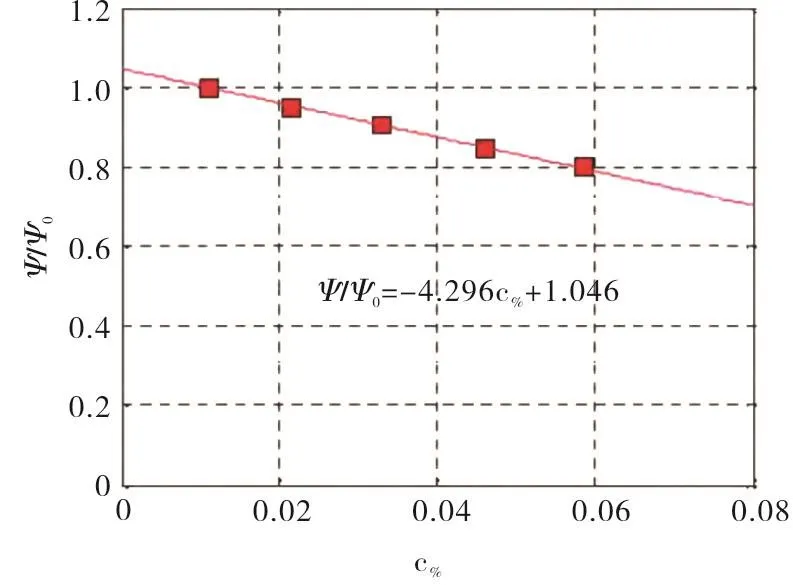
Fig.9 The effect of tip clearance on the non-cavitating performance(adapted from Brennen,1995)[5]

Fig.10 Comparison between the experimental and analytically p redicted non-cavitating performance of the DAPAMITO3 inducer

Fig.11 Non-cavitating performance of the DAPAMITO3 inducer at different water temperatures
The available evidence shows that the performance of the inducer decreases when the temperature of the flow is higher,and therefore its kinematic viscosity is lower.Furthermore,it is worth noting that even in the case of full Reynolds similarity,obtained by adjusting the rotational speeds to attain equal Reynolds numbers in both of the experiments,the characteristic curves obtained at different water temperatures do not overlap(red stars and green circles in Figure 11).On the other hand,two hot tests conducted at the same temperature essentially give the same characteristic curve even if the values of fully-developed turbulent Reynolds numbers are different(pink triangles and green circles in Figure 11).This result is fully consistent with the cold water tests carried out at the same temperature with different rotating speeds,illustrated in Figure 10.
As for the head degradation observed for different tip clearances,the reduction of the pumping performance of the inducer with the flow temperature is evident in the simultaneous decrease of both the head and flow coefficients along the load characteristics of the water loop,as expressed by the previous equation.It appears that the liquid temperature influences the intensity of the tip leakage.Strictly speaking,the temperature,which affects the physical properties of the working fluid,can also slightly modify the geometric similarity of the experiments when the rotor and stator have different thermal expansion coefficients.In particular,the thermal expansion coefficient of the Plexiglas casing is three times larger than that of the aluminum inducer.As a result of a preliminary analysis,this effect is not completely negligible,but it is not by itself sufficient to justify the degradation of the pumping performance experienced in the hot tests.
The available experimental evidence suggests therefore that the observed behavior of the head coefficient is due to the sensitivity of the tip clearance flow to the temperature of the working fluid.Viscous blockage effects reduce the tip leakage flow and their intensity is expected to scale with the tip clearance Reynolds numberReδ=2ΩrTδ/v,whose value is much lower than the value needed to attain Reynolds independence nondimensional inducer performance.Hence,changes of the tip clearance Reynolds number induced by the differential thermal expansion of rotor and stator are expected to affect the nondimensional performance of the inducer even at constant values ofRe=2Ω/vin excess of 106.
Consistently with this interpretation,the results of Figure 12 confirm that the noncavitating performance of the DAPAMITO3 inducer at different flow temperatures is well correlated to the tip clearance Reynolds number computed using the temperature-dependent liquid viscosity,neglecting the small changes of the tip clearance due to rotor/stator differential thermal expansion.The characteristic curve at 19.2℃has been chosen as reference,while the ratio of the head coefficients has been extrapolated from the experimental data with the same scaling equation used for the clearance.In first approximation,the ratio between the head coefficients can be considered approximately linear v/s the tip clearance Reynolds number.The influence of the working fluid and its temperature on the non-cavitating performance is also evident in Yoshida et al.,2005[36],where the same test article has been tested in cold water and in liquid nitrogen.Due to the lower kinematic viscosity of the liquid nitrogen with respect to cold water,the non-cavitating head coefficient at the same flow coefficient is lower in nitrogen than in cold water.

Fig.12 The effect of the tip clearance Reynolds number on the non-cavitating inducer performance.
4 Model Discussion and Validatio n
With reference to the definition of the inducer geometry,in the stated assumptions and approximations the standard requirement for radially uniform axial velocity in the blade channels at design conditions determines the correlation between the axial schedules of the hub radius and blade pitch angle of helical inducers.If,in particular,the hub-to-tip radius ratio is known at the leading and trailing edge sections and the design flow coefficient and leading edge blade angle are assigned,then all of the main geometric features of tapered hub helical inducers can be derived,including the trailing edge pitch angle.Comparison with the geometry of the MK1 and FAST2 space inducers,produced by Avio and tested in the Cavitating Pump Rotordynamic Test Facility(CPRTF),confirms that all of the main design characteristics and the relation between the hub geometry and the blade pitch are almost perfectly predicted by the proposed model.
As an example,Fig.13 shows a three-dimensional drawing of a 4-bladed inducer designed by using the model.The inducer tip radius is 90.9 mm,the hub radius is 57 mm at the inlet and 73 mm at the outlet,the tip blade angle is 8.9 de-grees at the inlet and 20.54 degrees at the outlet,the tip solidity is 1.97 and the design flow coefficient is 0.060.

Fig.13 3D rendering of a four-bladed,tapered-hub,variable-pitch inducer designed according to the proposed model

Tab.2 Geometrical characteristics of the inducers used for validation of the proposed model
With reference to the inducer performance evaluation,it is first worth noticing that the numerical solution of the BVP for the discharge velocity profiles and the corresponding closed form approximation lead to essentially equivalent results,as illustrated by the comparison of the noncavitating pumping characteristics shown Fig.14.Only for significantly low values of the flow coefficient(Φ<0.02),when the slip velocity becomes comparable to the axial velocity,a small difference between the two curves can be observed.
The model has been validated against the experimental performance of six different tapered-hub inducers,whose main characteristics are summarized in Table 2.Information on inducers A,B,C and D comes from the open Japanese literature.The experimental data concerning inducers A and B have been taken from Hashimoto et.al.,1997[37],and refer to two different LOX pumps.The tests of inducer C are documented in Fujii et.al.,2002[38].Finally,inducer D is used in the LE-7A HTP and its experimental performance is reported in Fujii et.al.,2005[39].
Figures 15,16,17 and 18 compare the experimental noncavitating characteristics of the MK1,FAST2,Aand B inducers with the respective predictions of the simplified closed form solution.The head coefficients based on the static and total pressure,with and without losses,are reported,together with the“ideal”pumping performance for perfectly guided flow in the absence of pressure losses and deviation effects.For all of these inducers,the static head rise predicted by the model closely agrees with the experimental results.
For better assessment of these results,it is worth noting that the pressure tap used for the measurement of the static head rise developed by the MK1,FAST2,A and B inducers was located more than two diameters downstream of the blade trailing edge.At this location the flow closely approximates the fully-settled axisymmetric conditions necessary for correct comparison of the experimental data with the model predictions.Conversely,Figs.18 and 19 show that the non-cavitating performance of inducers C and D is evaluated with lower accuracy.Most likely,this situation is related to the different position of the downstream pressure tap,which in this case was located very close to the blade trailing edge.This is clearly inconsistent with the intrinsic nature of the proposed model,whose predictions are specifically derived from consideration of the axisymmetric far-field flow downstream of the inducer.The consequent deviation of the tangential velocity profile from the radial equilibrium introduces a systematic error in the evaluation of the centrifugal effects and,therefore,of the static pressure downstream of the inducer.This is confirmed by the almost linear nature of the measured pumping characteristics of inducers C and D,which is consistent with the expected behavior for nearly uniform distribution of the axial flow velocity at the inducer trailing edge before the establishment of radial equilibrium conditions.
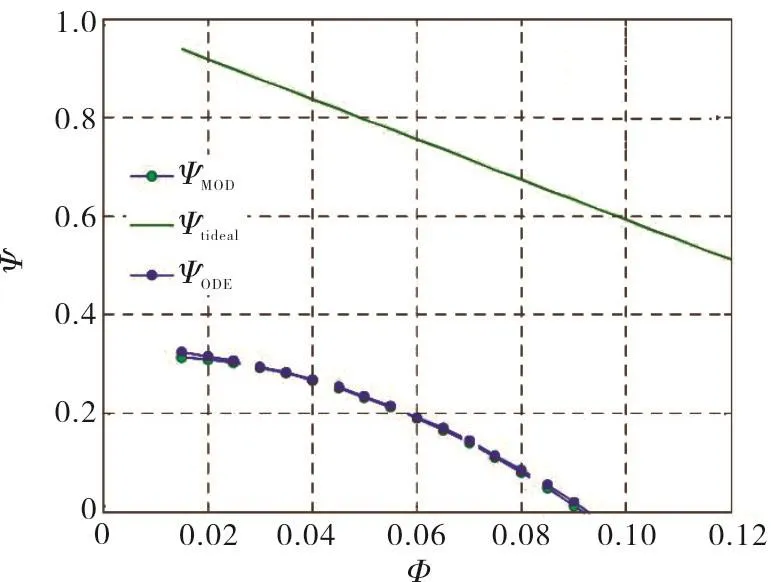
Fig.14 Comparison between the numerical solution(ODE)and the corresponding closed form approximation(MOD)for the noncavitating performance prediction of tapered inducers
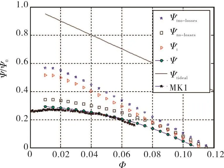
Fig.15 Comparison between the experimental non-cavitating performance of the MK1 inducer(dark stars)and the predictions of the analytical model
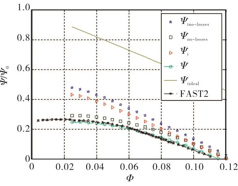
Fig.16 Comparison between the experimental noncavitating performance of the FAST2 inducer(white stars)and the prediction of the analytical model

Fig.17 Comparison between the experimental noncavitating performance of the inducer A(dark stars)and the predictions of the analytical model
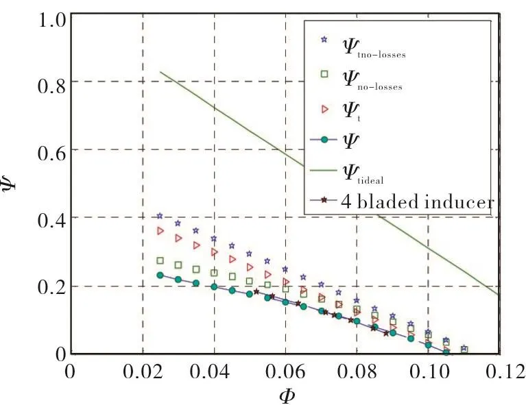
Fig.18 Comparison between the experimental noncavitating performance of the inducer B(dark stars)and the predictions of the analytical model
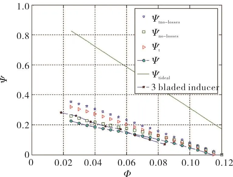
Fig.19 Comparison between the experimental noncavitating performance of the inducer C(dark stars)and the predictions of the analytical model

Fig.20 Comparison between the experimental noncavitating performance of the inducer D(dark stars)and the predictions of the analytical model
The proposed model can also be applied for predicting the performance of helical inducers of more general hub and blade shapes.However,it is obviously expected to deliver best results when used for geometries more closely consistent with the assumptions used for its derivation,as confirmed by the results for the MK1 and FAST2 inducers.
5 Conclusions
Based on the available evidence,the present theoretical model proved to represent a useful tool for preliminary design and performance analyses of turbopump inducers.More specifically,the model is able to provide accurate quantitative indications for geometry definition,3D flow field description,characterization and control of the blade loading,and prediction of the noncavitating pumping characteristics of helical inducers with tapered hub and variable blade pitch angle.
In this context,the model can be effectively used in two ways:
·for the preliminary definition of the geometry of tapered inducers,with particular reference to the hub and blade shape in order to minimize secondary flow losses and attain adequate cavitation performance;
·for the preliminary evaluation of the noncavitating performance of an inducer of given shape,or for defining the main geometric characteristics of an inducer,starting from the desired noncavitating pumping characteristic.
More generally,the model provides inducer designers with a comprehensive interpretative framework where the main-often conflicting-aspects of inducer design and their mutual implications can be assessed,quantified and balanced in view of the attainment of the desired requirements and performance.
The tests on the DAPAMITO3 inducer at different tip clearances and water temperatures indicate that the resulting variation of the inducer performance is generated by the modulation of the tip leakage flow and its response to the variations of the liquid viscosity.They also suggested a semiempirical scaling correction of the inducer head to account for these effects,and confirmed its validity.This correction has been successfully integrated in the model for more accurate prediction of the non-cavitating performance of highhead axial inducers.
The limitations of the model are mostly related to the simplifying assumptions and approximations introduced in order to attain a practical solution.In particular,improvements in the description of the flow,control of the blade load,and accuracy of the inducer performance prediction are expected to be gained by a more refined treatment of viscous effects,capable to account for the axisymmetric nature of the blade boundary layers and the radial changes of their thickness across the inducer annulus.
ACKNOWLEDGEMENTS
The present work has been made possible owing to the continuous support of the European and Italian space agencies over more than two decades.The author would like to acknowledge the invaluable work of his collaborators Fabrizio D'Auria,Emilio Rapposelli,Angelo Cervone,Cristina Bramanti,Lucio Torre,Angelo Pasini,Giovanni Pace,Dario Valentini and Ruzbeh Hadavandi.The author is also especially grateful to Dr.Giorgio Saccoccia,ESA-ESTEC,Nordwijk,The Netherlands,for his constant attention,support and encouragement.Special thanks go to Bella Sparrow and Tina Bomb from GMYS-Space.
