Torsional negative stiffness mechanism by thin strips
2019-07-08JinyouLiKngjiFuYongpengGuZhihuZho
Jinyou Li, Kngji Fu, Yongpeng Gu, Zhihu Zho,*
a School of Aerospace Engineering, Tsinghua University, 100084 Beijing, China
Keywords:Negative stiffness Compliant mechanism Strip Torsional spring Flexible multibody system
A B S T R A C TNegative stiffness mechanisms have great application potential in different fields, such as vibration isolation, energy absorption and mesh antenna unfolding. Although numerous compliant mechanisms with negative stiffness features have been implemented in literature, the designing work remains in its infancy, and proposing an original design strategy may open a new avenue for the future inventions. In this study, inspired by a toy, we developed a novel type of compliant mechanism composed of thin strips, possessing negative stiffness property under torsion. The negative stiffness feature is achieved by large deformation of the strips rather than mechanical buckling. As a consequence, the obtained negative stiffness segment covers a significantly long range. Demonstrated with examples, it was shown that the proposed mechanisms could be combined with other compliant mechanisms to realize long-range unusual torque-angle relationships, which can be used in different applications.
A negative stiffness mechanism offers a decreasing force or torque with the increase of deformation over a certain deflection range. This unusual force-displacement behavior has great application potential. On the one hand, negative stiffness mechanisms can be combined with positive stiffness springs to set up quasi-zero-stiffness mechanisms [1-3], which have been used in broad areas, to name a few, vibration isolation [4-7], nonlinear energy sink [8], energy absorption [9], gravity compensation [10,11], force regulation for protecting fragile objects during manipulation [12]. On the other hand, negative stiffness mechanisms alone are beneficial to some applications. For example, a compound bow [13] has a force-draw curve with negative stiffness,which makes it easy to aim the target at full draw; deployable mesh antennas demand that their unfolding mechanisms output increasing forces with the release of stored energy [14], owning negative stiffness. Besides, the recently emerged study on controlling wave propagation [15, 16] relies heavily on negative stiffness structures. Therefore, designing negative stiffness mechanisms is of great concern.
Negative stiffness mechanisms can be achieved in an active or passive way. The active way requires sensors and sophisticated control systems [17], making it challenging to balance size,cost, reliability, and accuracy. The passive way needs only structures, whose designing principle is mainly based on lumped or distributed compliance [18]. In the lumped compliance designs,rigid bodies are connected by several springs to form a traditional rigid mechanism [19-22], and the negative stiffness feature is achieved by geometric nonlinearity of the mechanism. In the distributed compliance designs, planar straight or curved beams are connected by several rigid links to form a compliant mechanism [23, 24], and the negative stiffness feature comes from the nonlinear deformation of flexible parts. Nowadays, a lot of negative stiffness mechanisms have been proposed and developed with various methods. Among them, few compliant mechanisms are designed based on structural [25] or topological optimization [2], which offers a controllable way to achieve a desired force-displacement curve. However, this method owns a drawback that the obtained structure is usually strange and complex[24]. Except for those, most designs are based on several predefined simple structures, using simple physical rules, such as mechanical buckling [26], to get negative stiffness. Undoubtedly,there remain an infinite number of unknown simple structures that can generate negative stiffness, and unveiling any novel one of them may open a new gate for designing negative stiffness mechanisms.
Recently, we realized that a toy named as “happy twist”,whose structure is pictured in Fig. 1(a), is a compliant mechanism and may be able to output a negative stiffness feature under torsion. The toy is composed of two rigid discs and several thin strips. If the bottom disc is clamped and the top disc is rotated,the center of each strip will gradually approach the rotation axis.Theoretically, the rotation torque should balance the product of the elastic force and the horizontal arm. Therefore, it is expected that this kind of mechanisms owns a negative stiffness performance since the reduced arm may result in a decreased torque even though the deformation is increasing. Driven by curiosity,we did systematical research on the torsional behavior of this strip mechanism. Firstly, it was verified that the mechanism does have negative stiffness feature. Then, a dimensionless analysis was made to quantitatively reveal the relationship between negative stiffness and the geometric parameters. Finally, several examples were demonstrated to show that the strip mechanism can be used to design unusual mechanisms such as quasi-zerostiffness mechanisms.
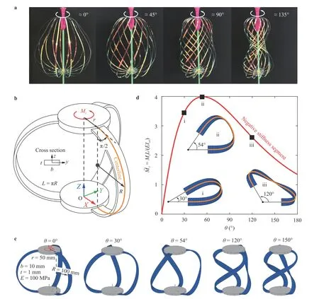
Fig. 1. Compliant mechanisms composed of thin strips.
Figure 1(b) sketches a compliant mechanism made of thin elastic strips. It is a rotational symmetric assembly composed of two rigid discs and several identical flexible strips that are circularly arranged with respect to the Z-axis. The bottom disc is fixed on the ground, and top disc is allowed to rotate but not to translate along the global Z-axis. Each strip is curved and locates within a radial plane. For simplicity and clarity, the illustrated mechanism has three strips, but the number of strips can be arbitrary as long as adjacent strips do not interfere with each other.
A straightforward way to fabricate such a mechanism is bending straight strips and fixing their two ends onto the rigid discs. As a result, each trip in the assembly is pre-stressed into a semicircle shape with a constant curvature, since the strip only suffers from a uniform out-plane bending momentum exerted at the two ends. This study focuses on investigating mechanisms manufactured in this way. For them, the geometry is fully depicted by four parameters shown in Fig. 1(b) - the disc radius r, the radius of the strip centerline R, the width b, and the thickness t of the rectangular cross section. In addition, for the cross section,Iyy= bt3/12 and Izz= tb3/12 are the area moments of inertia related to the two principal axes;is the torsional constant. If t/b << 1,≈ 1/3 and Ixx≈ bt3/3, four times of Iyy.

Rotate the top disc by angle, then all of the strips will undergo complicated but identical flexible deformations. For a single strip, ifgoes larger, experience on the toy suggests that the required torque Mzacted on the top disc is a nonlinear function of. To quantitatively verify this conjecture, a numerical model of the mechanism was built based on our lab's in-house code of flexible multibody dynamics [27, 28]. As shown in Fig.1(c), each strip was uniformly meshed by 100 geometrically-exact beam elements [29, 30], whose initial configuration is a semicircle but the zero-stress configuration is a straight line. Fixing the bottom disc and rotating the top disc were formulated by constraint equations [31, 32]. Torque Mz() was obtained through extracting the rotating reaction torque and dividing it by the number of strips.
With geometrical and mechanical parameters shown in Fig.1(c), the simulated deformations of the elastic strips at five typical rotation angles are illustrated. For the convenience of description, a reference torque was introduced, where is the strip semicircle length and E is Young's modulus of the strip material. And a nondimensionalized torque is defined asThe calculated versus curve is plotted in Fig. 1(d) for ∈ [0, 180°]. Not surprisingly, is a nonlinear function. However, it is interesting to find that this curve has an unusual long-range negative stiffness segment. To understand the underlying mechanism of this phenomenon, a simple explanation is offered in the following paragraph.
Figure 2(a) shows several snapshots of centerline of a single strip from top view, at different rotation angles. For a given angle, divide the strip into two parts along the cross section of the midpoint of the centerline, then planar static analysis implies that the external torque Mzbalances both the internal elastic force fland the torque Mlthat the lower part acted on the upperpart. Use d to denote the horizontal distance from origin to midpoint, then there is

where the symbols with an overline represent their corresponding dimensionless quantities. The distance is nondimensionlized by L, the force by Mref/L and the torques byFigure 2(b) confirms that Eq. (1) is correct, and reveals thatmainly balanced by elastic force for large . Furthermore,Fig. 2(c) illustrates that the force arm continuously decreases with the increase of . This is the root cause of the torque's negative stiffness behavior, as speculated in the previous analysis of the toy.
Since the negative stiffness feature has great potential to get a broad application, a further study was made to understand how the strip parameters affect the torque-angle relationship and the negative stiffness.

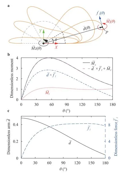
Fig. 2. Nondimensionlized torque analysis of the negative stiffness feature for a single strip.
As shown in Fig. 3(c), for a given R/r, reachmaximum at the turning point , and has a negative stiffness segment from to 180°. Additionally, the slope of the secant line from to 180°, , wasfined here as an approximation of the negative stiffness. Then, both and are functions of R/r only. Fitting the data in Fig. 3(c) yields Fig. 3(d)and

These two equations can be directly used to estimate the maximal torque and negative stiffness for a specific strip.Nevertheless, it is safer to limit its usage on the strips with geometry R/r ∈ [2, 20] and b/t = 10, since the above equations are fitted with data in this parameter region.
It is worth to point out that the above study is based on the strips whose stress-free configuration are straight and are bent into semicircle when assembled into the mechanism. However,these assumptions are not necessary conditions of negative stiffness behavior, so that they are removable. If the strip in the assembly is achieved by bending a straight strip into an arc shape other than semicircle or the stress-free state of the strip is a spatial curve, the corresponding torque-angle relationships may also have negative stiffness features.
Firthermore, this research demonstrates several ways of exploiting strip mechanisms to generate unusual torque-angle relationships. Figure 4 shows three examples, in which all of the torque-angle curves were calculated based on flexible multibody models built in a similar way with the previous verification.
The first example illustrated in Fig. 4(a-b), aims to realize a roughly constant torque within a certain range. The basic idea is that the strip mechanism has a long-range negative stiffness segment, while a helical spring has a positive torsional stiffness.Thus, putting them in parallel, as shown in Fig. 4(a), can produce a quasi-zero-stiffness mechanism. In detail, in Fig. 4(b), the blue dash line shows that the six strips output a total negative stiffness= -7.232 from= 54° to 180° estimated by Equ. 4;the red dash-dot line shows the helical spring's normalized stiffness is= 7.228; the solid black line is their total output. It gives a nearly constant torque as expected. This property has been frequently used in vibration isolation and energy absorption.
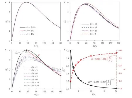
Fig. 3. Parameter analysis of the torque-angle relationship for a single strip.
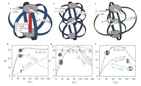
Fig. 4. Synthesized mechanisms with abnormal torque-angle relationship.
The second example is shown in Fig. 4(c). It connects two identical strip mechanisms in series. The elemental strip mechanism is the same as the one used in the first example. Its torque-angle relationship is drawn by blue dash line of Fig. 4(d),and two rotation angles and share a common normalized torque . Thus, in the series mechanism, torque should have three corresponding angles, i.e., , and .However, further stability analysis shows that the branch is unstable since it owns more elastic energy. Therefore, for the series mechanism, the stable path of the torque-angle curve is along the the solid black line. It has the same maximum while the corresponding angle twice of that in the elemental mechanism. Overall, compared with the elemental mechanism, the series mechanism has lower positive stiffness but higher negative stiffness.
The third example schemed in Fig. 4(e), connects the series mechanism of the second example with another outer strip mechanism in parallel, all strips sharing the same cross section.For clarity, the strips in the series mechanism are reduced from six to three, and the corresponding torque becomes half of the torque in the second example. Figure 4(f) shows the torque-angle curve, in which blue dash line belongs to the series mechanism and green dash-dot line belongs to the outer strip mechanism. Their maxima occur at = 108° and = 55°respectively, in which is slightly different from because Ro/rovaries with respect to R/r. The Ro/rovalue of the out-er strip is adjusted to let the total torques atandbe the same. In this way, the final output of the torque-angle relationship forms a reverse U-shaped curve as shown by the solid black line in Fig. 4(f). This type of curve can be used in unfolding mesh antennas.
Inspired by a toy named as “happy twist”, we developed a novel type of torsional negative stiffness mechanism. It is composed of thin strips and belongs to the distributed compliance design category. However, unlike most previous designs, which utilize planar curve beams and/or mechanical buckling to achieve negative stiffness, the current design is based on spatial curved beams and involves no buckling at all. Combing the proposed mechanisms with other compliant mechanisms in parallel or series can achieve abnormal torque-angle relationships for different application purposes. To our best knowledge, the proposed mechanism is a pioneer work on making use of spatial beams, and it is considered as a new path on designing negative stiffness mechanisms.
Acknowledgement
This research was supported by the National Natural Science Foundation of China (11872221 and 11302114) and the Major State Basic Research Development Program (2012CB821203).
杂志排行
Theoretical & Applied Mechanics Letters的其它文章
- Mechanics of Tokamak fusion components
- Delamination strength of HTS tape under transverse tensile stress and its enhancement by using different Ag layer depositing temperatures
- Numerical study of MHD mixed convection under volumetric heat source in vertical square duct with wall effects
- Progress on design and related R&D activities for the water-cooled breeder blanket for CFETR
- Numerical methods for the magneto-mechanical coupling analysis of invessel components in Tokamak devices
- Progress on the ultrasonic testing and laser thermography techniques for NDT of tokamak plasma-facing components
