Numerical methods for the magneto-mechanical coupling analysis of invessel components in Tokamak devices
2019-07-08XudongLiShejuanXieCuixiangPeiZhenmaoChen
Xudong Li, Shejuan Xie, Cuixiang Pei, Zhenmao Chen*
Shaanxi Engineering Research Center of NDT and Structural Integrity Evaluation, State Key Laboratory for Strength and Vibration of Mechanical Structures, Xi'an Jiaotong University, Xi'an 710049, China
Keywords:Magneto-mechanical coupling analysis In-vessel component Plasma disruption Halo current Numerical simulation
A B S T R A C TMagneto-mechanical coupling vibration arises in the in-vessel components of Tokamak devices especially during the plasma disruption. Strong electromagnetic forces cause the structures to vibrate while the motion in turn changes the distribution of the electromagnetic field. To ensure the Tokamak devices operating in a designed state, numerical analysis on the coupling vibration is of great importance. This paper introduces two numerical methods for the magneto-mechanical coupling problems. The coupling term of velocity and magnetic flux density is manipulated in both Eulerian and Lagrangian description, which brings much simplification in numerical implementation. Corresponding numerical codes have been developed and applied to the dynamic simulation of a test module in J-TEXT and the vacuum vessel of HL-2M during plasma disruptions. The results reveal the evident influence of the magnetic stiffness and magnetic damping effects on the vibration behavior of the in-vessel structures. Finally, to deal with the halo current injection problem, a numerical scheme is described and validated which can simulate the distribution of the halo current without complicated manipulations.
The Tokamak is a type of fusion reactor using magnetic fields to confine hot fusion fuel in plasma state. The plasma moves along the toroidal direction at high speed producing a huge current of tens of megampere. At the present stage, this plasma current may become unstable, which will lead to plasma disruptions (PD). During this procedure, both the heat energy and current of the plasma decay rapidly in tens of milliseconds. Changes of the magnetic flux induce large eddy currents in the surrounding in-vessel conductive components and vacuum vessel due to the electromagnetic induction. In recent years, new Tokamak configurations of elongated shapes are widely studied because of their improved confinement characteristics [1]. However, this kind of configuration is more likely to cause another type of plasma disruption, i.e., the vertical displacement event (VDE).The plasma moves in vertical direction and finally impacts to the plasma-facing structures. A halo current up to 50% of the predisruption plasma current on the plasma surface together with a heat flux of tens of megajoule per square meter [2] will hit the invessel components. The halo current as well as the eddy current interact with the plasma confinement magnetic fields giving rise to large electromagnetic (EM) forces. Large thermal stress is also produced by the thermal flux from the core and the joule heat due to eddy currents. These electromagnetic and thermal loads may damage the in-vessel components or vacuum vessel so that the mechanical analysis for the related structures considering the electromagnetic and thermal loads is of great importance for ensuring the safety of Tokamak structures.
The key issue in the mechanical analyses is the coupling effect to the EM field, which implies that the vibration of the structure will perturb the induced EM fields as well as the corresponding EM forces. The additional EM force caused by velocity term affects the vibration characteristics, which are described as the magnetic stiffness effect and magnetic damping effect [3, 4].A lot of attentions have been paid to the magneto-mechanical coupling analysis and its application to Tokamak structures in recent decades. The major difficulty of this problem is the appearance of the velocity termif the problem is formulated in the Eulerian description. Asymmetry arises in the coefficient matrices and numerical divergence may occur. One way to deal with the velocity term is to decompose it into two matrices which contain information of the magnetic stiffness and magnetic damping effect respectively [3, 4]. This approach, however, is not easy to implement owing to the complexities of generating the coefficient matrices of the magnetic stiffness and the magnetic damping. The application of this approach is thus limited to objects with simple geometries such as plates and arches. An alternative approach is to formulate the coefficient matrices from the integral form of the EM equations [5, 6]. This approach has been successfully applied to the magneto-mechanical coupling analysis of international thermonuclear experimental reactor(ITER) structures and obtains a set of interesting results about the magneto-mechanical coupling effects [7]. However, this method also has some limitations from the stand point of numerical efficiency. The integral formulation brings full coefficient matrices of EM field that put high demands on the solver.Besides, auxiliary degrees of freedom (DoFs) are needed if the halo current injection is considered, which worsens the calculation burden.
To overcome the numerical difficulties described above, the authors have proposed two effective schemes for the magnetomechanical coupling analysis. The first method adopts the Lagrangian description of the EM field so that the velocity term vanishes with the help of edge finite element [8, 9]. The second method uses a set of discrete equations to simultaneously formulate both the mechanical and the electromagnetic fields [10].The velocity term is put to the right hand side (RHS) to avoid asymmetry. Because these two methods are described in different coordinate systems, they will be referred as the Lagrangian method and the Eulerian method hereafter. In this paper, the theoretical derivation and numerical implementation of these two methods are described at first. Then, their validations against Team-16 benchmark problem and applications to the coupling analysis for the in-vessel components of the J-TEXT and the HL-2M Tokamaks are given. Finally, a new scheme is introduced for the treatment of the halo current problem.
The governing equations for eddy current problems of a moving body expressed by magnetic vector potential A and electric scalar potential φ are as follows [11]

where v and B are the velocity and magnetic flux density;andare the conductivity and permeability;is the source current density. The velocity term can be expanded as

In Lagrangian description, physical quantities are functions of the material coordinate system and time. The material time derivative is the combination of the spatial time derivative and a convective term [12]

Substituting Eqs. (3) and (4) into Eqs. (1) and (2) and introducing a new scalar potentialyield the governing equations of eddy current problem in the Lagrangian description as

If Eqs. (5) and (6) are discretized using the edge finite element,the velocity term can be eliminated [8, 11]

Figure 1 shows the numerical implementation of the Lagrangian method for magneto-mechanical coupling problems.Considering that the current quench is always accompanied with the thermal quench during disruption, the temperature field analysis is also included to take account of the influence of the thermal load on the in-vessel structures. At the beginning of each time step, coefficient matrices of EM field are reformed based on the morphed mesh and the conductivity modified according to the temperature field at the time instant. Secondly,solve the EM field and transfer the Joule heat and EM force to the temperature and displacement field respectively as excitations.Thirdly, solve the temperature field and transfer the thermal load to the displacement field. Fourthly, reform the matrices of displacement field based on the elastic modulus perturbed by the temperature. Finally, solve the displacement field and morph the mesh of the EM field. This staggered solving procedure of each field is implemented on ANSYS Parametric Design Language (APDL) platform and Solid236, Solid90, and Solid95 elements are used for electromagnetic, temperature and displacement fields respectively.

Fig. 1. Flowchart of the Lagrangian method.
As mentioned above, the appearance of the velocity term produces asymmetry in the coefficient matrices of EM field in the Eulerian description. The computational burden is greatly enlarged and even numerical divergence will be encountered. If we use the velocity and magnetic flux density of the last time step to make an approximation, the cross product term in Eqs.(1) and (2) can be put to the RHS

then the coefficient matrices will keep symmetrical. The treatment of approximating the coupling term with the results of the last time step is called the weak or loose coupling [15]. Such a weak coupling sacrifices a certain numerical precision but gains much simplicity of the numerical implementation. The discretizing coefficient matrices remain unchanged compared to the eddy current analysis of static objects, which follows
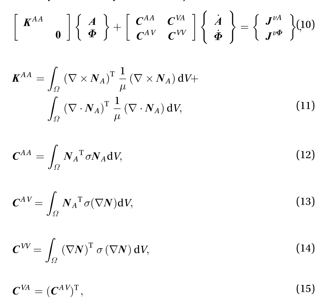
where NAand N are the vector and scalar forms of nodal interpolation shape function;is the time integral of the scalar potential. RHS has the form of


The remaining displacement and temperature fields can be discretized in a conventional way and the staggered solving strategy illustrated before can also be adopted to couple these three fields. However, noticing that the meshes in Eulerian description remain unchanged through out the analysis procedure,it is advantageous to form a global system of equations that covers the three fields. In other words, the equations for electromagnetic, temperature and displacement fields are solved simultaneously at each time step. The solving process and transfers of loads and material parameters only need to be executed once in a single time step, which significantly simplifies the code implementation. Such coupling scheme is named as direct coupling.The global discrete equations are of the following form
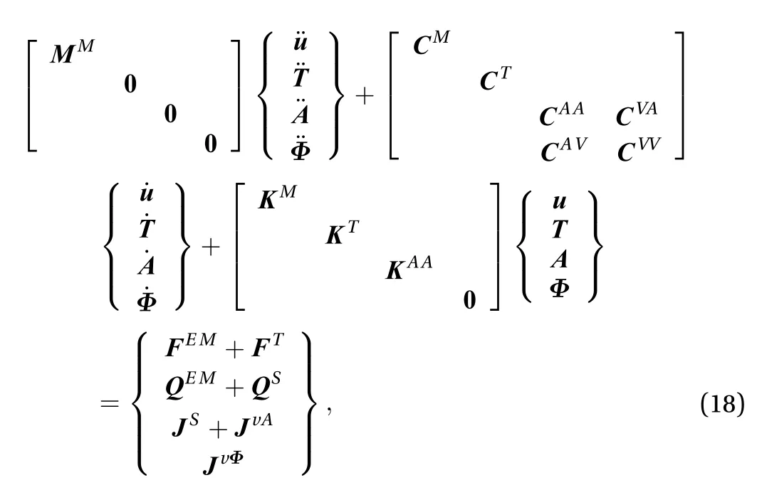
where u and T are DoFs of displacement and temperature; MM,CM, KM, CT, and KTare corresponding coefficient matrices; FEM,FTare the EM force and thermal load; QEM, QSare the Joule heat and heat flux; JSis the source current excitation.
Based on Eq. (18), a direct coupling element considering the magneto-mechanical coupling and the thermal effect has been developed by authors on the user programmable features (UPFs)platform of ANSYS [10]. The information of the coefficient matrices and RHS is stored in the subroutine named UserElme.F provided by ANSYS. The direct coupling element can be invoked as a regular element by APDL providing much convenience. At each time step, the global coefficient matrices are updated according to the material parameters modified by the temperature field, and the RHSs are generated based on the results of the last time step. Dofs of the three fields can be calculated directly so that the iteration between different fields can be avoided.
Team-16 benchmark problem is adopted to validate the magneto-mechanical coupling analysis methods [16]. A copper plate of 115 mm×40 mm×0.3 mm size with its bottom constrained 10 mm is put in a static uniform magnetic field in y-direction. Its mass density, conductivity, Young's modulus, and Poisson's ratio are 8912 kg/m3, 5.81×10⁷S/m, 1.1×10¹¹Pa, and 0.34, respectively. A 27-turn current carrying coil placed above the plate induces eddy currents in the plate and causes it to vibrate torsionally. The inner and outer diameters, height and liftoff distance of the coil are 20.0, 22.0, 24.2, and 9.5 mm, respectively. The coil current is I = 800[exp(-500t)-exp(-6000t)].
To simulate this problem numerically, the plate was discretized into 184 finite elements. The uniform external magnetic field was applied by a set of Helmholtz coils in the Lagrangian method while in the Eulerian method it was accomplished by defining the real constants of the user element owing to the flexibility of UPFs. The displacement of point B (108.0 mm, -7.5 mm,0.15 mm) was traced during vibration. The coupling results when external flux density is 0.3 T are shown in Fig. 2, together with the experimental result and non-coupling result. The good agreement between the coupling and the experimental results gives validations of the Lagrangian and Eulerian methods. Besides, as compared to the non-coupling result, the magnetic stiffness and magnetic damping effects can be observed evidently.
A test module is designed and installed in the J-TEXT Tokamak to measure the EM force and heat flux acting on the in-vessel components during plasma disruption [17]. The coupling numerical analysis is an effective approach to assess the influence of the electromagnetic and thermal loads on the test module.Besides, it can be helpful to establish a reference database for the design and manufacture of the blanket modules of the future Tokamaks such as the tritium breeding blanket.
To simulate the coupling vibration of the test module, a half model of the J-TEXT Tokamak was set up as shown in Fig. 3. The plasma current was simplified as a series of filamentary currents and the current data came from the Tokamak simulation code(TSC) for conditions of the pulse no. 1043861. The Lagrangian method was adopted in this analysis and the detailed procedure can be found in Ref. [18]. An important improvement was made in this paper that the material of the test module has been changed to the reduced activation ferritic and martensitic(RAFM) steel. Besides, the iron core was also taken into consideration.
As shown in Fig. 4, EM forces are generated in the two side walls by the interaction of the toroidal magnetic field and the eddy currents around the module walls. The coupling of the EM forces forms a torque that causes a torsional vibration of the test module around the supporting rod. Figure 5 shows its torsionally deformed shape at 5 ms time instant.
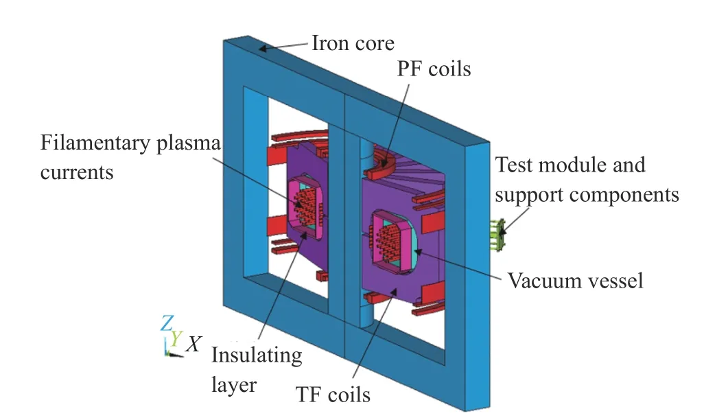
Fig. 3. Numerical model of the J-TEXT Tokamak (PF: poloidal field,TF: toroidal field).
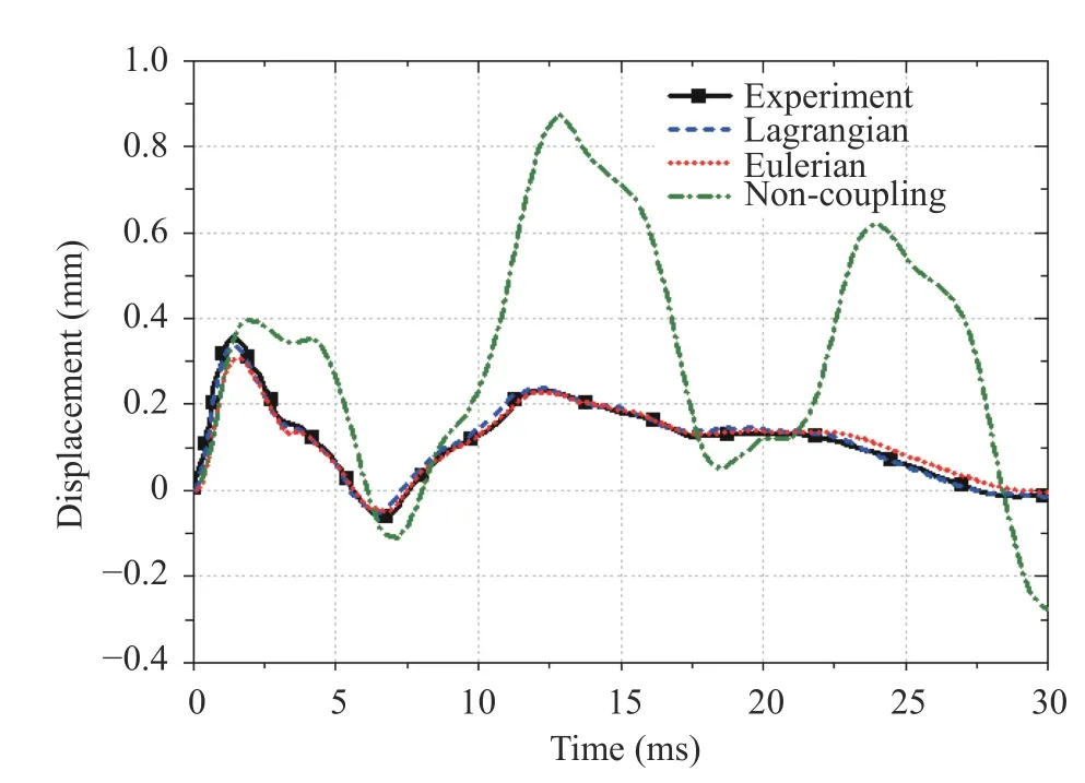
Fig. 2. Displace of point B when By = 0.3 T.
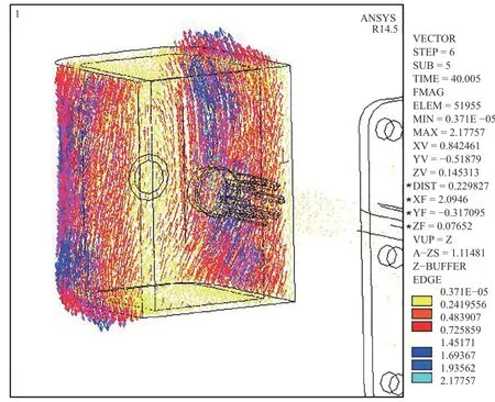
Fig. 4. EM forces acting on the test module at 5 ms.
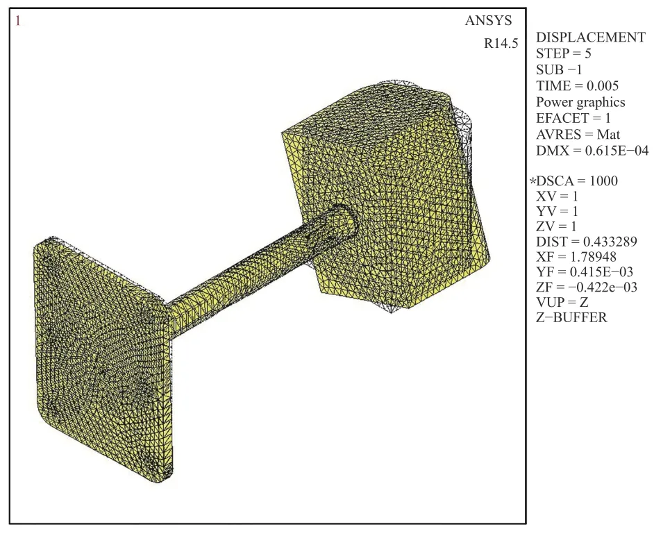
Fig. 5. Deformation of the test module at 5 ms.
During vibration, the stress state in the module varies periodically. The maximum stress arises at the slots of the supporting rod owing to the stress concentration. In Fig. 6, the time evolution of the first principle stress at the element with the maximum stress is plotted. The maximum value is around 151 MPa,twice of the case where the test module is made of 316L steel[18]. The stress reaches the maximum value at 12 ms and then attenuates rapidly. Since the structural damping was not defined in the analysis, this attenuation is caused by the magnetic damping. The influence of the magnetic damping effect on other Tokamak structures has also been investigated. A recent research reported that the displacement of ITER structures was reduced of about 10% taking account of the coupling effect [7].Therefore, the magneto-mechanical coupling analysis is necessary for the accurate assessment of in-vessel components.
HL-2M Tokamak under construction in Southwestern Institute of Physics (SWIP) is an upgrade of HL-2A [19]. The plasma current and the auxiliary heating power are increased to study the plasma physics in high parameters. The in-vessel components will suffer stronger EM and thermal loads hence the coupling analysis is needed to ensure the safety of the Tokamak structures during disruption.
The conductive vacuum vessel is adopted in this research since it is the major force-supporting component in Tokamak. A 5-degree simplified model of the D-shaped vacuum vessel has been established in Ref. [10] as shown in Fig. 7. The Eulerian method is applied to this analysis so that the toroidal magnetic field can be imposed directly. The data of the pulse plasma current and heat flux was selected based on the design parameters of the HL-2M Tokamak. In detail, the peak value of the plasma current was set to be 2.5 MA and decayed to zero in 20 ms,whereas the peak value of the heat flux was set to be 500 MW/m2and decayed to zero in 8 ms.
During vibration, the displacement at the bottom of the vacuum vessel is the largest since this part suffers strong EM and thermal loads. Its time evolution is plotted in Fig. 8 compared to the results without considering the magneto-mechanical coupling effect. It is evident that the period gets longer and the amplitude attenuates when the coupling effect is considered. In other words, the magnetic stiffness effect and the magnetic damping effect influence the vibration behavior of the vacuum vessel significantly during a fast disruption process. In future tokamaks with high parameters such as ITER and China fusion engineering test reactor (CFETR), in-vessel structures serve in higher temperature, stronger plasma current and confining magnetic field. The coupling effect may play a more significant role hence needs continuous and more careful attention.
During the VDE, a so called halo current is induced on the plasma surface due to changes in the magnetic flux. The magnitude of the halo current varies from 10% to 50% of the pre-disruption plasma current. When the closed flux surface contacts the plasma-facing structures, halo current will flow into the invessel components mainly in poloidal direction. Interaction between the halo current and the toroidal confining magnetic field causes EM forces perpendicular to the current circuit. Detailed investigations of the experimental data show that the toroidal distribution of the poloidal halo current is non-uniform.Corresponding asymmetric EM forces produce high horizontal reaction forces on the Tokamak supporting structures [20].Therefore, the halo currents are important loads to be modeled in the magneto-mechanical coupling analysis.
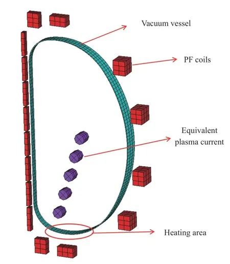
Fig. 7. 5-degree model of the HL-2M vacuum vessel.
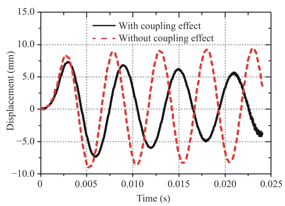
Fig. 8. Displacements at the bottom of the vacuum vessel with and without considering the coupling effect.
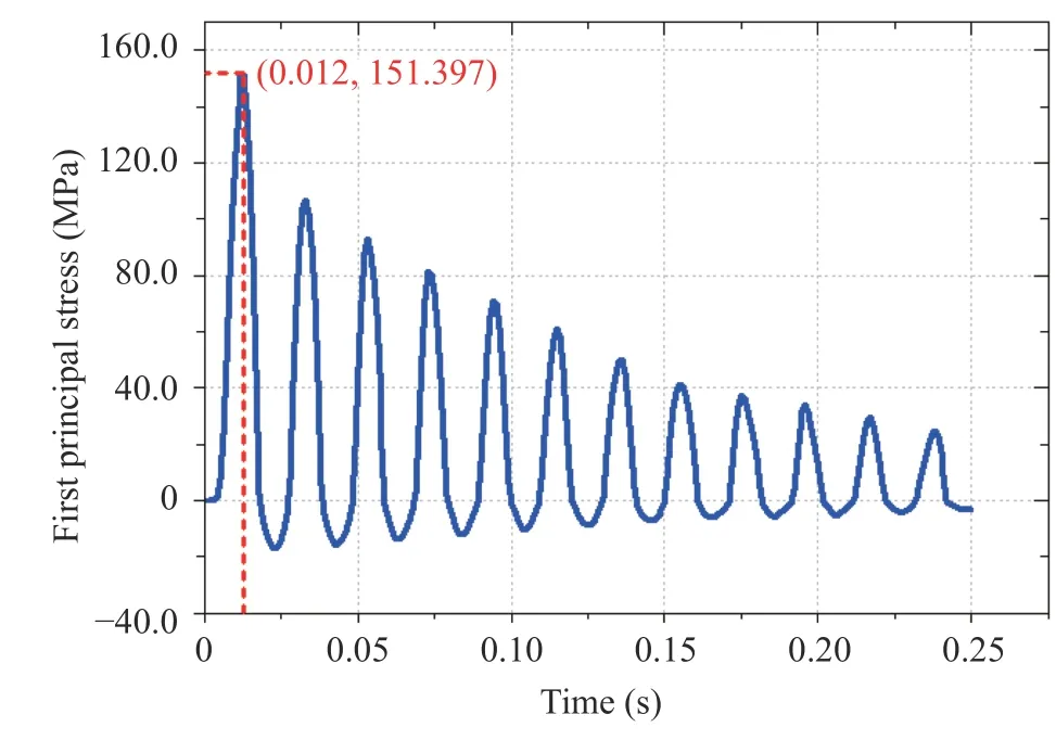
Fig. 6. Time evolution of the first principle stress.
The simulation of halo currents is a field-circuit coupling problem. Normally, some additional DoFs are employed to take account of the circuit part, which enlarges the complexity of the numerical implementation. To model the halo current injection in a relatively easy way, the authors have proposed a solution by introducing a set of current boundary conditions to the governing equations of eddy currents [21]. During the discretization process of the current continuity equation, there presents a surface integral as

Normally this integral is zero because the current has no perpendicular components to the conductor surface. However, in halo current problems, there exist interactions between the halo current on the plasma surface and that in the structures. At each nodes within the interacting region, therefore

The above numerical scheme has been applied to the halo current analysis in the vacuum vessel of HL-2M as reported in Ref. [21]. Figure 9 shows the distribution of halo current in a simplified quarter vacuum vessel model during a typical downward VDE. It is evident that the majority of the current distributes within the areas where the plasma contacts the inner wall. The magneto-mechanical coupling analysis with consideration of the halo current will be carried out in our future works.
In this paper, the methods for magneto-mechanical coupling analysis are introduced for the in-vessel components and VV in Tokamak devices during plasma disruptions. The equation derivation and the numerical implementation of the Lagrangian and Eulerian approach are described for the treatment of the velocity term and coupling dynamic response. Applications of the numerical methods and codes to the dynamic analysis of a test module in the J-TEXT and the VV in HL-2M Tokamak during disruption reveal that the magneto-mechanical coupling effects have evident influence on the vibration of the in-vessel structures. Finally, a numerical scheme to simulate the distribution of halo currents is introduced, providing a convenient approach to deal with the halo current injections during VDEs.
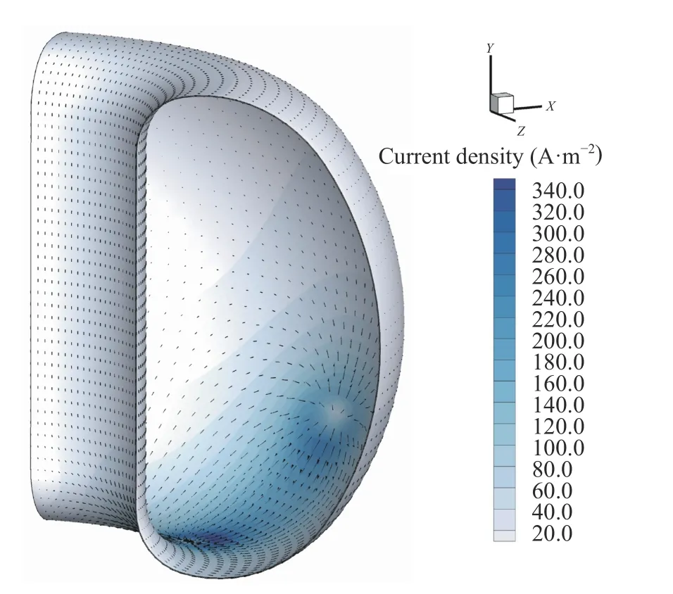
Fig. 9. Distribution of the halo current in a simplified vacuum vessel model of HL-2M.
Acknowledgments
The authors would like to thank the National Magnetic Confinement Fusion Program of China (Grant 2013GB113005) and the National Natural Science Foundation of China (Grants 51577139 and 51407132) for funding in part.
杂志排行
Theoretical & Applied Mechanics Letters的其它文章
- Mechanics of Tokamak fusion components
- Delamination strength of HTS tape under transverse tensile stress and its enhancement by using different Ag layer depositing temperatures
- Numerical study of MHD mixed convection under volumetric heat source in vertical square duct with wall effects
- Progress on design and related R&D activities for the water-cooled breeder blanket for CFETR
- Progress on the ultrasonic testing and laser thermography techniques for NDT of tokamak plasma-facing components
- Considering for the blanket structure scheme of HCCB DEMO
