Progress on the ultrasonic testing and laser thermography techniques for NDT of tokamak plasma-facing components
2019-07-08CuixiangPeiHaochenLiuJinxingQiuTianhaoLiuZhenmaoChen
Cuixiang Pei, Haochen Liu, Jinxing Qiu, Tianhao Liu, Zhenmao Chen*
Shaanxi Engineering Research Center of NDT and Structural Integrity Evaluation, State Key Laboratory for Strength and Vibration of Mechanical Structures, Xi'an Jiaotong University, Xi'an 710049, China
Keywords:Plasma-facing components Ultrasonic testing Laser thermography Delamination Surface crack
A B S T R A C TDuring manufacturing and operation, different kinds of defects, e.g., delamination or surface cracks, may be generated in the plasma-facing components (PFCs) of a Tokamak device. To ensure the safety of the PFCs, various kinds of nondestructive testing (NDT) techniques are needed for different defect and failure mode. This paper gives a review of the recently developed ultrasonic testing (UT) and laser thermography methods for inspection of the delamination and surface cracks in PFCs. For monoblock W/Cu PFCs of divertor, the bonding quality at both W-Cu and Cu-CuCrZr interfaces was qualified by using UT with a focus probe during manufacturing. A noncontact, coupling-free and flexible ultrasonic scanning testing system with use of an electromagnetic acoustic transducer and a robotic inspection manipulator was introduced then for the in-vessel inspection of delamination defect in first wall (FW). A laser infrared thermography testing method is highlighted for the on-line inspection of delamination defect in FW through the vacuum vessel window of the Tokamak reactor. Finally, a new laser spot thermography method using laser spot array source was described for the online inspection of the surface cracks in FW.
One of the main challenges to be overcome for next generation of fusion reactor is the confinement of particles and energy in the plasma. The confinement of the fusion machines such as Tokamak device in current stage is not perfect that the particles and heat may diffuse during operation. Therefore, special plasma facing components (PFCs) are necessary to cool the devices actively [1]. With the help of the PFCs, the particle irradiation and thermal shock on the vacuum vessel (VV) structure,diagnostic probes and modules of injection power can be mitigated. Pressurized water circulates in these components to evacuate the heat through the conducting structure which is usually made of copper alloy. Fabrication of these components substitutes a number of challenging tasks relating to material issue in respect to welding joints of specific bimetallic and trimetallic compounds [2, 3]. To ensure safe operation of these components in fusion reactors, nondestructive inspections of their manufacturing quality is of great importance. In addition, the structural integrity as well as the service life of the PFCs are badly affected by the high heat flux (HHF). Suitable non-destructive testing (NDT) techniques are also in great need to assess the status of the structures.
Thera are many NDT techniques that may be used for the NDT of the PFCs. The selection of these testing approaches relies on many factors, such as the material to be tested, structure or shape of the target PFCs and inspection environment. The monoblock type geometry is the key design for PFCs of the divertor, which essentially consist of armor blocks. Each monoblock is made of Tungsten (W) block with a hole at its center and a cooling pipe of copper alloy (CuCrZr). The pipe is inserted into the hole and joined to the W block using different welding technologies [4]. The joint quality between the W/Cu components is very important for the cooling system, as a defect such as the delamination may leads serious thermal stress and causes damages. Since the ultrasonic testing (UT) earns a good detection ability, it is often adopted for the inspection of the metal/metal joints. Several researches [5-7] have been reported on the development and application of C-scan UT for monoblock Cu-W joints with a small focused probe in the process of fabrication and after HHF thermal fatigue testing. It was reported that the bonding quality of the monoblock Cu-W PFCs can be detected by the water immersion ultrasonic testing technique. A typical study on the ultraonic testing of the upper divertor of experimental advanced superconducting Tokamak (EAST) will be emphasized in Ref. [5].
In the blanket modules, the PFC of first wall (FW) panel is the main components providing shielding from the irradiation and thermal shock during operation for the VV and the ex-vessel systems such as the poloidal field (PF) coils and toroidal field (TF)coil system. The FW panel comprises multilayered plate of three metallic materials (usually beryllium, copper, stainless steel)which are bonded together using the hot isostatic pressure (HIP)welding technique. During operation, the HHF and plasma particles may damage the FW, induce cracks on the surface or at the bonding interface of the FW panel. Therefore, the NDT of the FW is of great importance for ensuring the integrity of fusion reactors. Though the UT techniuqe is one of the most widely used NDT tools for the interface quality control, however, its inspection procedure is complex and the inspection speed is limited as the conventional UT needs liquid couplant between the transducer and inspection targets, Besides, the use of liquid couplant would also pollute the vacuum vessel. To achieve a better inspection for the maintenance of the FW in future Tokamak devices, a noncontact and coupling-free UT method is needed.The electromagnetic transducer (EMAT) technique is a kind of UT based on the electromagnetic mechanisms which directly generate and receive ultrasonic waves in the testing objects[8-10], and can realize a noncontact and coupling-free inspection. This paper highlights the study of the EMAT technique for the in-vessel inspection of delamination defect in the FW through combination of EMAT to the remote handling inspection manipulator.
In addition to the UT techniques, the infrared thermography testing (IRT) is a subject of high scientific interests because of its feature of remote inspection and high detection efficiency[12-14]. Some IRT researches for NDT of the plasma facing components have been down in recent years. Many attention has been payed to the off-line inspection of the monoblocks of divertors but not to the online inspection [15-18]. In this paper, the online inspection of the FW blankets by using laser infrared thermography testing (LIRT) is introduced [19]. On the other hand,the conventional LIRT techniques cannot be applied to the detection of the surface breaking crack, as it grows predominantly perpendicular to the material surface. The needs for the inspection of the surface crack with high sensitivity can be fulfilled by the laser spot thermography (LST). The heat source of the LST technique is a group of highly localized laser spot and the infrared camera is used to detect the distribution of the temperature field. However, there are some difficulties applying conventional LST to a large structures such as the FW as the inspection takes too long time when using point source scanning. In order to improve the inspection efficiency, and to simplify the measurement system and the procedure of data processing, a new LST method for the surface crack measurement in the FW using laser spot array source developed by authors is reviewed in this paper [20]. As the laser array spot thermography (LAST) is a fully non-contact and remote non-destructive technique, it is very promising for the online inspection of the FW at high temperature. Therefore, the study for feasibility of the LAST method to inspect surface crack at elevated temperature is also introduced here.
In EAST, the upper divertor has been upgraded to the actively cooled W/Cu PFCs. There are two types of the new PFCs in the new divertor structure, i.e., the international thermonuclear experimental reactor (ITER)-like monoblock W/Cu units and the flat-type W/Cu units. The former is used in the vertical target regions whereas the latter at the baffle and the dome regions. During the operation of EAST, both the thermal and mechanical loads of high magnitude strike on these components and failure may occur in the W armor, the pure copper interlayer and the heat sink materials, which will result in severe damage to the device. To ensure EAST in a safe state, the NDT is necessary and has been studied in Ref. [5] with UT.
In EAST, the upper divertor is made up with 80 cassettes.Each cassette has two major parts, i.e., the W/Cu-PFCs and 316L cassette body. The former one comprises 9 W/Cu monoblocks(VT: vertical target) and 3 flat-type mock-ups (baffle and dome).The W/Cu-monoblocks are of around 200 mm length and fabricated in two steps. The first step is the joining between the W block and an interlayer of pure copper. The second step is the bonding between the monoblocks and a heat sink tube of CuCrZr material. The bonding procedures are conducted using the HIP technology. The thickness of the interlayer, the length,curvature radius, inner and outer diameters of the tube are 1 mm, 200 mm, 185 mm, 12 mm and 15 mm respectively. In the inspection process of the W/Cu monoblocks, the UT probe can only be inserted into the curved CuCrZr tube since the outer shape of the mock-ups is too complicated.
To fit with the curved shape of the monoblock, a special scanning scheme was designed. The focus UT probe was drove by a flexible tube in the longitudinal direction. The scanning process was stepped in the circumferential direction. Based on this scheme, a spiral UT system was set up to detect the bonding quality of the monoblocks. The testing frequency was chosen to be 15 MHz. For the evaluation of detection effect of the UT, a standard test-piece was fabricated using HIP shown in Fig. 1(a).A series of flat-bottom holes of 1 mm size were fabricated in the sample but other conditions kept the same as the actual product manufacture. A C-scan image of the standard test-piece is shown in Fig. 1(b). It can be seen that though there is normal response caused by the interface effect of different materials, the signal of the flat-bottom holes is clear. For the judgement of the defect, the calibration was conducted. In detail, the amplitude due to the hole whose size is larger than 2 mm was selected as the critical value and set to be 80% of the screen high. The signal exceeding this value will be recognized as a defect signal. The monoblock qualified by the spiral ultrasonic system was then tested through the HHF testing. It is found that the qualified monoblocks can withstood 1000 cycles of heat load at 10 MW/m2. It is also clarified that the bonding quality of W/Cu monoblock PFCs can be properly tested by the proposed UT system [5].
Until now the conventional UT method has been studied and applied for delamination defect inspection in many areas.However, the inspection procedure is complex and the speed is limited for the conventional UT method, as the transducer need to contact to the specimen with liquid coupling. In addition, the liquid couplant may also pollute the VV. A noncontact and coupling-free UT method is desired for the in-vessel inspection of FW. As a noncontact and coupling-free ultrasonic transducer [9,10], EMAT is particularly useful for the automated and highspeed inspection, and in hot, clean, or dry environments. The combination of EMAT with the robotic and remote handling inspection manipulator for the in-vessel inspection of delamination defect in the FW has been developed [11].
The robot-based flexible EMAT inspection system is shown in Fig. 2. The details of the experimental system and the basic principle of the testing method have been given in Ref. [11]. The EMAT is excited by a long burst current to generate a series of ultrasonic waves with a specific central frequency. When there is a delamination defect under the EMAT, an ultrasonic resonance would occurs [11, 21]. A signal processing method based on power spectrum density (PSD) analysis of the resonant ultrasonic signals is introduced for the delamination defects identification and imaging.
Figure 3 shows examples of the ultrasonic C-scan images of a specimen with four artificial delamination defects by using the flexible EMAT system. The images are obtained by measuring the peak values of the PSD curves of the ultrasonic resonance signals at each scanning points. The specimen is made with an aluminum plate and a copper plate bonded together by using diffusion welding. It can be seen that the four delamination defects with size from 5 mm×5 mm to 20 mm×20 mm are clearly identified. The size of the delamination defect can also be directivity evaluated from the image with a relative small error.
Considering the special structure and environment in the VV, carrying out the inspection through the VV window is one of the prefer approaches. To evaluate the feasibility to inspect FW by using LIRT system set outside the VV, the influences of the distance and angles between target FW plates and the inspection system are necessary to be considered. Figure 4 shows the setup of LIRT experimental setup to simulate the online inspection of FW in VV. The exciting laser was generated by the laser driver. A function generator is adopted to provide a square pulse wave to the laser generator module and to modulate the laser duration and power. As the initial laser is in a round shape with Gauss distribution, a set of optical lens is adopted to shape the laser into a relative homogenous round laser spot. In addition, a 95% infrared (IR)-transmittance glass window was fabricated and set in front of the IR camera to take into account the influence of the practical VV window. A multiple angle specimen fixture was fabricated to adjust the distances and angles of FW specimen. Excepting the laser generator and controlling unit, the other sub-systems are set into a dark room cover. A mid-wave infrared camera is adopted to capture the thermal images and to transfer them to computer. During a heating and cooling period,the thermal images were acquired from the end of the laser pulse with 60 Hz frame rate. After 20 s totally 1200 images were recorded to ensure enough transient decay temperature signals[19, 22].
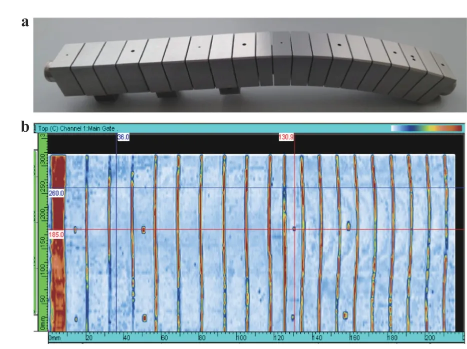
Fig. 1. a Monoblock W/Cu mock-up with flat-bottom holes and b UT C-scan image at the interface of Cu-CuCrZr.
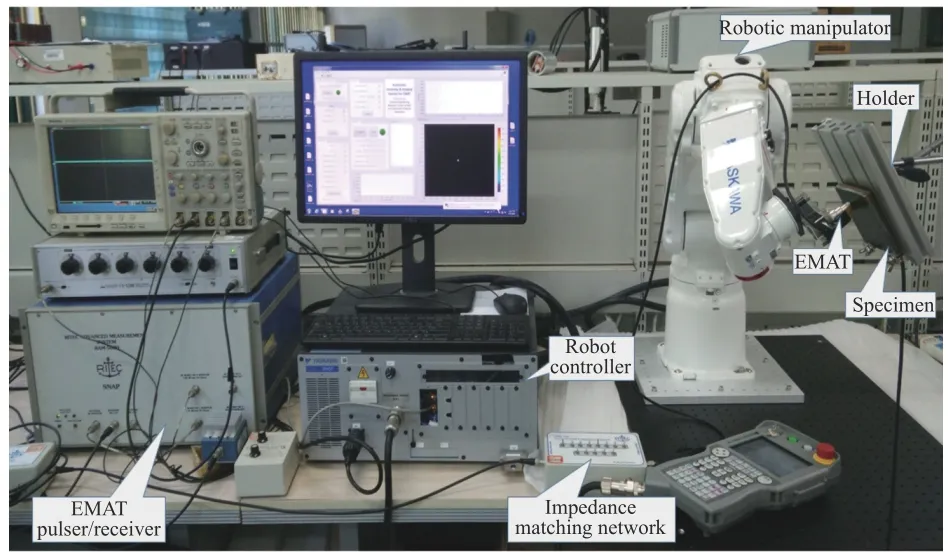
Fig. 2. Setup of the flexible robotic EMAT-scanning experiment system for FW inspection
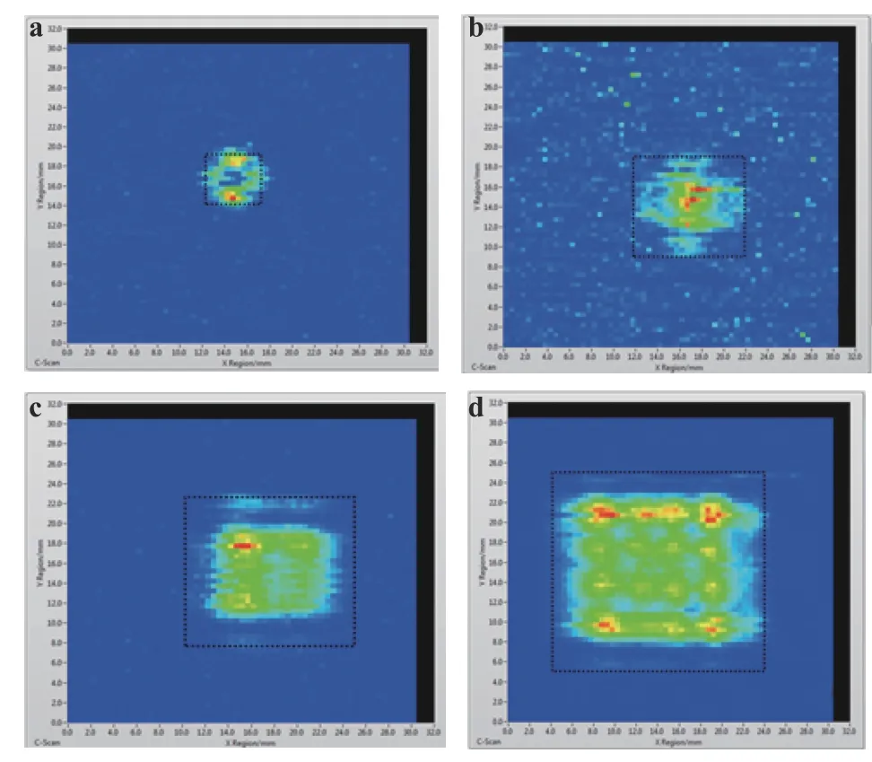
Fig. 3. C-scan images of the different delamination defects:a 5 mm×5 mm, b 10 mm×10 mm, c 15 mm×15 mm, and d 20 mm×20 mm delamination
At first, the direct facing mode inspection is implemented. A calibration experiment is then carried out based on the measured results. The sound reference experiments are carried out with the Al-Cu double-layered specimen. The specimen used here is the same with that mentioned before. After recording the raw thermal images, a Thermographic Signal Reconstruction method (TSR) is applied to reduce noise interference and enhance the quality of the inspection image of laser thermography for a higher defect contrast. As illustrated in Fig. 5, the defects contrast was significantly enhanced by taking difference between calibration and sound reference images. The two defects (with size of 20 mm×20 mm and 15 mm×15 mm, respectively) become clearly visible in this case. However, the size of the defects image seems smaller than their actual size.
To further investigate the performance of this method in practical FW environment, other two inspection modes with different distance and injection angles were also conducted. For further defect contrast enhancement, a defect boundary extracting algorithm was applied to identify the boundary of the defects by using the actual calibration data fork. Figures 6 and 7 show the results of the Al-Cu specimen in the 2.2 m/60°-44° and 2.2 m/35°-44° inspection modes. From these figures it can be noted that the identified defect shapes were transformed and the defect boundary become indistinct with the increasing of inspection angle. The reason is supposed that the IR camera acquired less infrared emissivity in angle modes than in direct facing mode. The 5 mm×5 mm square delamination in the Al-Cu specimen become invisible in these angle modes, which means the detectability in two angle inspection modes are limited at 2.0 depth to width ratio [19].
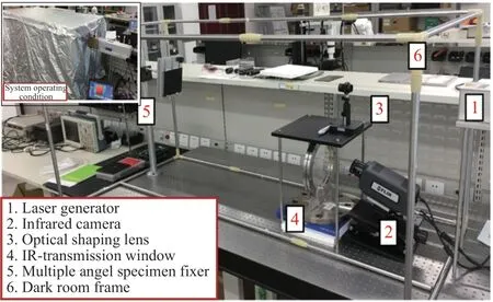
Fig. 4. Setup of LIRT experiment system to simulate the online inspection of FW in VV
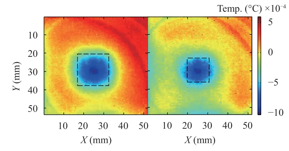
Fig. 5. Processed thermal images of calibration cases
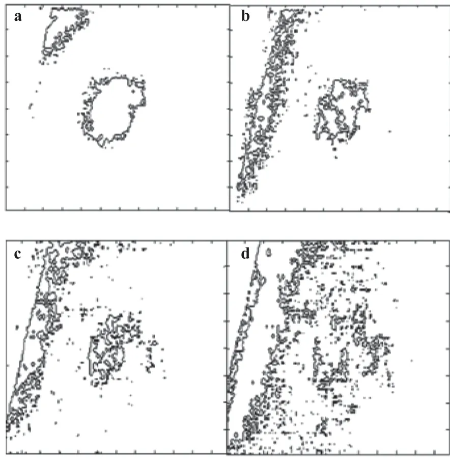
Fig. 6. Defect boundary results of the Al-Cu specimen in 2.2 m/60°-44° angle inspection mode, the size of the four delamination defects are a 20 mm×20 mm, b 15 mm×15 mm, c 10 mm×10 mm,and d 5 mm×5 mm, respectively
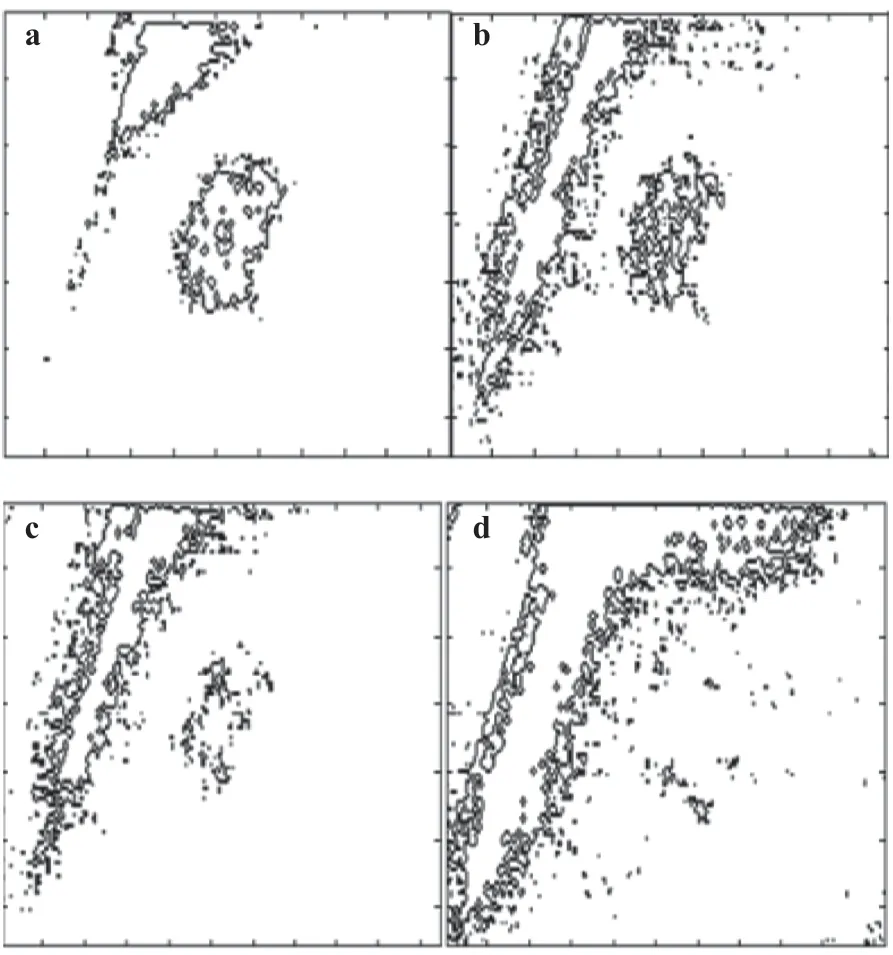
Fig. 7. Defect boundary results of the Al-Cu specimen in 2.5 m/35°-44° angle inspection mode, the size of the four delamination defects are a 20 mm×20 mm, b 15 mm×15 mm, c 10 mm×10 mm,and d 5 mm×5 mm, respectively
In order to improve the inspection efficiency and simplify the testing system, the fiber-guided LAST method has been studied in Ref. [20].
As shown in Fig. 8, the proposed fiber-guided LAST system is composed of excitation, sensing, data processing and control units. Similar to the LST system established before, a function generator is used to modulate the laser duration and power. The modulated laser is firstly coupled into a fiber with a core diameter of 0.4 mm, and then split into 9 × 9 laser spots array by using an optical head. The designed optical head connected with the fiber is composed of two plano-convex lenses and a diffractive optical element. The sensing units contain an IR camera with the resolution of 640 × 512 pixels, the sampling rate of 60 Hz, and the measurement accuracy of 50 mK. The data processing and control units comprise a personal computer (including data acquisition and processing software).
The principle for crack inspection by LAST is shown at the left side of the Fig. 8. The heat flow generated from the laser spots will be perturbed by the crack and form a sharp temperature difference across the two sides of crack. After recording the whole heating and cooling procedure, an image processing procedure is applied. In this way, the cracks in a large area can be inspected in one testing. Therefore, it can provide a fast and intuitive measurement.
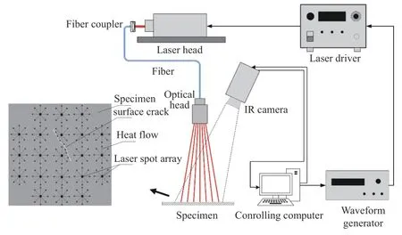
Fig. 8. Schematic diagram of the fiber-guided LAST system and the basic principle for crack inspection.
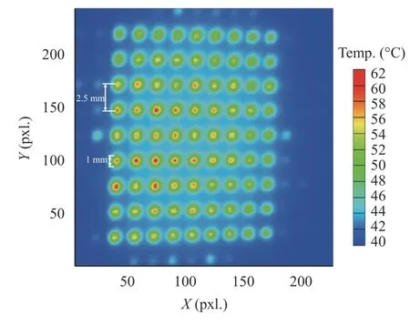
Fig. 9. Measured thermal image with 9 × 9 laser array spots (1 pixel sees 0.1 mm).
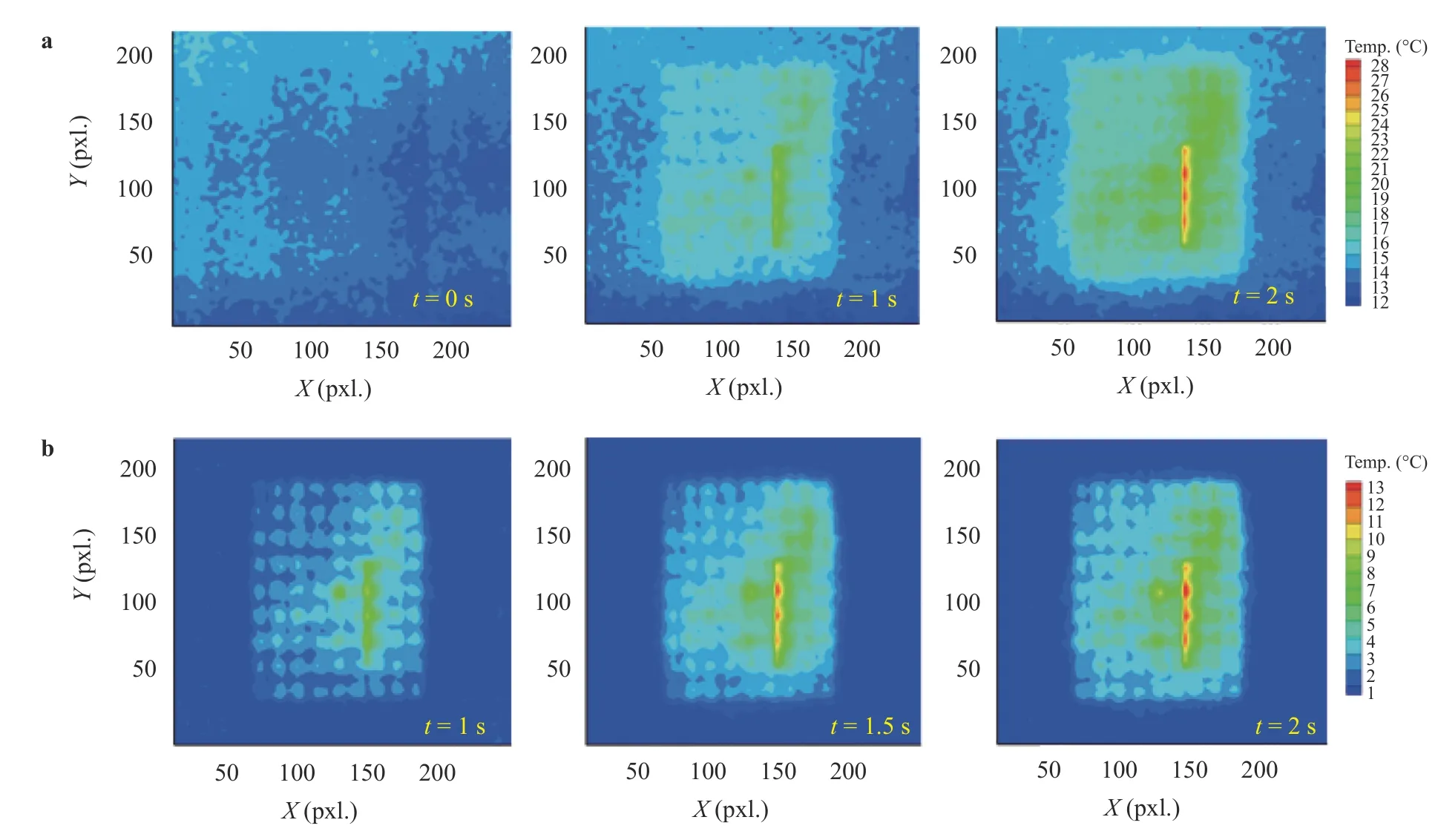
Fig. 10. Thermal images at different record time measured on the stainless steel plate with a crack. a Raw thermal images, b computed background free images
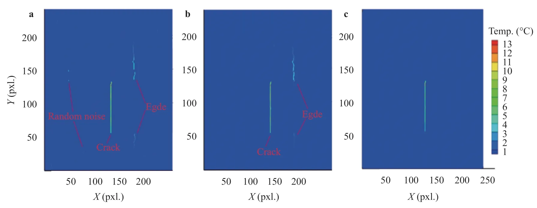
Fig. 11. Noise elimination procedure for extreme value image. a Crack extraction with a single background free image, b crack extraction with multiple background free images, c final image without edges
To verify the performance of the developed LAST system, a measurement on a steel specimen without crack was firstly carried out. The specimen is coated with black lacquer at first to increase the absorption rate and surface emissivity. Figure 9 shows the experimental results. From measured thermal image, the 9 ×9 laser array spots can be clearly observed and the laser size and spacing meet well with the inspection requirement.
The inspection experiment is also conducted on an uncoated stainless steel specimen with an electric discharge machining (EDM) crack. In experiment, a 9 × 9 la ser spot array with the duration of 2 s was generated as heating source. The 2 s heating period and 8 s cooling period were recorded by the IR camera. Figure 10(a) shows the raw thermal images at different recording times. Although the crack heat pattern can be recognized in the raw thermal images, the laser spots is not so clear as that shown in Fig. 9. This is because the emissivity of the uncoated specimen is low and the surface is uneven. In order to reduce the background noise, the cold image subtraction was applied and the obtained background free images are shown in Fig. 10(b). It can be seen that the background noise is mainly removed, and both the laser array spots pattern and crack heat pattern become clearer. However there is still some noise in these images but the noise is randomly distributed while the crack heat pattern in each thermal image is almost the same.
After calculating the background free image sequence, the surface pattern can be greatly eliminated. Then the holder exponent analysis method is adopted to isolate the crack from heat source pattern in the background free sequence. However, in this method the crack is extracted from a single image at a certain frame but not from the whole image sequence, which may cause the loss of information and increment of noise level. To solve this problem, an improved crack extraction method is proposed. Instead of applying the holder exponent analysis to a single background free image for crack imaging in the previous method, the superposition of several images are applied to further reduce the random noise that may cause false indication of cracks. The details of the improved crack extraction method are given in Ref. [20]. Figure 11(a) shows the extracted crack image with a single backgroud free image. The crack can be clearly recognized thouth there is still some random noise. Figure 11(b)shows the crack extraction results by using the improved method. A significant reduction of noise can be witnessed by superimposing multiple crack isolated images from t = 1 s to t = 2.5 s (a total of 13 frames from frame 9 to 21). At last, the edges are removed by comparing with the heating area in original thermal image, as shown in Fig. 11(c).
Online inspection of surface cracks at elevated temperature is more challenging for the health monitoring of the Tokamak structures. An experimental investigation has been also conducted to investigate the feasibility of LAST method for surface crack inspection at elevated temperature. In the experiment, a steel plate with a fatigue crack was heated to different temperature.When the temperature of the specimen reached to 373 K, 473 K,and 573 K, corresponding LAST measurements were conducted respectively. Figure 12(a) shows the raw thermal images measured on the specimen at different initial temperatures with a 2 s laser heating pulse. At room temperature, the laser spot array can be clearly observed and the crack can be identified without particular image processing. However, with the rising of initial temperature, the thermal contrast of thermal images becomes much lower and the crack indication is also masked by the background noises. Figure 12(b) shows the corresponding background free images for the raw thermal images. After the image processing, as the background noise is stationary, only the laser induced temperature variation is retained. Figure 13 shows the final crack extraction results for the thermal images of different initial temperatures. The results reveal that the good detection capabilities of LAST can be maintained for surface cracks even at elevated temperature.
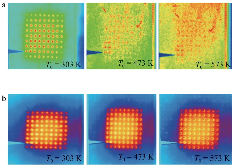
Fig. 12. Thermal images measured on a specimen with different initial temperatures. a Raw thermal images, b computed background free images

Fig. 13. Final crack extraction results for thermal images of different initial temperatures.
A review of the recent progress on the UT and IRT methods for Tokamak PFCs inspection by authors is given in this paper. In order to evaluate the quality of the PFCs during manufacturing and in service, various new NDT methods for different inspection objects and application environment are introduced and evaluated.
Firstly, an UT system using a focused probe to inspect the bonding quality of the W/Cu W/Cu monoblocks is introduced.The HHF testing demonstrated the feasibility of the rotating UT system and inspection procedure. Second, a non-contact, coupling-free and flexible EMAT scanning testing system with a robotic inspection manipulator is described for the in-vessel inspection of delamination defect in FW. The delamination defects with different size in a simulated FW specimen can be properly detected by using the C-scan EMAT. Third, researches on the feasibility of the laser thermography technique for remote and online detection of delamination and surface crack in FW were introduced. The detectability of the LIRT method can reach to a depth-to-width ratio as small as 1.0. In addition, a flexible fiber-guided LAST testing method can be used to measure the surface cracks in FW. Finally, it was proved that cracks can still be visualized with the aid of some image processing even at an elevated temperature.
Acknowledgments
The authors would like to thank the National Magnetic Confinement Fusion Program of China (Grant 2013GB113005) and the National Natural Science Foundation of China (Grants 51577139 and 11502192) for funding.
杂志排行
Theoretical & Applied Mechanics Letters的其它文章
- Mechanics of Tokamak fusion components
- Delamination strength of HTS tape under transverse tensile stress and its enhancement by using different Ag layer depositing temperatures
- Numerical study of MHD mixed convection under volumetric heat source in vertical square duct with wall effects
- Progress on design and related R&D activities for the water-cooled breeder blanket for CFETR
- Numerical methods for the magneto-mechanical coupling analysis of invessel components in Tokamak devices
- Considering for the blanket structure scheme of HCCB DEMO
