Delamination strength of HTS tape under transverse tensile stress and its enhancement by using different Ag layer depositing temperatures
2019-07-08JunWangCeSunLiuCongXingyiZhangYouheZhou
Jun Wang, Ce Sun, Liu Cong, Xingyi Zhang*, Youhe Zhou
Key Laboratory of Mechanics on Disaster and Environment in Western China attached to the Ministry of Education of China, Lanzhou University, Lanzhou 730000, China
Department of Mechanics and Engineering Sciences, College of Civil Engineering and Mechanics, Lanzhou University, Lanzhou 730000,China
Keywords:YBCO coated conductor Transverse tensile stress Delamination strength Depositing temperature Energy disperse spectroscopy
A B S T R A C TFor the application of second generation high temperature superconducting coated conductors(CCs) with layered structures, thermal mismatch between different components and electromagnetic force exerted in superconducting layer in a working magnet can cause transverse tensile stress, which would result in delamination behavior. Therefore many research groups have designed experiments to measure the delamination strength and dedicate to improving that.However, the reason of the discrete distribution of measured data has still not get quantitatively studied, besides, there are lack of investigations on the method of changing depositing conditions to improve the delamination strength except by adding an additional metal layer. In this work, we adopt an anvil test device and obtain delamination strengths as 29.6 MPa of YBa2Cu3O7-x(YBCO)/buffer and 114.6 MPa of buffer/substrate by combing energy disperse spectroscopy (EDS)detection. The reason of discretized measurement data on the delamination strength is explained.Moreover, we find that different temperatures during Ag deposition determine the bonding force of Ag and YBCO layer. The Delamination strength between Ag and YBCO layer increases from 4.4 MPa to larger than 114.6 MPa with temperature elevated from 30 °C to 100 °C. Hence we present a novel method for improving the delamination strength of YBCO CCs by setting an optimal temperature of Ag deposition.
Comparing with low temperature superconducting (LTS)wires and the first generation of high temperature superconducting (HTS), like Bi-based superconducting tapes, second generation (2G) HTS, represented by YBa2Cu3O7-x(YBCO)coated conductors (CCs), have distinct superiority in the many aspects, such as strong mechanical properties, high current density, high critical temperature, high irreversible magnetic field, and especially low cost [1, 2]. Those merits make the 2G HTS as a new star that has been scaled up for diverse applications in the power industry. Hence numerous emerging electric devices, including strong magnet, cables, energy storages etc.are designed and fabricated based on 2G HTS CCs [3-5]. Since the practical applications of these HTS CCs require the abilitiesof deformation while carrying high current densities, these CCs are achieved by depositing ceramic superconducting layer onto a metallic substrate with various methods, such as RABiTS MOD[6] and IBAD MOCVD [7] techniques. Despite different adopted fabrication techniques, these CCs have layered structures so that they can be winded into magnet coils or cables. In the winding process, superconducting layer is subjected tensile strain in the longitudinal direction, besides, in an epoxy impregnated pancake coil, cumulative radial stress develops during cooling down process; When the magnet is energized, huge Lorenz force initiates because of the interaction between the magnetic field and high currents, this would result in the hoop and tensile radial stresses [8], of which the former is along the tape length and later in transverse direction. Though research results have proved that tensile stresses in both directions have effects on degrading critical current, transverse tensile stresses that cause severe degradation are in the magnitude of dozens MPa [9-14], contrastively, that along tape length are usually in the magnitude of hundreds of MPa [15, 16]. Correspondingly, the developing technology has dramatically improved tape mechanic properties that the limit of stretching stresses has been increased to 600-700 MPa [17, 18], which is enough for hoop stress in strong field magnet application. Nevertheless, there still exists no well-established technology for elevating the limit of delamination stress to a level of engineering security. This indicates the study of delamination behavior is more significant. In the experiment of measuring the delamination strength, anvil method is often used[9, 11, 12]. Slitting as a usual fabrication process, reducing delamination strength was reported because of localized damage to the microstructure at slitting edge [9]; stress induced by thermo mismatch between CCs and epoxy caused delaminating in pancake coil was investigated [10]. This delamination behavior was firstly reported caused by electro-magnetic force [19, 20].There were some works to improve the delamination strength by adding an additional layer of copper or stainless steel [11]. But special techniques in the depositing process to improve delamination strength are rarely reported. In this work, different depositing conditions of Ag layer on delamination strength are investigated. Delamination strengths among different layer interfaces are firstly obtained, at last, the reason of discretized measurement data of delamination strength is explained.
Commercially available Hastelloy C276 substrates with buffer layers (12 mm width) are purchased from Shanghai Creative Superconductor Technologies Co., Ltd. The selected target is YBCO ceramic, purchased from Adelwitz Technologiezentrum GmbH. The YBCO layers are then deposited by in situ deposition via inverted cylindrical direct current (DC) sputtering and have a thickness of 0.1 μm. In the deposition procedure, the growth temperature is set as 720 °C and with the equal ratio of argon and oxygen. After sputtering, the tapes are annealed at 450 °C for 45 min under an oxygen atmosphere of 1 atm. Next,the Ag layers are deposited by DC magnetron sputtering while the tape temperatures are set as 30 °C, 65 °C, 100 °C, 150 °C, and 200 °C. Then we cut the 12 mm width tape into 6 mm width and the tapes are electroplated with copper of 20 μm thick. The critical current of the final CCs is 1.2 MA/cm2.
To avoid the localized damage to the microstructure of conductor by cutting process [9], we select the 4 mm width anvil.Figure 1 shows the delamination assembly. The CCs are soldered between the anvils with 97 In-3Ag solder and pulled anvil through a universal testing machine. The details of the procedure can be found in our previous work [13, 14].
After delamination test, we analyze the components of the delamination surfaces by energy disperse spectroscopy (EDS) to determine which layer of the conductors is destroyed. Besides,through the digital image processing of the photos of delamination surfaces, the destroyed areas of each layer are acquired. The delamination strengths of different temperatures for the Ag layer fabricating are shown as in Fig. 2. Results manifest when the temperature increases from 30 °C to 200 °C, the mean delamination tensile strength increases first from 21.6 MPa to 48.8 MPa and then remains nearly constant.
In Fig. 3, from the photographs and EDS spectra of delaminated conductors, we know which layer of the conductor is destroyed. From EDS spectra of Fig. 3a, there have Y, Ba, and Cu elements, we know the purple material is YBCO layer and other elements belong to the buffer and substrate layer below the YBCO layer. Because the detection depth of EDS can reach several micrometers and the thickness is 0.1 mm of YBCO layer and 0.2 mm of buffer layer. There contain the elements of layers below YBCO layer. The La, Mn, and Mg elements of Fig. 3b show the yellow material is LaMnO3and MgO buffer layer. The Ni, Cr, and Mo elements of Fig. 3c mean the blue material is Hastelloy substrate.
The detailed delamination surfaces of different temperatures are listed in Table 1. At 30 °C, the delamination surface is mainly YBCO layer, it means that the delamination mainly occur between YBCO (purple) and Ag layer. The delamination strength is just 4.4 MPa. The delamination strength can increase to 48 MPa when the delamination occur between buffer (yellow)and substrate layer (blue) at 100 °C.
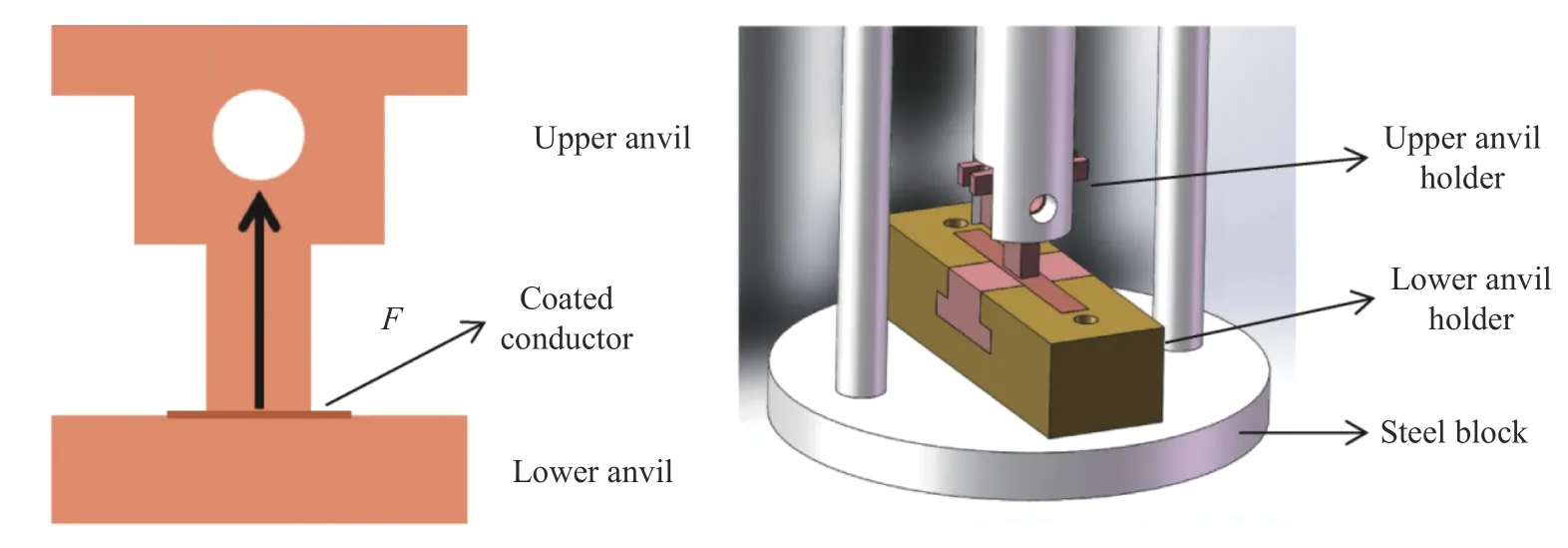
Fig. 1. Schematic of transverse tension test
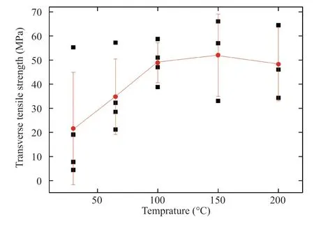
Fig. 2. Delamination strength versus different temperatures of Ag depositing.
When the temperature increases, the delamination distribute among YBCO, buffer layer and substrate. The colors of the photographs in Table 1 are obtained by Matlab program, then the destroyed areas of each layer are acquired. Using the correlation with the destroyed areas of each layer and the whole delamination strength, we get the delamination strength of each layers as

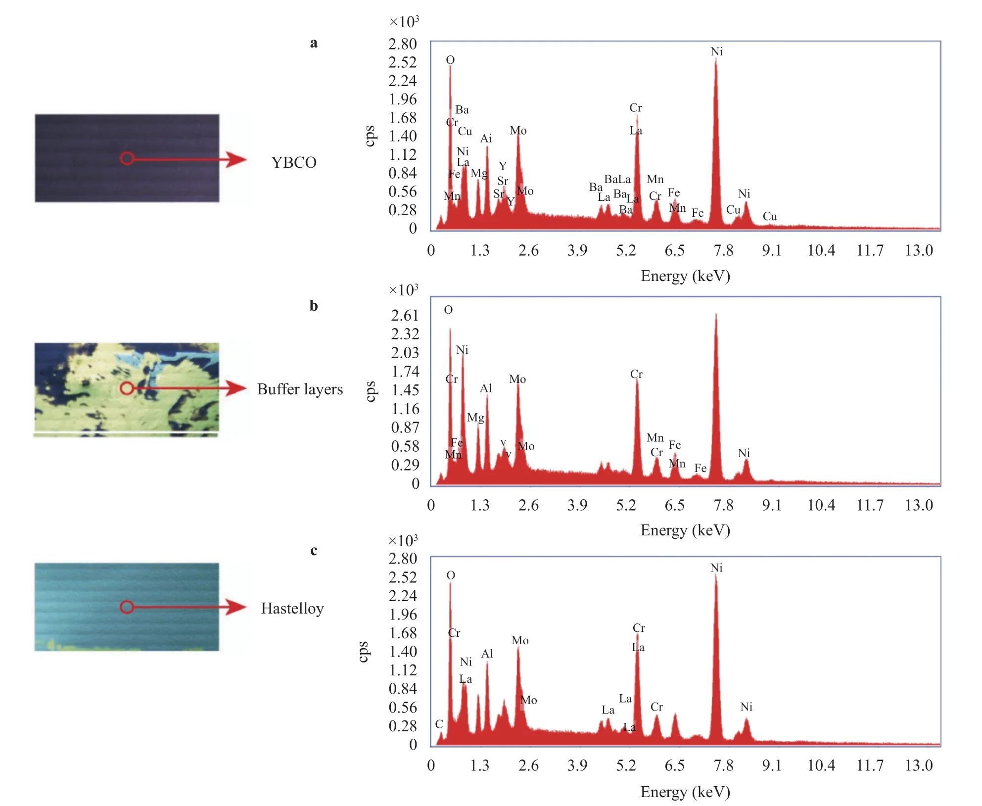
Fig. 3. Photograph and EDS spectra of delaminated conductor. a Delamination between Ag and YBCO layer at 30 °C. b Major delamination between YBCO and buffer layer. c Major delamination between buffer and Hastelloy substrate.
The delamination strength between Ag and YBCO layer is 4.4 MPa when Ag is fabricated at 30 °C. The strength is 29.6 MPa between YBCO and buffer layer and 114.6 MPa between buffer layer and substrate. It is well close to the experimental data 117 MPa [12]. The adhesion of Ag and YBCO layer increases when the temperature of Ag fabricated increases. At 30 °C, the delamination strength is just 4.4 MPa. It is larger than 114.6 MPa when the temperature is higher than 100 °C, because the delamination does not occur between Ag and YBCO layer. Then we explain the reason of discretized data of delamination strength. The micro cracks tend to appear in the weakest layer during the transverse tension, then micro cracks extend until the CC is destroyed. Since the thickness is 0.1 μm of YBCO layer and 0.2 μm of buffer layer, the micro cracks can easily penetrate YBCO or buffer layer and destroy the YBCO or buffer layer.Delamination area of different layers varies and the measured delamination strength fluctuates.
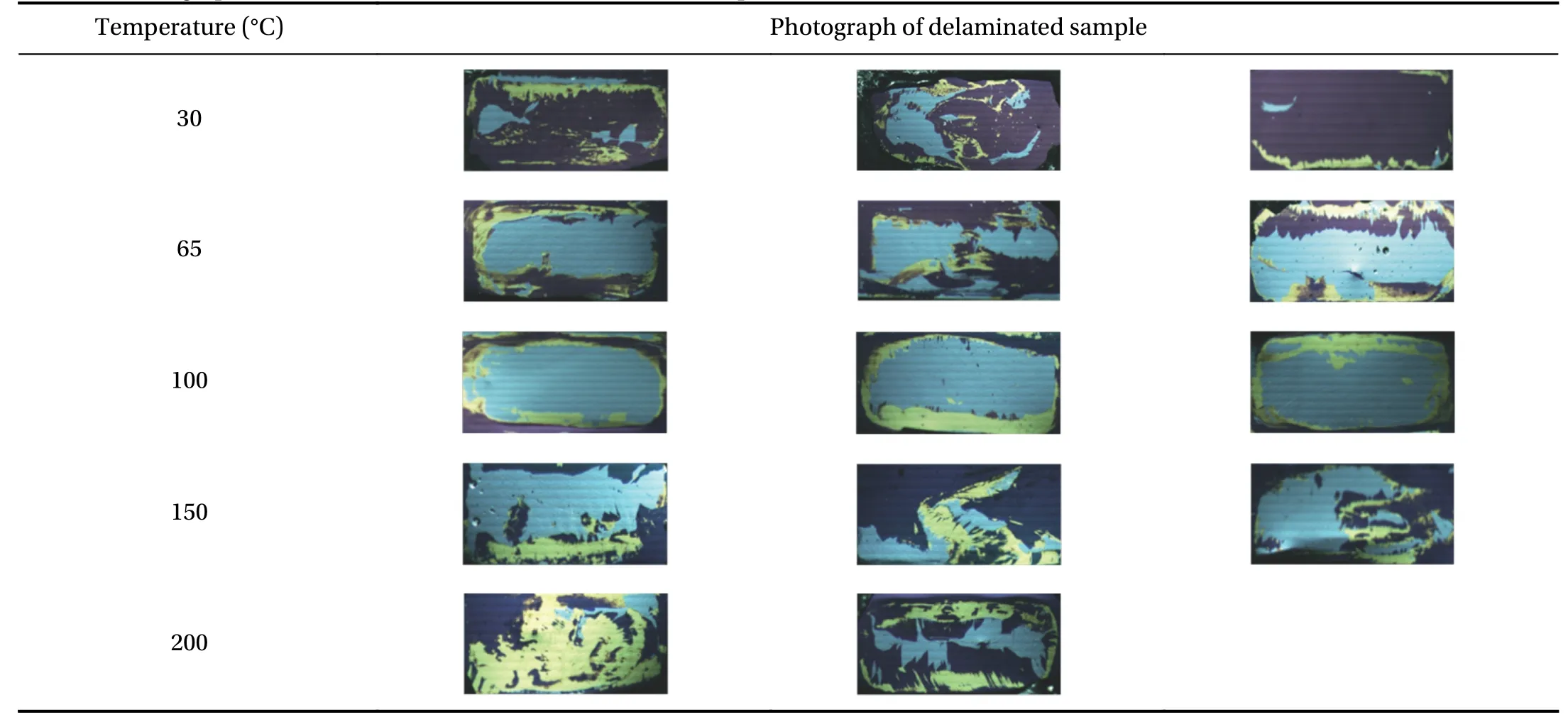
Table 1 Photograph of the delaminated conductor of different temperature
The transverse tensile stresses of YBCO CCs are investigated by using the anvil test. Based on EDS and digital image processing, the delamination strength of each layer is obtained.Since the CCs have layered structures, the delamination strength of the CCs depends on the weakest layer. We present a method to improve the delamination strength of CCs by elevating the strength between Ag and YBCO layer. The mean delamination tensile strength increases from 21.6 MPa to 48.8 MPa when the growth temperature of the Ag layer rises from 30 °C to 100 °C.
Acknowledgements
This work was supported by the National Natural Science Foundation of China (Grants 11622217 and 11872196), the National Program for Special Support of Top-Notch Young Professionals. This work was also supported by the Fundamental Research Funds for the Central Universities (Grants lzujbky-2017-ot18, lzujbky-2017-k18, and lzujbky-2018-9).
杂志排行
Theoretical & Applied Mechanics Letters的其它文章
- Mechanics of Tokamak fusion components
- Numerical study of MHD mixed convection under volumetric heat source in vertical square duct with wall effects
- Progress on design and related R&D activities for the water-cooled breeder blanket for CFETR
- Numerical methods for the magneto-mechanical coupling analysis of invessel components in Tokamak devices
- Progress on the ultrasonic testing and laser thermography techniques for NDT of tokamak plasma-facing components
- Considering for the blanket structure scheme of HCCB DEMO
