Progress on design and related R&D activities for the water-cooled breeder blanket for CFETR
2019-07-08SonglinLiuXiomnChengXueinLeiChenKehengJingXiLiHuiBoJihoWngWnjingWngChnghongPengPengLuMinLiKiHung
Songlin Liu*, Xiomn Cheng Xuein M, Lei Chen Keheng Jing, Xi Li, Hui Bo,Jiho Wng, Wnjing Wng Chnghong Peng, Peng Lu, Min Li Ki Hung
a Institute of Plasma Physics, Chinese Academy of Sciences, Hefei 230031, China
b Advanced Energy Research Center, Shenzhen University, Shenzhen 518060, China
c University of Science and Technology of China, Hefei 230026, China
Keywords:Chinese fusion engineering testing reactor WCCB blanket Research and development
A B S T R A C TThe water-cooled ceramic breeder (WCCB) blanket is one of the blanket candidates for Chinese fusion engineering testing reactor (CFETR) and is being developed at the Institute of Plasma Physics, Chinese Academy of Sciences (ASIPP). This paper reviews design and evolution of the WCCB blanket for CFETR, and presents a new WCCB blanket design according to the latest CFETR core parameters (major and minor radii are R = 7.2 m and a = 2.2 m, respectively) and missions.This new design is expected to satisfy multiple CFETR operation modes of 0.2, 0.5, 1.0, and 1.5 GW fusion power and achieve tritium self-sufficiency. The feasibility of the updated blanket design is evaluated from the aspects of neutronics and thermo-hydraulics. Furthermore, the research and development (R&D) activities supporting to the WCCB blanket for CFETR are reported, including the design code, the water loop experiments, the pebble bed modeling and experiments, and the components fabrication technology.
Fusion energy is sustainable and environmentally friendly,which is a promising option to satisfy the increasing demands for energy under the suppression of global warming. Chinese fusion engineering test reactor (CFETR) is the next device on the roadmap for realization of fusion energy in China, which aims to bridge the gap between international thermonuclear experimental reactor (ITER) and demonstration reactor (DEMO). During the past several years, significant progresses have been made in both physics and engineering design for CFETR. The core parameters of CFETR have been updated from R = 5.7 m, a = 1.6 m to R = 7.2 m, a = 2.2 m. More specific and challenging requirements are accordingly proposed to the reactor design [1].
The blanket plays a pivotal role in CFETR, which is responsible for tritium breeding to produce fuel, energy converting to generate electricity, and shielding neutron to protect superconductor magnet. Specifically, the water cooled ceramic breeder(WCCB) blanket is one of the blanket candidates for CFETR,which has been developing for over five years at the Institute of Plasma Physics, Chinese Academy of Sciences (ASIPP) [2, 3].Pressurized water at 15.5 MPa is chosen as coolant with 285 °C inlet/325 °C outlet temperature, since this kind of water coolant has been widely and maturely applied in commercial fission reactors. A mixed pebble bed of Li2TiO3and Be12Ti is employed as tritium breeder and neutron multiplier, a reduced activation ferritic/martensitic steel acts as structural material, and tungsten is used as armor material for the first wall (FW).The original design of the WCCB blanket was based on R = 5.7 m, a = 1.6 m core parameters. A new blanket design was proposed in 2018 with the latest core parameters (major radius R = 7.2 m, minor radius a =2.2 m). Its objectives are expected to cover the CFETR operation modes of 0.2, 0.5, 1, and 1.5 GW fusion power and achieve tritium self-sufficiency (tritium breeding ratio (TBR) ≥ 1.1).
This paper reviews the progress of design and research and development (R&D) activities related to the WCCB blanket for CFETR. The second section describes the WCCB blanket design evolution and features. The nuclear performance and thermalhydraulic performance of the new blanket are evaluated respectively. Later several key technology developments supporting the blanket design are reported, including the design code, the water loop experiments, the pebble bed modeling and experiments,and the components fabrication technology. The summary is given at last.
The original design of the WCCB blanket [3] was based on the small core paramters (R = 5.7 m, a = 1.6 m) under the fusion power of 0.2 GW. On the toroidal cross section of one typical blanket sector (22.5°), blankets numbered 1#-10# have different shapes and structures but similar design features in the radial direction as shown in Fig. 1(a). Taking 3# blanket module as an example, the poloidal height, toroidal width and radial thickness are 1200, 950, and 800 mm respectively, seen in Fig. 1(b).The reduced activation ferritic/martensitic (RAFM, e.g. CLF-1 or CLAM) steel is selected as structural material. So the blanket module is basically a steel box enclosed by the back plate (BP),side walls (SWs), and a U-shaped FW coated with 2 mm of tungsten on the plasma facing side. Three stiffening plates SPs divide the blanket module into 4 sub-modules. Each sub-module contains a winding cooling plate (CP) for the sake of uniform flow distribution in the cooling channels. The breeding zones (BZs)are multi-layered shown in Fig. 1(c), inside which mixed pebble beds of Be12Ti and Li2TiO3are used as breeding materials. To improve the TBR, two layers of beryllium pebble beds are employed as separate neutron multipliers. The pressurized water enters the blanket through the BP and then flows upwards along the poloidal direction in the FW. After collecting in the manifold,the coolant flows through the CPs in series. The stiffening plates(SPs) are cooled at last before the coolant getting out.
To extract the tritium produced in the BZs, low pressure purge gas flows toroidally in the pebble beds. The purge gas channels are integrated in SPs and SWs. This scheme is in favor of reducing the purge gas pressure drop by decreasing the flow distance.
In this original design, less CPs are designed in the WCCB blanket modules under 0.2 GW fusion power so that higher TBR of 1.21 is achieved. Nevertheless, the blanket should be redesigned under 1.5 GW fusion power with more CPs to ensure adequate cooling, yet the TBR decreases to 1.12 [3]. However, if CFETR convert the fusion power among different levels, one set of blankets should be replaced by another set, and this will cause huge engineering cost. In addition, there are still some issues to be addressed. One issue is the difficulty of fabrication of the winding CP. Another is the large total pressure drop of the water coolant under 1.5 GW fusion power due to the employment of once-through hydraulics design.
The updated design of WCCB was proposed corresponding to the latest core parameters (R = 7.2 m, a = 2.2 m) defined in 2018. The blanket design aims at covering the CFETR multiple fusion power (0.2, 0.5, 1.0, and 1.5 GW) while satisfying the tritium self-sufficiency. The WCCB blanket module poloidal segment definition is shown in Fig. 2(a), each segment has 6 inboard modules and 6 outboard modules. The 12 blanket modules along the poloidal direction have different shapes but similar design features. 3# blanket is taken as an example to describe the detailed structure and common features of the updated blanket module (shown in Fig. 2(b)). The module features a steel box enclosed by the FW, upper and lower cover plates, and BPs.The FW is a U-shaped plate and covered with tungsten castellated tiles on the plasma facing side. The SPs are incorporated to enhance the steel box and divide the blanket module into 4 submodules. The purge gas channels are integrated in the upper cover plate and lower cover plate to achieve the poloidal flow of purge gas. The blanket box is filled with mixed breeder of Li2TiO3and Be12Ti. In the updated blanket design, the cooling plates in the previous design are replaced by cooling tube assemblies(CTA) for higher TBR, better manufacturing feasibility and easier pebble beds filling. An array of 23 CTA is embedded in the mixed breeder pebble bed zone of each sub-module to remove the nuclear heating power and ensure adequate cooling. Each CTA consists of three multi-bended cooling tubes and some ribs.Referred to the Europe-water cooled litium lead blanket (EUWCLL) cooling tube parameters [4], the cooling tube utilizes DWT and has an external diameter of 13.5 mm and internal diameter of 8 mm. Each cooling tube is bended several times in the toroidal and radial directions. The distance between toroidal tubes of each cooling tube is increasing in the radial direction based on nuclear heating distribution. Based the new blanket design requirements, three independent cooling systems (CSs)are adopted to control the temperature of blanket under different fusion power. CS 1 is mainly used to cool the structural components (FW, SPs, and cover plates). CS 2 and CS 3 are used to cool the breeder zones. In each CTA, one cooling tube of CTA is connected to CS 2 and the other two tubes are connected to CS 3. When CFETR operates at a higher fusion power (≥0.5 GW), all of the three cooling systems are put into use. When CFETR operates at the fusion power of 0.2 GW, only CS 1 and CS 2 are put into use to raise the temperature of breeder zone for a better tritium release performance [5].

Fig. 1. Original design of the WCCB blanket. a Blanket sector, b exploded view of blanket 3#, c sectional view of blanket 3# (unit: mm).
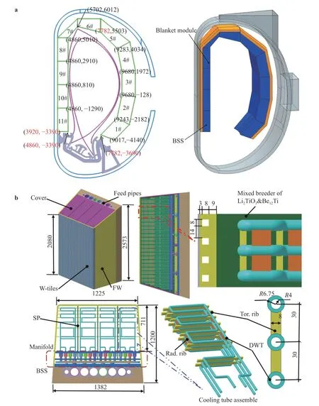
Fig. 2. Updated design of the WCCB blanket. a Blanket sector, b updated blanket structure (BSS: back supporting structure, DWT: dual-wall pressurized tubes).
A 22.5° toroidal symmetrical 3D neutronics model is developed as shown in Fig. 3. In the model, the 2 cm gaps between adjacent blanket modules are taken into account for assembly.The neutronics model of each WCCB blanket module is divided into nine main components, created as plasma-facing component (PFC), FW, BZ, cooling tube zone, the manifold, radial-poloidal stiffening plate (rpSP), SW, cover plates, and BSS. Each of these components is homogenized. The materials used in these components are listed in Table 1. The volumetric ratio of breeder Li2TiO3to neutron multiplier Be12Ti has been optimized and the enrichment of6Li is 0.8 in the WCCB blanket. The MCNP SDEF source is defined based on the neutron emissivity matrix in CFETR plasma. The neutron emissivity matrix is obtained by equilibrium and plasma density and temperature distribution calculations, shown in Fig. 4.
The TBR analysis was performed to determine the global TBR, by MCNP5 code and IAEA fusion evaluated nuclear data library, FENDL2.1. Figure 5 shows the contribution of each blanket module to the global TBR. The result indicates that the global TBR of 1.149 for 0.5, 1.0, and 1.5 GW fusion power is slightly higher than that of 1.148 for 0.2 GW fusion power. In above neutronics analysis, it is assumed that the blanket modules are full coverage in vacuum vessel except for divertor.However, the size and number of heating port, diagnosis port,remote handling port, etc. will be different and impact on TBR under different fusion power. In follow-up work, these factors impact on TBR will be further evaluated.
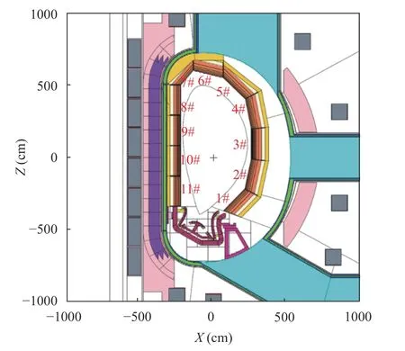
Fig. 3. Neutronics model of CFETR-WCCB.
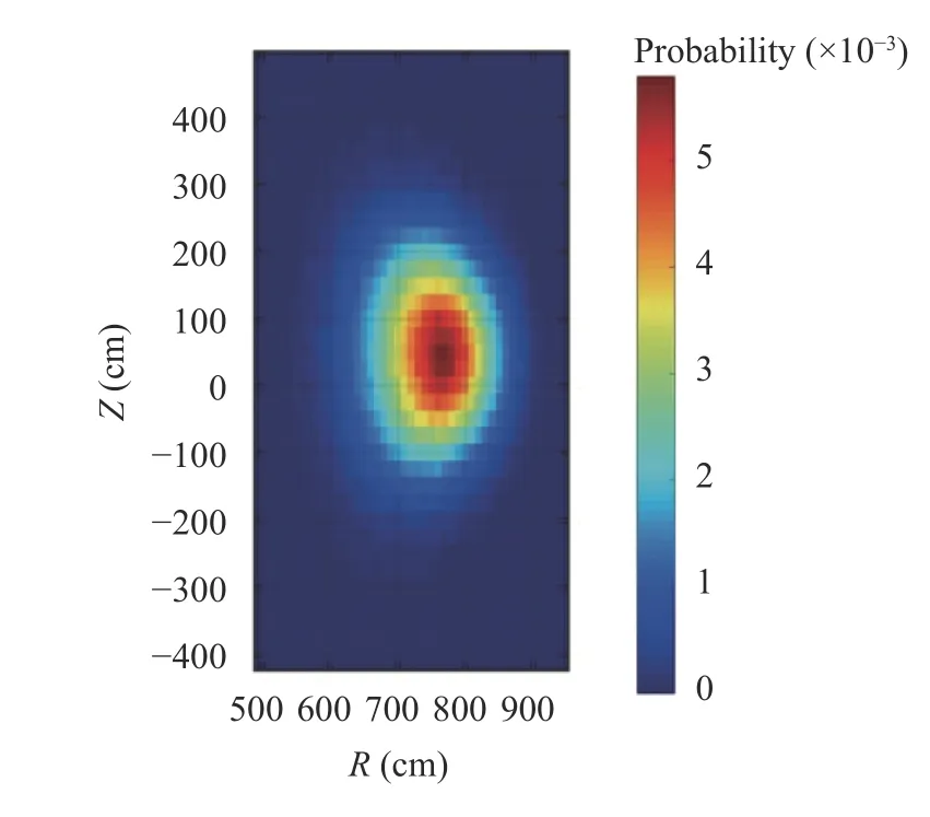
Fig. 4. Neutron source.
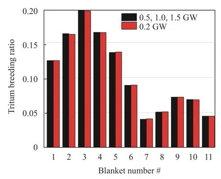
Fig. 5. Module-wide TBR distribution.
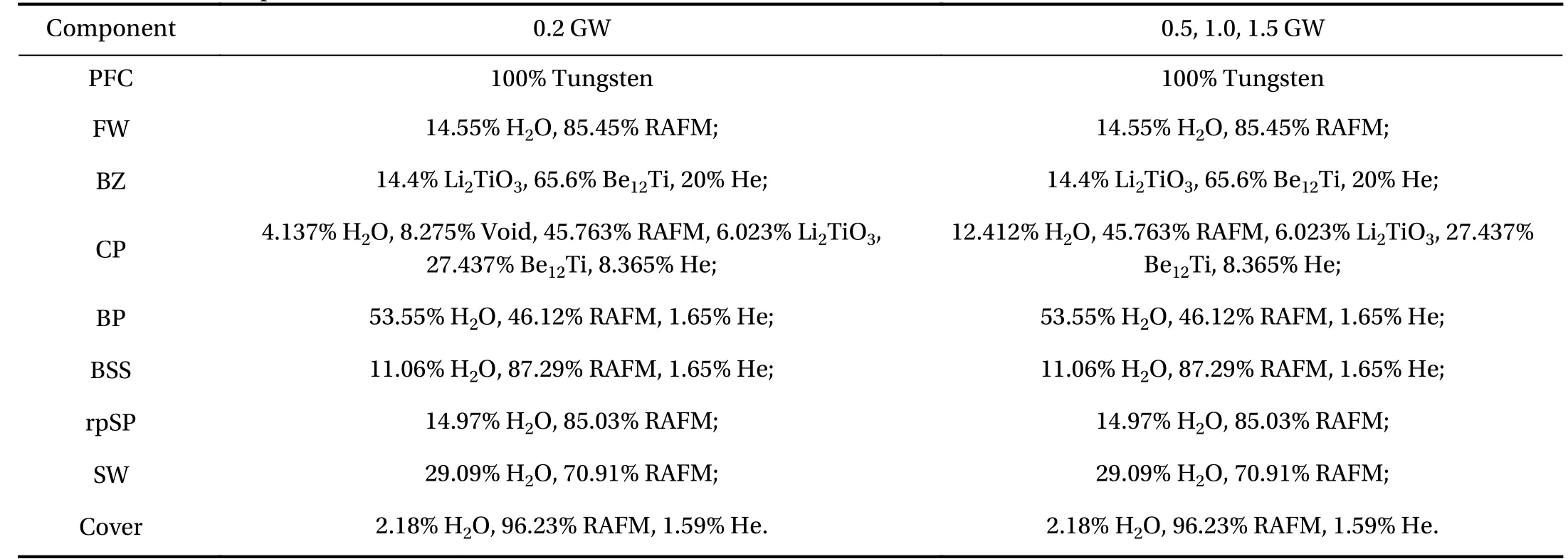
Table 1 Material composition of CFETR-WCCB
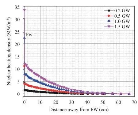
Fig. 6. Nuclear heating rate distribution at different distance away from the FW of 3# module.
The thermal-hydraulics analyses under 0.2, 0.5, 1.0, and 1.5 GW fusion power were performed using the FLUENT code. The calculation is based on a 3D slice finite element method (FEM)model including the FW, one CTA, the mixed pebble zone, SP,and BP components. Periodic boundary conditions are imposed at top and bottom surfaces of the model. The nuclear heating rate distribution of 3# module under different fusion power along the radial direction is shown in Fig. 6. The average heat flux of 0.5 MW/m2from plasma chamber is assumed. The thermal physical properties parameters are listed in Ref. [6].Table 2 illustrates the hydraulics parameters of module 3# under different fusion power.
The temperature distribution of the slice model under 0.2,0.5, 1.0, and 1.5 GW fusion power are shown in Fig. 7. It indicates that the temperature of each component can fulfill the allowable limits of materials. The temperature of breeder zones under 0.2, 0.5, 1.0, and 1.5 GW is at the range of 360 °C-515 °C,370 °C-500 °C, 452 °C-666 °C, and 515 °C-822 °C, respectively. Itcan be observed that the temperature is a little low at the rear breeder zone under 0.2 GW and 0.5 GW fusion power and this may impact tritium release process, the extent of which requires further investigation.

Table 2 Hydraulics parameters of 3# module under different fusion power
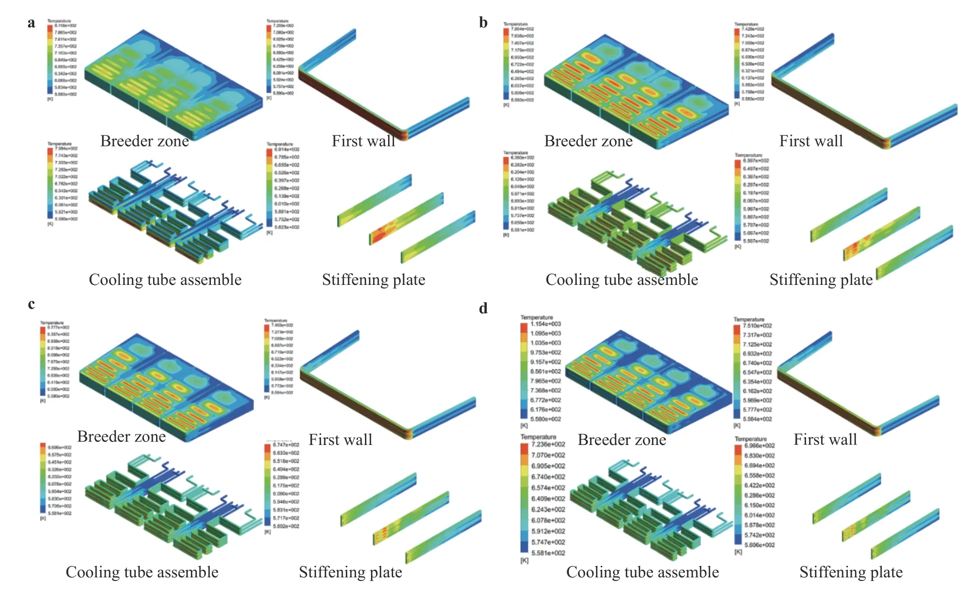
Fig. 7. Temperature field distribution of slice under a 0.2 GW, b 0.5 GW, c 1.0 GW, d 1.5 GW fusion power.
The blanket design is an iterative process for obtaining the optimal blanket structure, which involves with numerous variables and restricted conditions. Apparently, it will be a challenging work to analyze manually if there is no comprehensive tool to encapsulate the design process. The integrated platform,which couples neutronics, thermal hydraulics and mechanics calculation, and covers all the necessary variables have been developed in ASIPP and is acting as an important auxiliary tool to support the WCCB blanket design.
The evolution of this work can be seen from Ref. [7-9]. The framework mainly consists of five parts (Fig. 8): (1) The graphics user interface (GUI) layer provides convenience for humancomputer interaction, through which the geometry modeling and simulation can be achieved by only clicking the button(Fig. 9). (2) The project logical layer is used to recognize which features are ready for the following execution. (3) The methodology to obtain the optimal radial layout of blanket is included in the optimization module. (4) The simulation module activates the commercial software and delivers the calculation tasks to carry out. (5) The data layer collects the data from GUI, stores the results data and writes into the file with eligible format.There are two primary functions in this platform. Figure 10 shows the flow chart of this platform. In function 1, one specific blanket should be designed firstly, which includes the detailed radial building and 3D structure. Afterwards, the multi-physics analysis is performed continuously without iteration. In function 2, there is an optimization iteration on blanket radial building, which just requires the preliminary general radial layout in advance. Moreover, the methodology of “predict + verify” is exploited to get the optimal radial layout efficiently [8]. In the module of nuclear thermal coupled iteration, the procedures of modeling, meshing, data extracting, processing and transforming from MCNP to ANSYS are automatically executed based on the initial geometry and operating parameters. In an iterative cycle,the results of materials temperature and TBR are feedback to the regulatory system, which adjusts the arrangement of cooling channels using effective strategies until the optimal arrangement is obtained. Then, according to this 2D radial building, the integral 3D structure of one blanket unit is further built by adding the stiffening plates and arranging the channels, which is modeled in the input file using ANSYS parametric design language (APDL) that performs the thermal-mechanic analysis. Afterwards, the results are used to determine whether it is necessary to readjust the radial layout and 3D structural building for further thermal-mechanic optimization. Instead of using 3D model to do the nuclear-thermal calculation for optimization,the simplified 2D model is adopted to increase the work efficiency. Before using this tool to conduct this iterative process,the neutron wall loading (NWL) of each module is firstly calculated by 3D neutronics model, then the radial layout with homogeneous material in each layer is built in the 1D cylinder model.It can effectively calculate the power heat which is normalized to NWL in each cycle loop. Then, the heating source is transferred to the 2D model and applied in each corresponding layer for thermal hydraulic analysis [10].
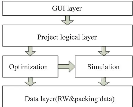
Fig. 8. Framework of this platform.
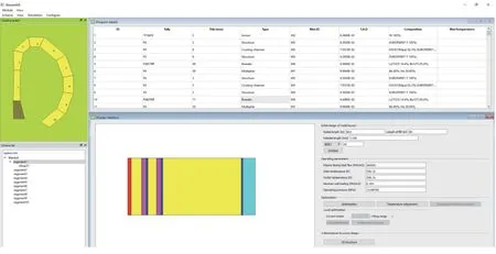
Fig. 9. GUI arrangement.
A water loop is built at ASIPP to study the thermal hydraulic characteristics of square channels in the WCCB blanket under forced circulation and natural circulation. Figure 11 shows the experiment test loop which mainly comprises of the primary loop system, primary coolant system, measurement system and other auxiliary systems. Primary loop system is mainly composed of a shield pump, a pressurizer, a pre-heater, an experimental channel, a heat exchanger, some relevant pipes and valves and other accessories. Secondary coolant system consists of an air cooling tower and a centrifugal pump. The main parameters of the loop are shown in Table 3.
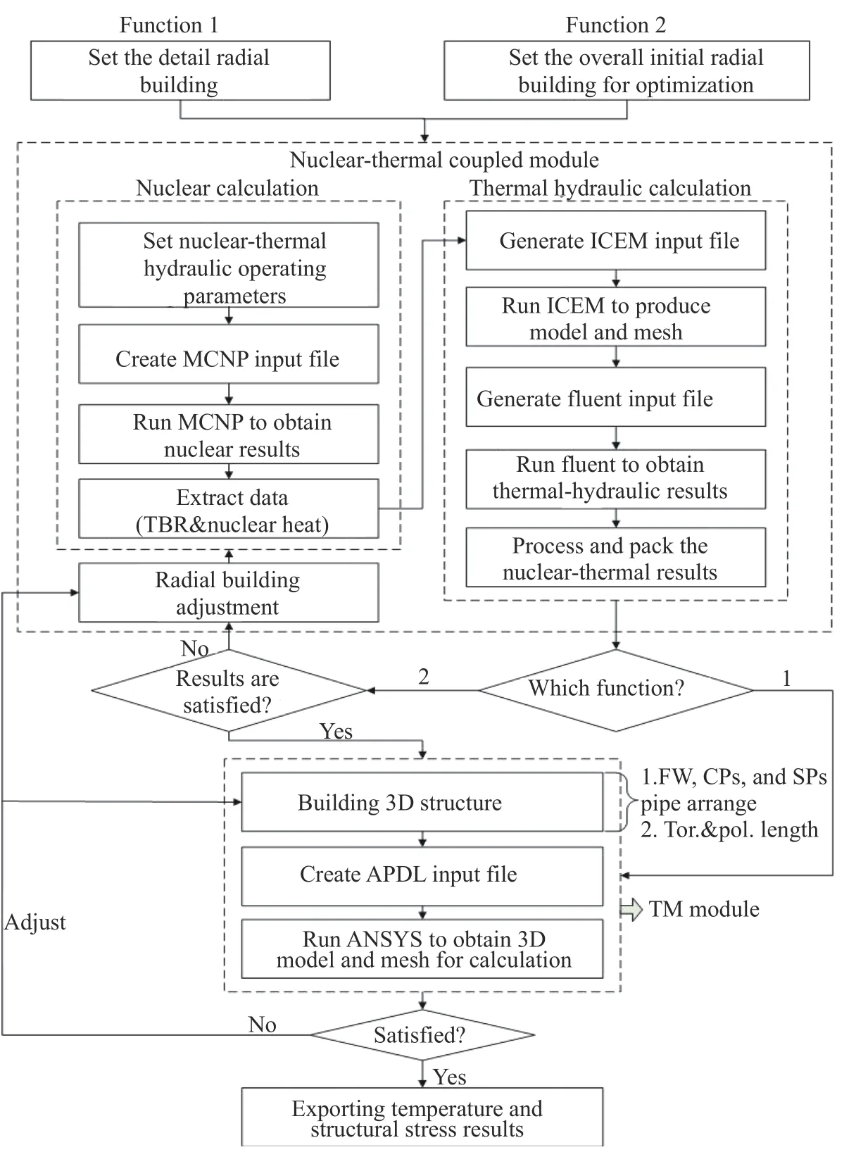
Fig. 10. Flow chart of this platform.
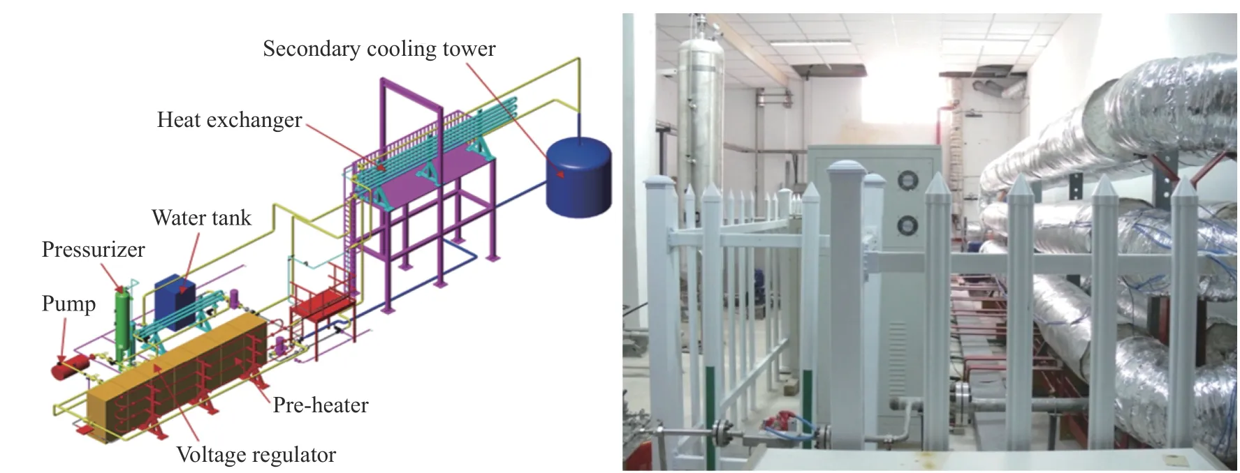
Fig. 11. Water loop facility.
Square channels with the cross section size of 8 mm×8 mm/5 mm×5 mm are used in the WCCB blanket. Thermal hydraulic design of blanket directly determines heat transfer efficiency and safe operation of fusion reactor. Therefore, thermal hydraulic characteristics of square channels should be investigated. Based on this water loop facility, following experimental studies have been completed:
(1) Under the forced circulation condition and the natural circulation condition, the single-phase water friction resistance and heat transfer experiment have been conducted. The correlations of friction coefficient and heat transfer coefficient are acquired. The experimental results show that the natural circulation heat transfer intensity is lower than that of the forced circulation in the forced circulation because of co-current mixed convective flow in the test tube [11].
(2) Experimental study has been performed to investigate natural circulation subcooled boiling characteristics in square channels of fusion blanket. Some new empirical experimental correlations are developed on the foundation of experimental data to predict heat flux, wall superheat, location of onset of nucleate boiling (ONB), and subcooled boiling heat transfer coefficient when ONB occurs in natural circulation. The experimental results show that flow instability exists in the natural circulation phenomenon. The fluctuation amplitude of flow in the natural circulation loop ascends with the increase of the heating power[12].
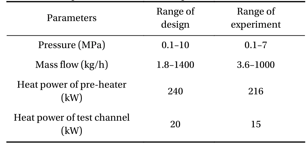
Table 3 Main parameters of the test loop
(3) For square channel in the blanket, the experimental study of dryout has been conducted. Experimental results show that the dryout heat flux increases with the increase of mass velocity and with the decrease of inlet vapor quality. Furthermore, with the increase of heat flux, the location of dryout point move to inlet of test section and the wall temperature at the dryout point increases gradually. Based on the obtained experimental data,the correlation for prediction of critical vapor quality (XDO) in the square channels is proposed [13].
Multi-sized Li2TiO3/Be12Ti mixed pebble beds were configured as the tritium breeder zones in the current WCCB design due to their higher tritium production and effective thermal conductivity (ETC) comparing to the typical Li4SiO4or Li2TiO3pebble beds. Besides, beryllium pebble beds were also assembled in the front zones of WCCB to multiply the neutron and thus enhance the TBR. In order to support the design and analysis of WCCB, the thermo-hydraulic features and the thermomechanical characteristics of the related pebble beds were investigated by the experimental and numerical methods.
Experimental measurements including purge gas pressure drop and ETC of pebble beds have been carried out by using the pebble bed test platform at ASIPP [14, 15] (see Fig. 12). The helium loop can provide a helium flow at 0.1-2 MPa, 20 °C-500 °C with a maximum flow rate of 80 Nm3/h. It can be connected with different experimental sections for the measurement of purge gas pressure drop and the effective thermal conductivity.Figure 13(a) shows some experimental results of pressure drop for the unitary pebble beds and mixed pebble beds. In these experiments, glass pebbles were used to replace ceramic pebbles because the pebble physical properties almost has no effects on the pressure drop. From these experimental data it can be concluded that the pressure drop of mixed pebble beds is within the range of pressure drop of unitary pebble beds only consisting of the corresponding larger and smaller particles. Figure 12(b)shows the pebble bed experimental section for ETC by using hot wire method. The influence of temperature on the ETC of ceramic pebble beds has been investigated as shown in Fig. 13(c,d). The ETC of Li2TiO3pebble bed increases from 0.90 to 1.04 W/(m·K) with a temperature rising from 30 °C to 390 °C, while ETC of Li4SiO4pebble bed increases from 0.55 to 0.64 W/(m·K)with a temperature from 50 °C to 390 °C. ETC of the Li2TiO3/Be12Ti mixed pebble beds will be measured in the future work.
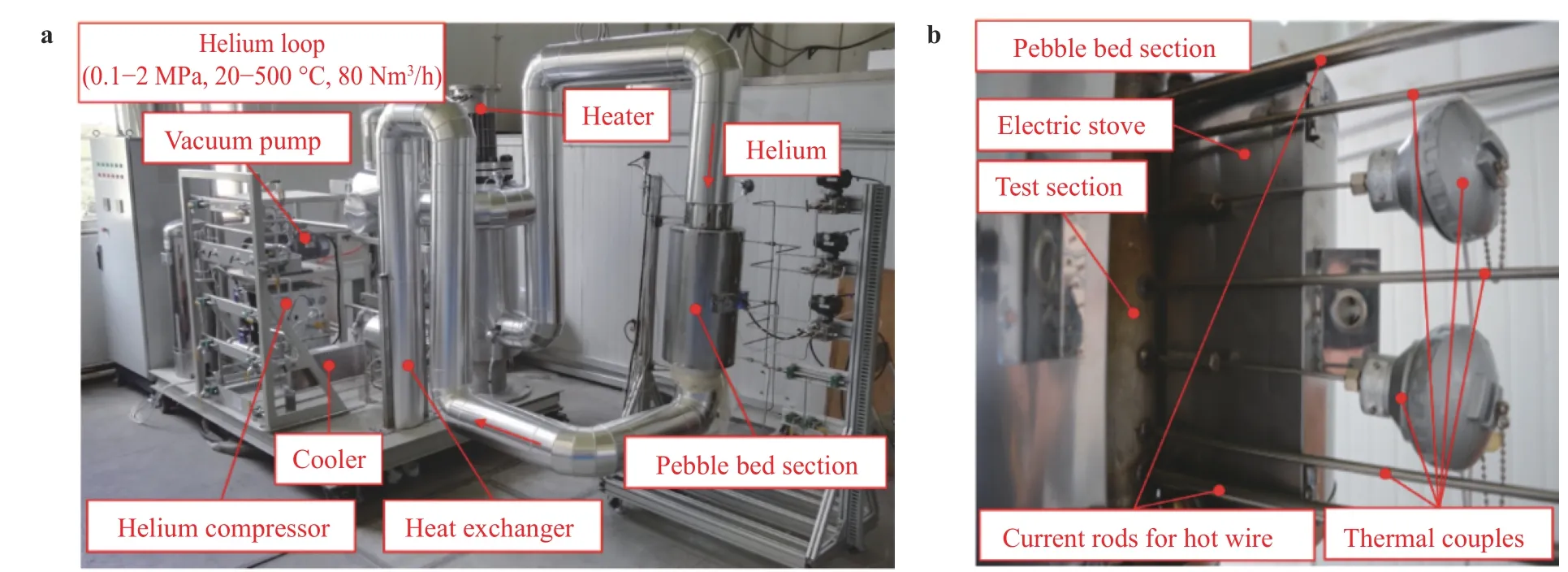
Fig. 12. Pebble bed test platform. a Helium loop to measure the pressure drop of purge gas, b test section to measure the effective thermal conductivity of pebble beds.
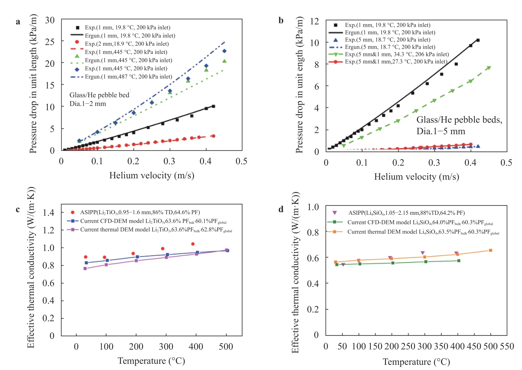
Fig. 13. Purge gas pressure drop and effective thermal conductivity in pebble beds. a Influence of diameter, helium temperature and pressure on the purge gas pressure drop. b Purge gas pressure drop in mixed pebble beds. c Effective thermal conductivity of Li2TiO3 pebble bed. d Effective thermal conductivity of Li4SiO4 pebble bed.
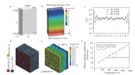
Fig. 14. DEM-CFD modeling of pebble beds. a, b, and c The geometry, pressure contour, and velocity distribution of a beryllium pebble bed(pebble diameter 2.0 mm). d, e, and f The geometry, temperature contour, and effective thermal conductivity of the Li2TiO3/Be12Ti mixed pebble bed. Large Be12Ti pebble, 2.0 mm; tiny Be12Ti and Li2TiO3 pebble, 0.4 mm.

Fig. 15. Thermal DEM model for the thermo-mechanical simulation (beryllium pebble beds). a Pebble bed and its Voronoi tessellation. b Heat flow distribution under the mechanical load. c Thermo-mechanical simulation and validation.
Concerning the pebble bed simulation work, the packing structure for mixed pebble beds were optimized by the discrete element method (DEM). A possible mixed pebble bed which meets the requirements of neutronics can be found when the large-to-tiny particle diameter ratio is not less than 5 and the large-to-total particle volume ratio is around 0.6-0.7 [16]. Besides, the purge gas pressure drop and ETC of both unitary and mixed pebble beds were estimated by the DEM-CFD method[17, 18], as shown in Figs. 13 and 14. ETC of the Li2TiO3/Be12Ti mixed pebble bed were found roughly between 2.0 W/(m·K) and 4.0 W/(m·K) when the temperature varies from 100 °C to 900 °C.More recently, a thermal DEM model based on the Voronoi tessellation was developed and validated to evaluate the thermomechanical characteristics for the pebble beds used in fusion blankets [19]. As an example, the Voronoi tessellation for a beryllium pebble bed was shown in Fig. 15a, and its heat flow distribution as well as effective thermal conductivity under the mechanical load are shown in Fig. 15b, c. ETC of the beryllium pebble bed increases about 3 times with the uniaxial stress loading up to 6 MPa.
The WCCB blanket of CFETR is designed with complex structure to achieve the multifunction mission. The manufacture of the blanket component is a rather difficult work, including the material selection, subcomponents fabrication and integration assembly. In the development of manufacture technology for the CFETR WCCB blanket component, Tungsten (W) and RAFM steel were chosen as the preferred plasma facing materials(PFM) and structure materials. To get a better heat transfer capability, these two materials must be joined by metallurgical bonding method. But it is difficult to join W to steel directly for their different thermo physical properties such as melting points, coefficients of thermal expansion (CTE), which will lead to large residual stress when cooling to room temperature. In addition, the U-shape FW of the blanket, with a series of long square tube, also needs the welding technology to achieve the bonding of steel/steel in its fabrication.
At ASIPP, the hot isostatic pressing (HIP) bonding technology for W/steel and steel/steel has been developed. In the W/steel bonding, selection of interlayer materials is the key to achieve the well bonding. Here Ni, Cu, and Ti have been tried as the interlayer materials considered of the weldability and irradiation activation, respectively. Firstly, the low activation element of titanium (Ti) [20-22] has been chosen as the interlayer considered to the irradiation environment of blanket system. To study the effect of Ti interlayer on the bonding quality of W and steel joints, W/Ti/steel HIP experiments were conducted under 930 °C, 100 MPa for 2 h. The bonding quality was evaluated by microstructure analysis and mechanical tests. Intermetallics caused by atom interdiffusion would affect the bonding quality of W/Ti/steel HIP joints. Nano-indentation tests demonstrated W/Ti interfaces could be enhanced by solid solution hardening and formation of brittle phases has conducted high hardness across the Ti/steel interfaces.
Secondly, Ni and Cu have been also tried as the interlayer to modify the bonding properties of W/steel joints based on following considerations. (1) These materials own lower yield strength than Ti, indicating they will be more easily release the residual stress though the plastic strain in the HIP process. (2) These materials are more easily to diffuse into the base metal and no reaction products occurred between W/Cu/steel interfaces. Table 4 has shown the summary of the selection of interlayer materials experiment. Compared the reaction products, shear strength and failure mode, it can be concluded that the copper should be rather proper to use as the interlayer material in W/steel bonding.
In the development of technology for RAFM plates with square channels, trials were initially carried out using HIP to joint steel/steel. Two machined plates with grooves were assembled to form three channels of dimensions 8 mm×8 mm and were subjected to HIP under 1000 °C, 100 MPa for 2 h. These initial trials resulted in collapse of the channels. Subsequently,square tubes were prepared and used to fabricate the mockup with flow channels. The experimental results demonstrated that the perfect square channels have been obtained with good bonding quality, as shown in Fig. 16.
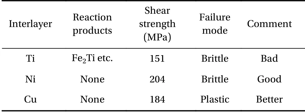
Table 4 Bonding quality of W/steel joint with different interlayer
In all, these elementary researches have provided many lessons for the further work to achieve the manufacturing of the full-size WCCB component.
As the machine size of CFETR has been increased from R =5.7 m, a = 1.6 m to R = 7.2 m, a = 2.2 m, the WCCB blanket design has been updated too. Learning lessons from the original design,the updated WCCB blanket can satisfy multiple operation modes of CFETR with the fusion power of 0.2, 0.5, 1.0, and 1.5 GW.Comparing with the original design, major changes have been made to the updated design. Firstly, the direction of the FW changes from radial-poloidal to radial-toroidal. Secondly, the array of the cooling tube assemblies replaces the cooling plates and the ribs between cooling tubes can improve heat transfer and strengthen the blanket structure. Thirdly, the purge gas sweeps the breeding zones in the poloidal direction instead of the toroidal direction. In addition, the most important change is the cooling scheme of the blanket. The FW and BZ are cooled separately by using three sets of independent cooling systems to adapt to the fusion power ranging from 0.2 GW to 1.5 GW. One cooling system is used to remove the heat on the structure of the FW, the cover plates and the SPs. The other two cooling systems are employed to remove the heat deposited in breeder zones.
Based on the updated WCCB blanket, 3D neutronics investigation with heterogeneous blanket model is performed for CFETR. The TBR is 1.148 for 0.2 GW fusion power, while higher TBR of 1.149 is achieved for 0.5 GW to 1.5 GW fusion power. The thermal hydraulics performance analysis is carried out with a 3D slice model. The result indicates that the thermal conditions are compliant with the material allowable temperature limits and are beneficial to tritium release.
Key technologies are developed in support of the WCCB blanket design for CFETR. The integrated design platform which couples the neutronics, thermo-hydraulics and mechanics has been successfully developed and applied for the WCCB blanket modules design. This tool can greatly accelerate the optimization process of the blanket design. Extensive experiments are carried out on the water loop to investigate thermal hydraulic characteristics of square channel used in the WCCB blanket. The thermo-hydraulic features and the thermo-mechanical characteristics of the related pebble beds are investigated by the experimental and numerical methods, such as the ETC and purge gas pressure drop. The fabrication technologies for the WCCB blanket mockup are being developed and provide many lessons to achieve the manufacture of the full-size WCCB component in the future.
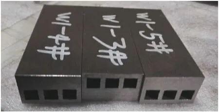
Fig. 16. Samples of HIPed steel/steel mockup with square channels.
In the next step for the updated WCCB design scheme, the integrated stresses need to be fully investigated referring to the ITER SDC-IC code. Moreover, the primary heat transfer system(PHTS) of the WCCB blanket should be designed according to the updated cooling schemes. Then safety analysis needs to be performed.
Acknowledgement
This work has been carried out within the financial support of the National Key R&D Program of China (Grants 2017YFE0300503 and 2017YFE0300604) and the National Natural Science Foundation of China (Grant 11775256).
杂志排行
Theoretical & Applied Mechanics Letters的其它文章
- Mechanics of Tokamak fusion components
- Delamination strength of HTS tape under transverse tensile stress and its enhancement by using different Ag layer depositing temperatures
- Numerical study of MHD mixed convection under volumetric heat source in vertical square duct with wall effects
- Numerical methods for the magneto-mechanical coupling analysis of invessel components in Tokamak devices
- Progress on the ultrasonic testing and laser thermography techniques for NDT of tokamak plasma-facing components
- Considering for the blanket structure scheme of HCCB DEMO
