Numerical simulation of droplet-formation in rotary atomizer
2019-07-08NaokiIgariTakuroIsoYuNishioSeiichiroIzawaYuFukunishi
Naoki Igari, Takuro Iso, Yu Nishio, Seiichiro Izawa*, Yu Fukunishi
Tohoku University, Aramaki-aoba 6-6-01, Aoba-ku, Sendai, Japan
Keywords:Smoothed particle hydrodynamics (SPH)Rotary atomizer Grooves Droplet
A B S T R A C TNumerical simulations of the liquid flow scattering from rotary atomizers are performed using an incompressible smoothed particle hydrodynamics (SPH) method. The influence of grooves at the edges of the atomizers on the formation of ligaments and droplets is investigated changing the numbers and shapes of the grooves. As a result, it is found that small droplets are likely to be generated when the number of grooves is large and the depth of grooves is deep. It is also found that the grooves work more effectively in bell-cup atomizers than in disk type atomizers.
Rotary atomizers have been widely used in the coating process of industrial products such as automobiles. The liquid paint scattering from the atomizers is atomized and transported with the help of a shaping air flow. Since the size of produced droplets strongly depends on the shape of atomizers and their operating conditions, better understanding of the breakup process of scattering liquid film is absolutely necessary to improve the coating efficiency while keeping the coating quality.
A number of studies have been conducted to reveal the liquid atomization process in rotary atomizers. For example, Corbeels et al. [1] investigated the influences of, the rotational speed of the atomizer, the flow rate, the liquid viscosity and the surface tension on the Sauter mean diameter (SMD) of the generated droplets. They revealed that the SMD was strongly influenced by the operating conditions of the atomizer and the physical properties of the liquid when the speed of rotation was 20000 rpm or less, while their influences could be negligible when the rotational speed was larger than 20000 rpm. Ménard et al. [2] numerically captured the surface deformation during the atomization process of a high-speed spray shed into an ambient gas using a combined method of the level set method and volume of fluid(VOF) method. However, the whole phenomenon is still not revealed yet, since the breakup and the atomization processes of thin liquid film take place in an extremely short time and in a small scale [3, 4] .
In this study, numerical simulations are performed for the rotary disk atomizers and the bell-cup atomizers using an incompressible smoothed particle hydrodynamics (SPH) method.Especially, the effect of the grooves at the edge on the atomization process is investigated. The computational domain is limited within a narrow fan-shape area at the atomizer edge to save the computational cost while maintaining the resolution.
SPH method have been originally developed for compressible flows. We have made it applicable to incompressible flows using a density homogenization algorithm based on the predictormodifier method [1] . In this method, the particle velocities are iteratively corrected every time step to suppress the local density deviations instead of solving the pressure Poisson equation.First, the particle velocity v(t) of the previous time step tis chosen as the initial value of the velocity predictor at time step t. Then, particles move tentatively with

Since the velocity predictor of Eq. (1) is chosen irrespective of the motion of other particles, the density distribution becomes uneven after all particles move. Thus, a velocity corrector is computed aimed at smoothing the density gradient as,

Here, C is the constant that determines the amount of correction,is the reference density of the fluid, andis the density at the tentative particle location. W is a cubic spline kernel. After adding the modifiersto the predictors, all particles are moved again using the new predictors. The new predictor is expressed as,By repeating this process,gradually approaches. However,it is known that this correction process brings in additional numerical viscosity. So, in the computations, the number of iterations N is fixed at N = 5. The velocity of the next step is finally obtained by adding the effects of viscosity and the external forces.

Figure 1 shows the computational targets and domains of a disk type and a bell cup atomizers. Each target has the diameter of 70 mm and the thickness of 100 μm. For the bell cup case, the inner wall is inclined by 45 degrees to the plane of rotation. Each computational domain is the fan-shaped hatched region near the disk edge (-1.0 ≦ y ≦ 1.7 mm, 34.5 ≦ r ( =≦54.5 mm) and the periodic boundary condition is used in the circumferential direction. The shape of grooves is shown in Fig. 2.The green particles represent the disk surface and the red particles mark the groove positions. The grooves are placed at a regular interval in the circumferential direction. Each groove is 300 μm in radial length, d in depth and w in width.
Figure 3 shows the atomization process in the smooth disk case. The liquid film on the disk surface protrudes outside from the disk edge, as it becomes wavy in the circumferential direction. The ligaments are generated at the top locations of the wavy liquid film, and the ligaments eventually break up into small droplets.
First, the effect of groove number Ngrvis discussed by picking up a rotary disk atomizer with the grooves of w = 147 μm and 2 =50 μm. Figure 4 shows the relation between the groove numbers and the averaged ligament numbers. The error bar in the figure denotes the standard deviation in each condition, and the black dashed line indicates a straight line of Nlig= Ngrv. When Ngrv=180, more ligaments are formed than the grooves. On the contrary, for the Ngrv= 420 and 600 cases, the ligament numbers are smaller than the groove numbers. The former case is because there are ligaments made in between the grooves, while the latter case is due to the phenomena where two flows passing through two neighboring grooves join together at the lateral side of the disk. The latter case phenomena are indicated by red circles in Fig. 5.
The distributions of droplet diameters when Ngrv= 180 and 600 are shown in Fig. 6. The result of a smooth disk is also shown for comparison. When the groove number is 180, the peak at 150 μm which existed in the smooth disk case vanishes, and droplets of various sizes are formed. When the groove number is increased to 600, the deviation of droplet diameters becomes small and a sharp peak is found around 150 μm. These results indicate that the deviation of droplet diameters can be reduced by choosing an appropriate groove number. In the following discussion,the groove number Ngrvis fixed to 600.
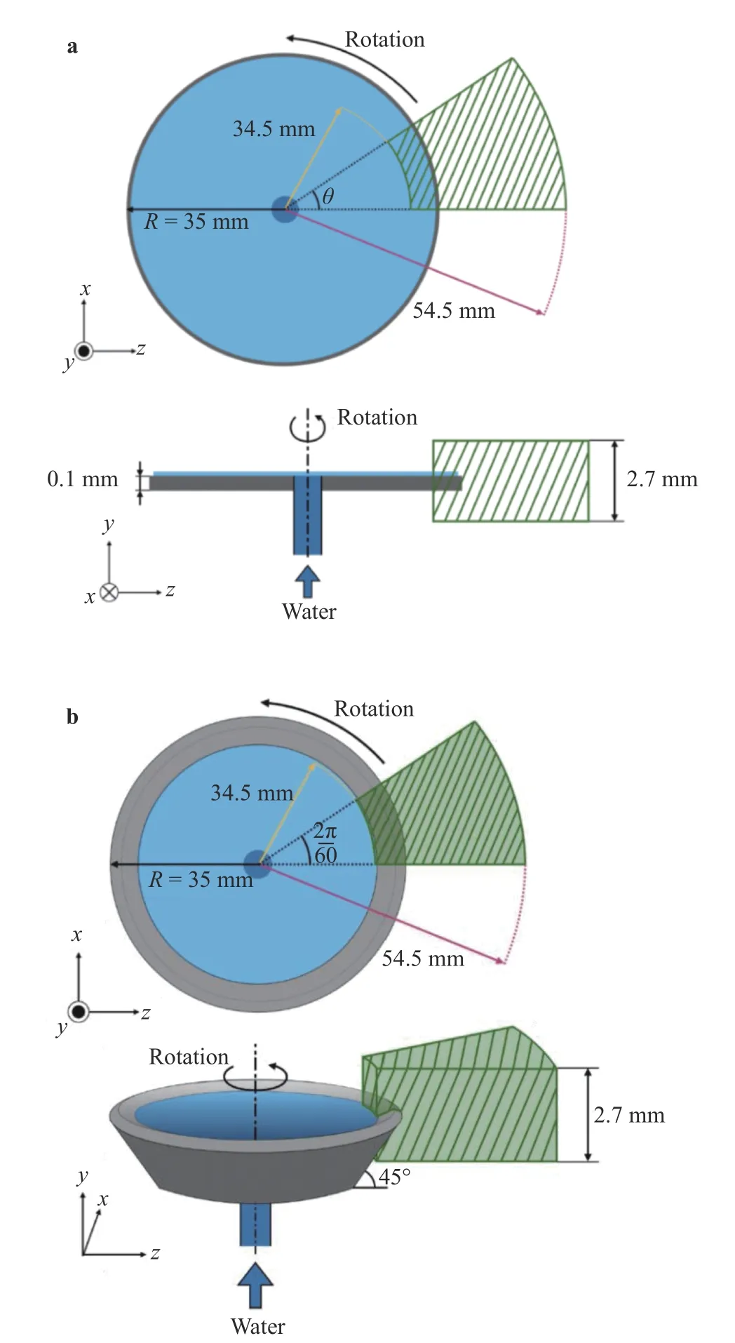
Fig. 1. Schematic view of target and domain of computation. a Disk atomizer, b bell-cup atomizer.
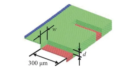
Fig. 2. Geometry of grooves
Tables 1 and 2 summarize the variations of mean droplet diameters for the disk and the bell-cup atomizers. Three groove width w cases of 110 μm, 147 μm and 220 μm, and three groove depth d cases of 25 μm, 50 μm and 75 μm are presented. The effect of change in the groove width is relatively small compared with change in the groove depth. The mean diameter of the produced droplets tends to decrease in inverse proportion to the groove depth, especially for the bell-cup atomizer. Generally, the size of droplets is determined by the thickness of each ligament,i.e., the volume per ligament. The ligament number of the bellcup atomizer is the same as the groove number 600 for all cases except for the shallow groove of d = 25 mm. This is probably because the centrifugal force works more effectively and steer the liquid into the grooves in the bell-cup atomizer, so the ligaments are more likely to be fixed at the groove locations.
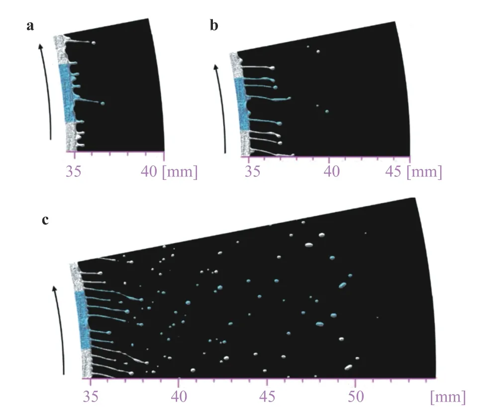
Fig. 3. Snapshots of flow fields of smooth disk (Ngrv = 0) at different time. a t = 1.05 ms, b t = 1.5 ms, c t = 2.7 ms.
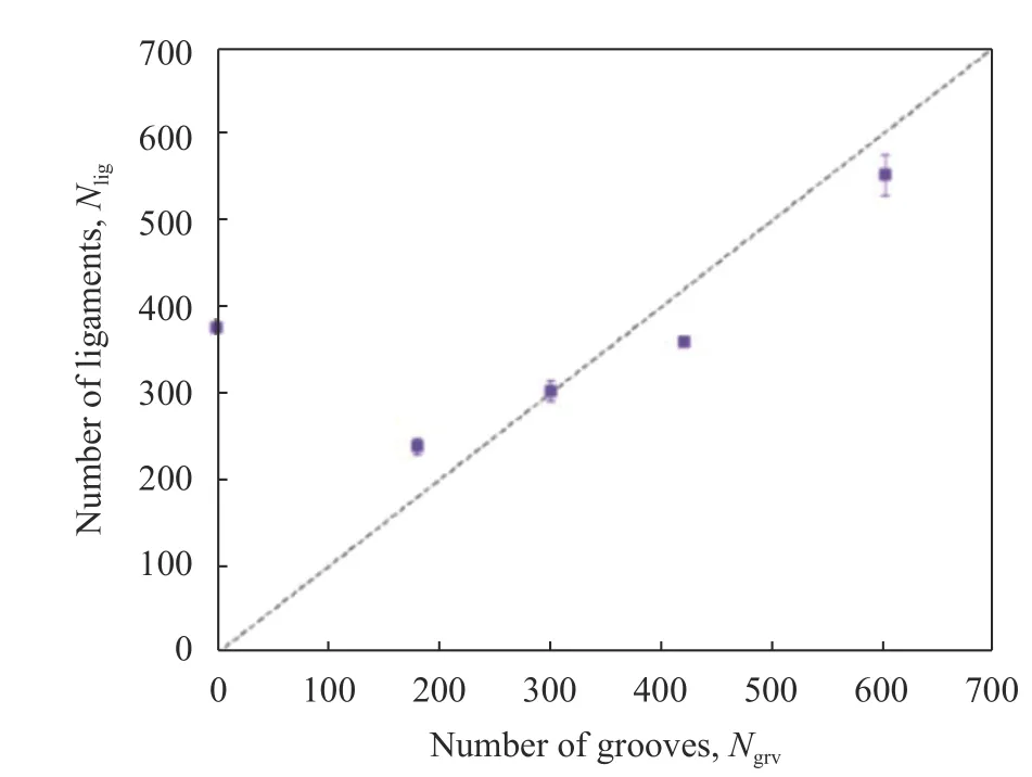
Fig. 4. Time-averaged ligament number Nlig versus groove number Ngrv. Black dashed line denotes the line Nlig = Ngrv.

Fig. 4. Time-averaged ligament number Nlig versus groove number Ngrv. Black dashed line denotes the line Nlig = Ngrv.
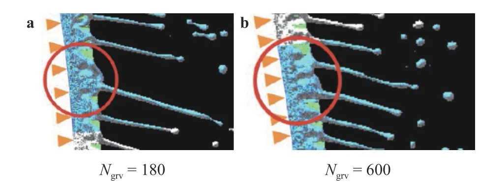
Fig. 5. Enlarged view near the edge. Groove locations are marked by orange arrows.
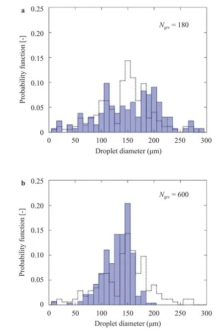
Fig. 6. Comparison of probability functions of droplet diameters when a Ngrv = 180 and b Ngrv = 600. Dotted line is the result of smooth disk.

Table 1 Comparison of mean droplet diameter for different width w when Ngrv = 600 and d = 50 μm.

Table 2 Comparison of mean droplet diameter for different depth d when Ngrv = 600 and w = 147 μm.
Numerical simulations were performed using an incompressible SPH method to investigate the droplet formation process for the disk and the bell-cup rotary atomizers equipped with grooves at their edges. As a result, it was found that the bell-cup atomizer had an advantage in terms of generating the droplets of uniform diameters, because the centrifugal force worked to direct more liquid into the grooves.
杂志排行
Theoretical & Applied Mechanics Letters的其它文章
- Mechanics of Tokamak fusion components
- Delamination strength of HTS tape under transverse tensile stress and its enhancement by using different Ag layer depositing temperatures
- Numerical study of MHD mixed convection under volumetric heat source in vertical square duct with wall effects
- Progress on design and related R&D activities for the water-cooled breeder blanket for CFETR
- Numerical methods for the magneto-mechanical coupling analysis of invessel components in Tokamak devices
- Progress on the ultrasonic testing and laser thermography techniques for NDT of tokamak plasma-facing components
