Heat transfer performance for DCLL blanket with no-wetting insulator walls
2019-07-08HulinHuangShimouYinGuipingZhu
Hulin Huang*, Shimou Yin, Guiping Zhu
College of Astronautics, Nanjing University of Aeronautics and Astronautics, Nanjing 210016, China
Keywords:Convection heat transfer Nano coating wall Computational fluid dynamics Magnetohydrodynamic effect Criterion equation
A B S T R A C TMagnetohydrodynamic (MHD) effect and heat transfer are two key issues for design of dual coolant lead lithium (DCLL) blanket. Flow channel insert (FCI) has been applied to decouple the liquid metal from the walls to efficiently decline MHD pressure drops and reduce heat losses from the liquid metal for increasing bulk exit temperatures of the blanket. However, there are still big pressure drops and a higher velocity jet located at the gap flow. Moreover, the FCI made from silicon carbide (SiC) constitutes a complex blanket structures which potentially causes special flow phenomena. In the present work, the characteristics of fluid flow and heat transfer in the DCLL blanket channel are investigated for the first wall (FW) sprayed a layer of no-wetting nano coating(NWNC) on its inner surface. The results show that the pressure drop with NWNC wall is oneorder magnitude lower than that with FCI in the general DCLL blanket. The Nusselt number on the NWNC wall is about half of that on the general wall. On this basis, a heat transfer criterion equation of DCLL channel is achieved for the NWNC wall without FCI. The results are compared with that criterion equation of general wall conditions, which indicates the criterion equation can well predict the convection heat transfer of DCLL channel.
The liquid metal blanket (such as liquid lithium lead (PbLi))is a main candidate for fusion reactor first wall because of its high tritium production and easy heat extraction characteristic[1-3]. There is, however, a great magnetohydrodynamic (MHD)pressure drop in liquid metal blanket. It is still a key problem to be solved although it has been investigated by many researchers for the last decades. At the same time, the reaction between neutrons and lithium forms inhomogeneous large internal heat sources which produces great temperature rise for liquid metal fluid. The high export temperature of liquid metal is desired for improving the energy conversion efficiency, but the maximum value is limited because of the material constraint. In order to solve these problems, the feasibility flow channel insert (FCI) inserted in blanket between wall and liquid metal has been investigated in recent years. Wei [4] carried out the theoretical analysis and numerical simulation on the China fusion engineering test reactor (CFETR) liquid metal flow of blanket with FCI by the FLUENT software. The results showed that MHD pressure drop decreased greatly when FCI was applied in the dual coolant lead lithium (DCLL) blanket, but the liquid metal would appear reversed flow when the pressure equalization slot (PES) was located at the side-layer of gap flow. Parametric investigation has also been performed to address the impact of FCI electrical conductivity and duct length on MHD flow by Sutevski et al. [5]. The results showed that FCI appeared to provide more effective pressure equalization way compared with the no FCI condition. Xu et al. [6] conducted a three-dimensional (3D) MHD flow simulation based on an electrical potential formula by using a consistent and conservative scheme. The characteristics of pressure drop and velocity distribution of liquid metal in a poloidal duct with FCI showed a pressure fluctuation which might introduce MHD flows instability while PES and pressure equalization holes(PEHs) located at Hartmann wall or side wall. MHD pressure drop and thermal deformation of 16 kinds of FCI geometric characteristic ducts were investigated by Chen et al. [7] under an external strong magnetic field. The results showed that the width of gap and thickness of FCI played important roles for MHD pressure drop and structural safe. The increasing of FCI thickness or gap width could increase the MHD pressure drops in the bulk flow, and wider gap might lead to larger stress on FCI (maximum principal strain could reach 0.00129) which could be harmful to structural safety [8]. Smolentsev et al. [9] and Vetcha et al. [10] performed numerical simulation on instability and transition in MHD flows for a special context of liquid-metal blanket applications. The results showed that instabilities were related to either boundary layers or bulk Hunt layers, typically associated with high-velocity jets. For the liquid-metal flows with volumetrically heating, two types of turbulence were observed in the blanket.
The application of FCI can lead to complex channel structures and strong flow instability and some other special flow phenomena [11]. The different wall thickness may lead to unsymmetrical velocity distributions for the jets near the two side walls and a “wavy” behavior velocity profiles in the side and Hartmann boundary layers because of the MHD effect, which was beneficial to convection heat transfer [12]. However, heat transfer required to keep the temperature of the first wall within tolerable limits, so heat transfer without and with additional turbulence promotion (TP's) by means of mechanical and electromagnetic turbulence promoters were measured experimentally for both electrically insulated ducts and thin walled, electrically conducting ducts of rectangular shape by Barleon et al. [13]. Results showed mechanical TP's used in the test section with insulated walls improved the heat transfer up to 7 times compared to that of slug flow, but the corresponding pressure drop increases within the measured range of Reynolds numbers (Res) by up to 300%. For reducing MHD pressure drop and decreasing heat transfer to FW, a lot of coating effect has been studied on the blanket channel. For example, the Al2O3coating prepared by Glasbrenner et al. [14] with hot dip aluminum method, has a good surface quality, a tight bonding with the matrix and a good gradient distribution of elements such as aluminum and iron.The outer Al2O3layer has good electrical insulation, corrosion resistance characteristic and good compatibility with liquid metal. Tanaka and Muroga [15] fabricated ceramic coating by the metal organic decomposition (MOD) method on low activation ferritic steel. Measured hydrogen permeation reduction factor was larger than 100 and concluded that MOD coating fabrication under reduced pressure would be effective and achieved superior coating performance. Jain et al. [16] used thermal analysis technique to deal with the characterization of Pb83Li17alloy and analyzed its interaction with Al2O3coating at the reactor operating temperature. The result indicated that alumina interacted with Pb83Li17alloy at 550 °C and even higher purity argon atmosphere. Li et al. [17] made nano-crystalline Er2O3hydrogen isotopes permeation barriers (HIPB) by sol-gel method and reported its performances, including deuterium-permeation reduction factor (D-PRF), micro-structure, mechanical property and electrical property. Despite of the well performed characteristic, the electrical resistivity decreased from 9×10⁹to 9×10⁶which might be attributed to oxygen loss or deuterium invasion. Pan et al. [18] used the poly urethane insulating coating that was compatible with the metal fluid at operating temperature in the experiment and derived the MHD pressure drops of the insulation wall and conductive wall ducts. The MHD pressure drop of conducting wall duct was about two-order of magnitude higher than that of insulation wall duct, i.e.that the electrical insulation wall was an effective way to solve the problem of the high MHD pressure drop.
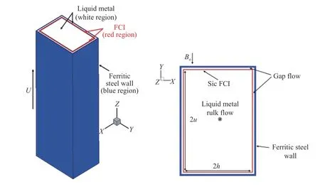
Fig. 1. Configuration of DCLL channel cross-section.
This paper aims to simplify the channel structure by replacing the FCI with the NWNC on FW inner surface. The effect on the pressure drop and heat transfer of DCLL blanket is investigated by comparing the results with or without FCI and with or without NWNC. The influence of the NWNC wall on pressure drop and heat transfer is obtained by numerical simulation, and a criterion equation is fitted according to the numerical results,which provides a theoretical basis for the optimization of DCLL structure parameters and the practical application of non-wetting nano material.
The configuration of simplified DCLL blanket channel model with an FCI is illustrated in Fig. 1, fluid flows along the Z direction with the length of the channel from z = 0 mm to z = 2000 mm, and the magnetic field is applied at the Y negative direction. The size of the X direction is 2b = 0.2 m, and the size of the Y direction is 2a = 0.3 m. The thickness of FW is 5 mm, the thickness of FCI is 2 mm, and the gap between FW and FCI is 5 mm.The physical model without FCI is same as the FCI blanket model except without flow channel insert.
The flow of viscous incompressible electrically conducting fluid under the influence of an external magnetic field can be described by the continuity Eq. (1) and Navier-Stokes Eq. (2) [6]under Boussinesq model, which express the conservation of momentum and mass

The general Ohm's law for moving conducting fluids

Maxwell equations

From Eqs. (3)-(5), the magnetic field B satisfies the following equation

Considering the flow and heat transfer characteristic of high temperature metal fluid, the fluid needs to satisfy the energy equation

In actual conditions, neutrons generated by the plasma reaction will irradiate the PbLi fluid, resulting in sustained neutron volume internal heat sources in the bulk flow. The form of neutron heat source [7] is

where x is a distance from the center of bulk flow along X coordinate, and the c is the radial width of the bulk flow. When the FCI thickness is 2 mm and the gap flow is 5 mm wide, c is 0.2 m.
The current terms and neutron heat sources can be ignored in the calculation of FCI heat transfer as the poor thermal and electrical conductivity of SiC material and the small heat generation rate under neutron irradiation. The liquid lithium lead fluid slowly passes through the rectangular cross-section blanket. The inlet velocity is 0.06 m/s, and the temperature is 460 °C at z = 0.The relative outlet pressure is 0 Pa at z = 2000 mm. On interfaces between the gap flow and outer wall of FCI, bulk flow and inner wall of FCI, the gap flow and inner wall of FW structures, solutions are coupled by ensuring the continuity of wall temperature.Simultaneously the normal component of current is zero, i.e J · n = 0, for the insulated walls. Here, n is the surface normal component of FCI and FW.
The thermal boundary of FCI and FW at z = 0 and z = 2000 mm is set to be insulated, while the third boundary conditions satisfies the all outside walls of FWs which are cooled by helium, heat transfer equation is as follows

where hfis the convective heat transfer coefficient, TSis the surface temperature of outside of FW, and TFis the surrounding coolant fluid temperature. The convective heat transfer coefficient is 4000 W/(m2·K) for outside of FW, and the helium cooling temperature is 400 °C [19].
Slip boundary conditions using linear slip length model [20]are applied at the inner surface of the FW for simulating the NWNC wall condition. The linear slip length model can be expressed as

For investigating the DCLL channel flow and heat transfer characteristics, a mesh independence has been carried out firstly with parameters of Hartmann number , Ha1712 and ,e results of the maximum velocity are shown in Table 2 within different spatial distributions,respectively, with 44 × 58 × 130, 54 × 68 × 140, 64 × 78 × 150, and 74 × 88 × 160 grids in the computational domain. It's observed that the relative error between Mesh 3 and Mesh 4 is as small as 0.027‰ from the Table 2, indicating that the numerical result is independent of the grid size. Therefore, in the premise of the computational efficiency, the spatial distribution in Mesh 3 will be adopted in the following study.
In the present numerical code, pressure-implicit with split-ting of operators (PISO) [21] algorithm is introduced to treat the pressure-velocity coupling equations including the Lorentz force term in the fluid field. The finite volume method is employed to discrete the incompressible Navier-Stokes equations and energy equation in the node-based formulation. The PISO loop consists of an implicit momentum predictor followed by a series of pressure solutions and explicit velocity corrections. During the loop,the Lorentz force term is treated explicitly as an additional force term. In order to guarantee the continuity of temperature and heat flux at the interface, boundary conditions Eq. (9) andare introduced to calculate the temperature distribution in FW-gap flow-FCI-bulk flow coupled physics field, whereanddescribe heat fluxes on solid section and fluid section of fluid-solid interface, respectively.

Table 1 Physical parameters of the fluid materials.
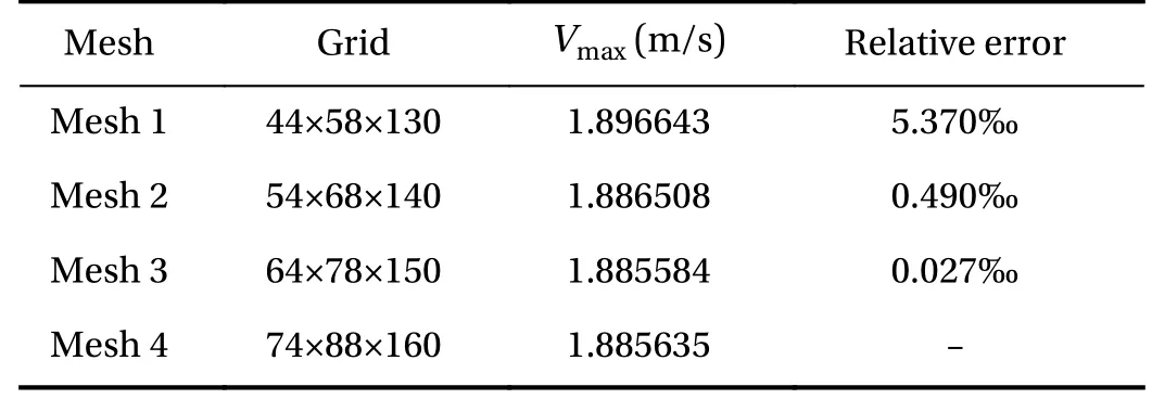
Table 2 Computational results under different spatial distributions
The typical DCLL blanket channel model with an FCI for Ha = 2552 and Re = 50106 is simulated to verify the accuracy of the MHD program. From Fig. 2 which shows the results in both our numerical model and Ref. [7], the simplified DCLL blanket channel model is proved to be capable of accurately describing the pressure drop of MHD channel.
The low electrical conductivity of the FCI, the current streamlines are blocked from bulk flow towards the gap and conductive steel wall. As a result, two symmetrical current streamlines in the gap flow along Y direction are generated by the FCI no matter FW applying the NWNC or not, which makes the bulk flow trend to Shercliff's flow [19] as shown in Fig. 3(a) and (b).The velocity is much smaller and much uniform in the bulk flow compared with that in gap flow because FW is conducting wall with electrical conductivity much higher than the FCI. The bulk flow velocity is maintained at 0.06 m/s, but the Hartmann gap flow (X plane) is almost stagnant. The Hunt gap flow (Y plane) is obviously difference. For no coating wall condition emerged a relatively large and parabolic curve jet, flow and the maximum velocity is three times of the entrance velocity (Vmax=0.197 m/s).The velocity for coating wall are uniform and two times of the entrance velocity (Vmax=0.135 m/s). The uniform velocity distribution for coating wall has little influence on the pressure drop.
The MHD pressure drop with or without NWNC varies with magnetic field are shown in Fig. 4. The MHD pressure drops increase obviously when the magnetic field is applied whether the NWNC or FCI is applied, which is disadvantageous to the fluid flow. However, the FCI can effectively reduce the pressure drop in the bulk flow. As shown in Fig. 4(a),which represents the maximum pressure difference between the entrance and exit is about 32 Pa for the 2 m channel bulk flow when the magnetic field is 1 T and velocity is 0.006 m/s, which is 0.8% of that in channel without FCI. However, the maximum pressure drops at the gap layer are still large for no coating wall condition even if the FCI is applied. The maximum gap flow pressure drop is decreased to 1/11.7, 1/30 and 1/44.1 compared with that no coating wall conditions corresponding with the magnetic field strength is 0.5 T, 1 T and 1.5 T, respectively, for an NWNC material applied on the inner surface of FW as the no-wetting wall. The pressure drop without FCI for no-coating wall condition is the largest under applied magnetic fields discussed above. However,the largest pressure drop, which is about 2.4% of that with the FCI for no-coating wall condition, appears in the case for coating wall with FCI located at gap flow.
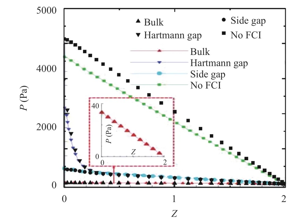
Fig. 2. Pressure drop along the flow direction. Black dots are of present simulation and color lines are of Ref. [7]
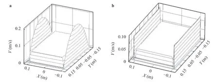
Fig. 3. Distribution of current streamlines and velocity field. a Exit velocity for no coating wall condition, b exit velocity for coating wall condition
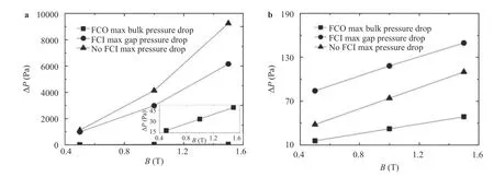
Fig. 4. Effect of the magnetic force on the MHD pressure drop. a No coating boundary, b coating boundary
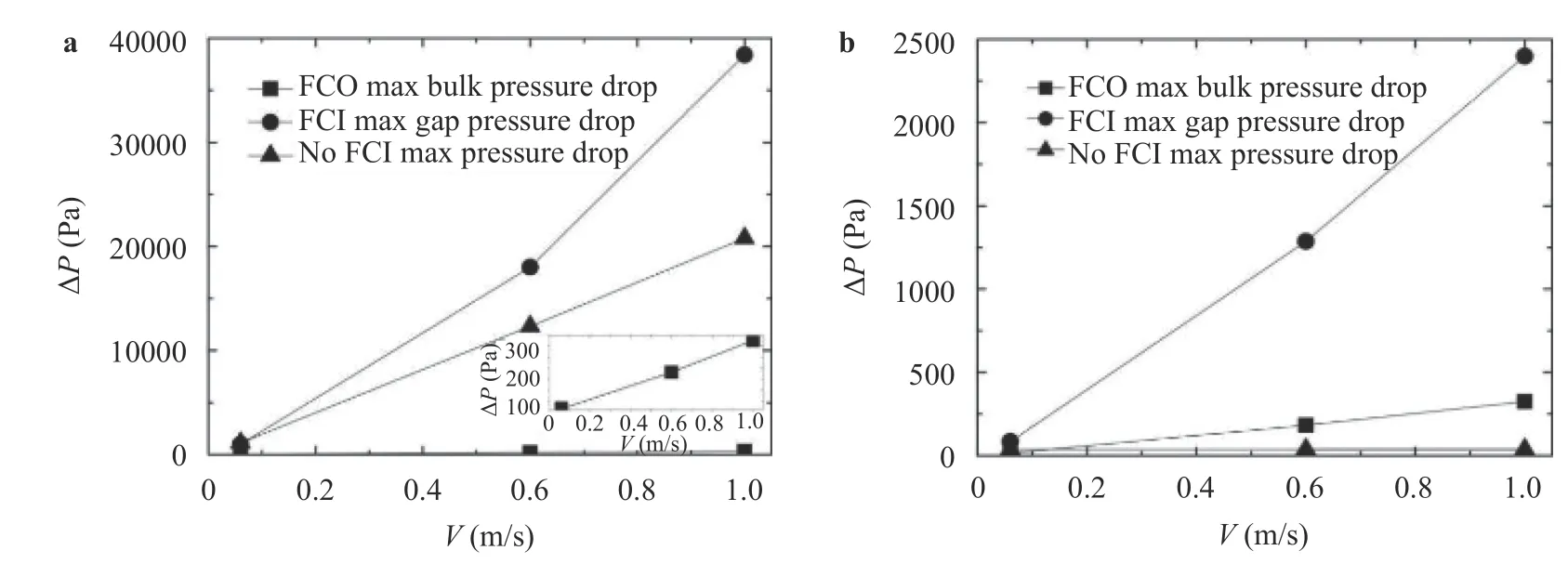
Fig. 5. Effect of the inlet velocity on the maximum pressure drop. a No coating boundary, b coating boundary
For investigating the DCLL channel flow and heat transfer characteristics, a mesh independence has been carried out firstlynumber , Ha =sults of the maximum velocity are shown in Table 2 within different spatial distributions,respectively, with 44 × 58 × 130, 54 × 68 × 140, 64 × 78 × 150, and 74 × 88 × 160 grids in the computational domain. It's observed that the relative error between Mesh 3 and Mesh 4 is as small as 0.027‰ from the Table 2, indicating that the numerical result is independent of the grid size. Therefore, in the premise of the computational efficiency, the spatial distribution in Mesh 3 will be adopted in the following study.
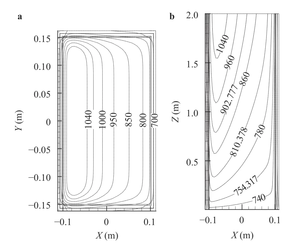
Fig. 6. Distribution of temperature (K) at no coating wall, FCI, Ra =6.3×10⁸ and B = 1 T. a Exit plane, b X-Z plane.
Figure 7 shows the local maximum, minimum Nusselt number and average Nu of the FW under B = 0.5 T for different heat source corresponding with Ra = 4.2×10⁸, 6.3×108,2.1×109, 7.5× 10⁹, 1.2× 10¹⁰and 3.5× 10¹⁰, respectively. The maximum Nu of the hot side increases with the increase of Ra rapidly. The minimum Nu keeps almost constant, which indicates the existence of an area where the convection is not influenced by Ra increasing.
Figure 8 shows the velocity profiles of gap flow under differ-
The MHD pressure drop with or without FCI varies with the inlet velocity for coating and general FW shown in Fig. 5. For walls with and without coating, the pressure drop increases exponentially with the inlet velocity increase, and the magnitude of increment at the bulk flow is slower than that at the gap flow.Under the coating wall condition, the influence of velocity on the maximum pressure drop is stronger than that of the magnetic field. When the velocity is 1 m/s, the maximum pressure drop of the gap flow is 63 times of that without FCI case. The use of the FCI does not significantly reduce the channel bulk flow pressure drops under coating wall condition.ent Ra for FCI and coating wall condition. The velocity gradually increase from the channel entrance 0.06 m/s to 0.12 m/s at exit but all maximum exit velocity is maintained at 0.12 m/s at various Ra. The strong “M” shape velocity distribution at entrance is easily observed.
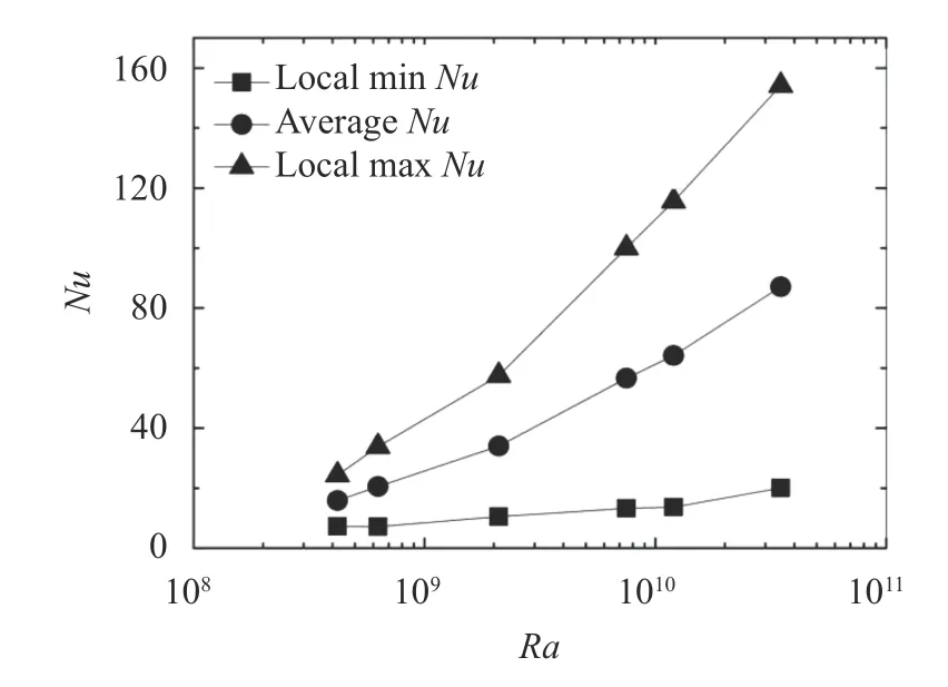
Fig. 7. Nu with different Ra
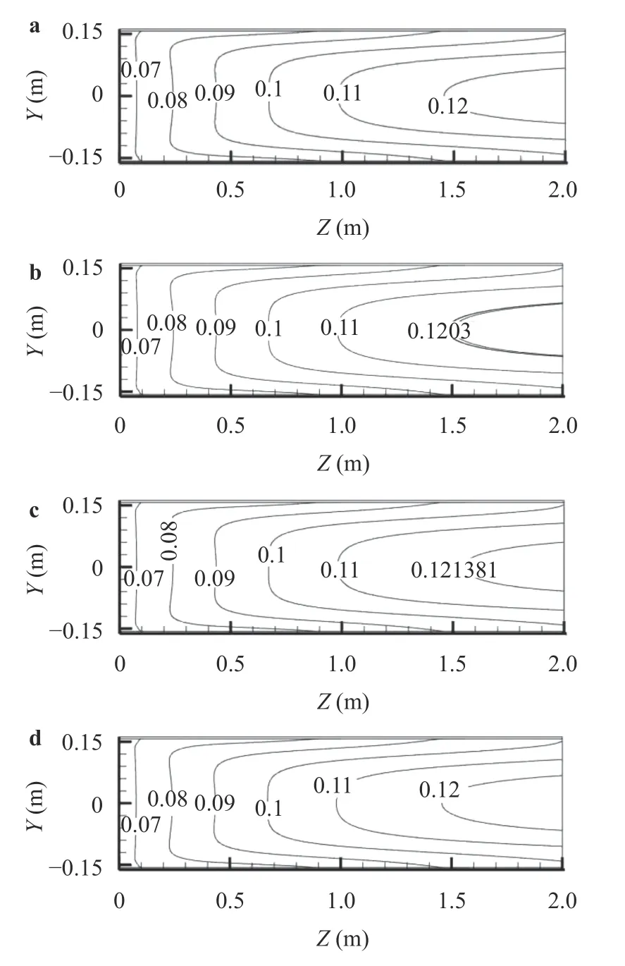
Fig. 8. Y section plane distribution of velocity (m/s) at gap for FCI and coating wall condition. a Ra = 2.1×10⁹, b Ra = 7.5×10⁹, c Ra =1.2×10¹⁰, d Ra = 5.6×10¹¹
To summarize, the key factors of DCLL heat transfer are Ra and coating boundary condition. The wall heat transfer is reduced by two times as opposed to the no coating boundary same as Ra. Based on the numerical simulation results, the Nu corresponding to the different Ra for different wall conditions are shown in Fig. 9. Due to the channel entrance velocity v = 0.06 m/s, the Re = 671, the convection effect is weak. And the Ra is far higher than that of Re, so the channel flow is dominated by buoyancy flow. From the coating and no FCI fitting curve, we can see that the Nu can be written as . By the equation, it is possible to predict the heat transfer characteristics of liquid metal within the DCLL at the coating boundary.
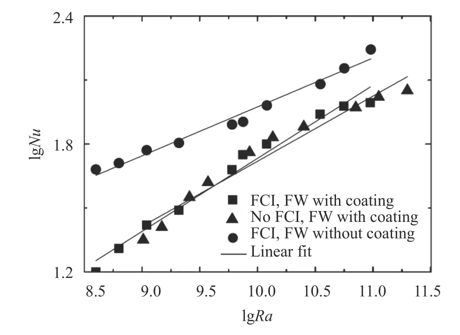
Fig. 9. Fitting curve lines with Ra.
In this paper, the influence of the coating boundary on the channel pressure drop and the FW heat transfer performance is investigated. The results are compared with the cases without coating and without FCI condition. The following conclusions are obtained: (1) By applying the NWNC on the inner surface of the FW, the maximum pressure drop of the channel can be effectively reduced to 40 times lower than that of no coating boundary in strong magnetic field. (2) The NWNC is added in the FW inner surface of DCLL channel, the hot side maximum Nu of coating boundary is declined by one times compared with that of the no coating wall case. (3) By fitting a large number of data, the Nu in DCLL channel without FCI and coating wall is written as.
Acknowledgement
This work is performed with support from the National Natural Science Foundation of China (Grants 11675077 and 51576208).
杂志排行
Theoretical & Applied Mechanics Letters的其它文章
- Mechanics of Tokamak fusion components
- Delamination strength of HTS tape under transverse tensile stress and its enhancement by using different Ag layer depositing temperatures
- Numerical study of MHD mixed convection under volumetric heat source in vertical square duct with wall effects
- Progress on design and related R&D activities for the water-cooled breeder blanket for CFETR
- Numerical methods for the magneto-mechanical coupling analysis of invessel components in Tokamak devices
- Progress on the ultrasonic testing and laser thermography techniques for NDT of tokamak plasma-facing components
