Considering for the blanket structure scheme of HCCB DEMO
2019-07-08ZhouZhaoZaixinLiXiaoyuWangXuerenWangKaimingFeng
Zhou Zhao*, Zaixin Li, Xiaoyu Wang, Xueren Wang, Kaiming Feng
Fusion Reactor Technology Division, Southwestern Institute of Physics, Chengdu 610041, China
Keywords:Helium cooled ceramic breeder (HCCB)Demonstration fusion power plant(DEMO)Blanket structure scheme Preliminary design and analysis
A B S T R A C TFor the solid blanket concept of helium cooled ceramic breeder (HCCB) demonstration fusion power plant (DEMO), a feasible blanket structure with configuration 2×X is proposed as considering relatively low temperature limit of neutron multiplier beryllium pebbles. Based on that, preliminary design for the typical blanket module of HCCB DEMO has been carried out and verified by thermal-hydraulic analysis and structural analysis. Furthermore, the specific relationship of maximum temperature depended on the surface heating of blanket key part first wall (FW) is also analyzed.
As well known, there is still a long way to go towards an economically competitive commercial fusion power plant, hence the demonstration fusion power plant (DEMO) is an indispensable step. The DEMO is aimed to demonstrate the safety, reliability and environmental feasibility of the fusion power plant,meanwhile to demonstrate the feasibility of the prospective economic evaluation of commercial fusion power plant [1]. In China, a concept design of helium cooled ceramic breeder (HCCB) DEMO, previously called as helium cooled solid breeder(HCSB) DEMO, is proposed by southwestern institute of physics(SWIP) at 2009 [2], which is mainly defined according to the blanket materials, the helium gas is used as the coolant (with operating pressure of 8 MPa and inlet/outlet temperature of 300/500 °C) and also as the tritium purge gas (with inlet pressure of 0.12 MPa and outlet temperature of 450 °C [3]), the solid ceramic Li4SiO4pebbles and the metal beryllium (Be) pebbles are selected as tritium breeder and neutron multiplier respectively, and the reduced activated ferritic/martensitic steel(RAFMs) is choose as the structure material.
Blanket is the key component, in the view of structure design,the main difference between the current international thermonuclear experimental reactor (ITER) [4] and the future DEMO as well as including the China fusion engineering test reactor(CFETR) [5], is the blanket modules. As considering the issue of tritium self-sustaining, the blanket modules in the vacuum vessel of DEMO will be all the type of tritium breeding, instead of 440 shielding blanket modules in ITER except only 3 small tritium breeding test blanket module (TBM) ports [6]. For tritium breeding blankets, either the solid concept or the liquid concept[7], both need carefully to consider and choose the feasible blanket structure scheme, which is a key initial step in the blanket design for the fusion DEMO.
The helium cooled ceramic breeder (HCCB) solid blanket concept for TBM of ITER has been researching and developing at SWIP of China as well as in European Union (EU) for many years [8-11], and the box structure with sub-breeding cells should be a practical blanket module scheme. It can be generalized to perform concept design of HCCB DEMO blanket based on this box structure scheme.
On the whole, HCCB DEMO blanket module mainly includes the outside component blanket box (it is made of FW,top/bottom caps and back plates system) and the inside subbreeding cells which is separated by grid plates that is also used to strengthen the blanket box under in-box loss of coolant accident (LOCA). In addition, the manufacturing assembly of blanket module is based on that of TBM in the several welding processes that require post-welding heat treatments at high temperature, however which has much higher than the temperature limit 650 °C of Be pebbles [12], therefore the Be pebbles will be filled and packed from outside by drilling local holes after assembly welding and heat treatments [13]. As there is no feasible to pack Be pebbles from the front side of FW (facing plasma surface is requested not to have local holes and welding seams) and the rear side of back plates system (complicated multilayer plate-cavity structure), so to fill and pack Be pebbles is only from the top/bottom caps or lateral left/right sides of FW, at the same time, considering each sub-breeding cell of blanket module is isolated and independent closed, thus it is derived that the feasible box structure configuration with maximum sub-breeding cells for every HCCB DEMO blanket module will be: 2×X, as shown in Fig. 1.
Due to the blanket module located at the plasma outboard equatorial plane of HCCB DEMO is needed to withstand the maximum neutron wall loading and surface heating, therefore to carry on the design and analysis for it has a typical significance.Figure 2 is the simple schematic diagram of outboard typical blanket module; its plasma configuration shape (with 12° toroidal sector) is according to the parameters of Table 1 from Ref. [2].
Because of the need to meet tritium self-sustaining, it is necessary as possible as to increase the size of every HCCB DEMO blanket module and to fill more sub-breeding cells. Then how to determine the directional critical dimensions of blanket module? For the typical blanket module of HCCB DEMO as shown in above Fig. 2, its radial critical dimension is preliminarily identified as ~800 mm according to the relevant references on the neutronics TBR requirement of HCCB DEMO [14]. To determine its toroidal critical dimension is on the basis of coolant helium pressure drop requirement, that of a whole blanket module is below the limit 0.4 MPa that corresponds to ~5% of the coolant helium nominal pressure 8 MPa according to which the maximum admissible compression ratio of 1.05 must not be exceeded[15]. The pressure drop of blanket module is mainly concentrated in the helium cooling channels of blanket key part first wall (FW) (in order to satisfy the surface heat flux of 0.43 MW/m2and neutron wall loading of 2.3 MW/m2of HCCB DEMO, it is required the coolant helium with velocity ~75 m/s [16] in every cooling channel of FW), cooling plates of sub-breeding cells and coolant manifold (MF) system of back plates; As the preliminary design, it is set the pressure drop limit of each helium cooling channel of FW is nearly ~0.1 MPa and then to determine the toroidal critical dimension, which is determined to be ~2070 mm by the thermal-hydraulic analysis (using commercial program ANSYS/CFX) with the simple analysis model as shown in Fig. 3; Its poloidal critical dimension is based on the strength requirement under in-box LOCA accident by structural analysis, here firstly assumed to be ~705 mm and that will be verified in the next step of work. In summary, the initial size parameters of typical blanket module is 800 mm (R) × 2070 mm (T) × 705 mm (P) as shown in above Fig. 2, and with assumed 2×11 configuration.
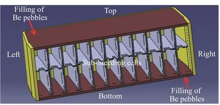
Fig. 1. 2×X box structure configuration for HCCB DEMO blanket modles
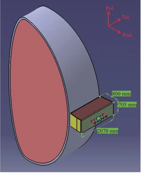
Fig. 2. Schematic diagram for the typical blanket module of HCCB DEMO
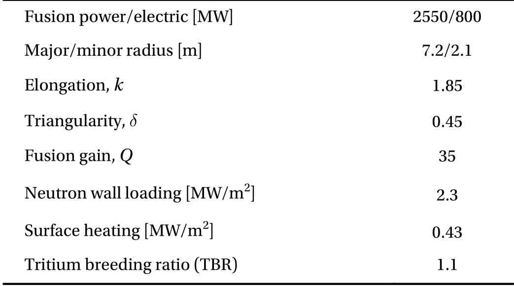
Table 1 Preliminary design parameters of HCCB DEMO
Based on that, the MF system of back plates and coolant flow diagram for the typical blanket module is designed preliminarily,the detail as shown in Fig. 4, where the MF 1 is used to distribute the coolant from pipe inlet of helium cooling system (HCS) to 38 internal cooling channels of FW through the left and right sides,the MF 2 is used to collect the coolant from FW and distribute it to the inside stiffened grids of blanket box and top/bottom caps,and then by the MF 3 the coolant is distributed to the cooling plates of sub-breeding cells, lastly the coolant is converged to MF 4 and flowing into the HCS by outlet pipe.
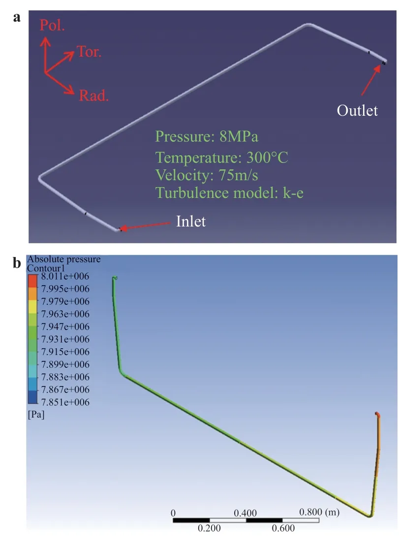
Fig. 3. Thermal-hydraulic analysis model and pressure distribution for the single helium cooling smooth channel of FW. a Analysis model, with cross section dimensions of 13.5 mm×14 mm and 3 mm radius corners. b Pressure distribution, pressure drop of ~ 0.09 MPa between inlet and outlet
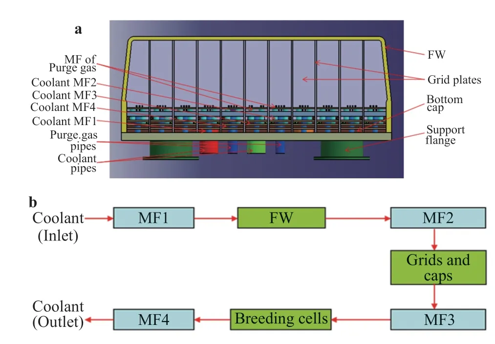
Fig. 4. Back plates system and coolant flow diagram for the typical blanket module. a Back plates system. b Coolant flow diagram.
As the coolant for the key thermal-structural part FW of blanket is distributed by MF 1, its function is very important, and the structure characteristics of MF 1 basically decide the overall design direction of the manifold system. Fig. 5(a) is the internal fluid domain design of coolant MF 1 with thickness of 26 mm,which is a center symmetric structure, each side having 19 branch channel inlets of FW on the left and right, and the total helium inlet mass flow rate is ~3.4 kg/s according to the required helium velocity is ~75 m/s for every branch channel of FW; Fig. 5 b) shows its thermal-hydraulic analysis result of helium velocity distribution, it can be seen the mass flow rate uniformity for the branch channels of FW is well good, with the flow uniformity of ~97% (Max 8.721×10⁻²kg/s - Min 9.032×10⁻²kg/s).
The surface heating of FW is a key input parameter to the thermal-hydraulic design of DEMO blanket, and considering the maximum allowable temperature of blanket structural material RAFMs (its thermal conductivity seen in the following table 3) is only 550 °C [3], therefore it is necessary to analyze the specific relationship of maximum temperature depended with surface heating and as the design reference. Figure 6 is a corresponding simple thermal-hydraulic analysis model of FW with thickness 38 mm, which only includes two layers cooling channels of FW flowing opposite direction each other, and the mass flow rate of inlet a and inlet b (8.745×10⁻²and 8.721×10⁻²kg/s) are based on the thermal-hydraulic analysis results of coolant MF 1 above mentioned. At the same time, the influence of radial power density deposition in FW body under neutron wall loading of 2.3 MW/m2as shown in Fig. 7 from the reference [14], also is analyzed.
It can be seen that from analysis results of Fig. 8, in the case of to keep inlet a and inlet b mass flow rate invariant (close to 75 m/s) thus limit the pressure drop of FW channels to ~0.1 MPa,the maximum temperature of FW both shows an obvious linear increase with increasing of surface heating whether to consider the neutron wall loading (power density) or not, and the temperature rise is ~54 °C between them. Under the condition of neutron wall loading 2.3 MW/m2, the surface heating 0.43 MW/m2already is close to the limit value because of the safety margin temperature only has 16 °C. It also indicates that ~75 m/s helium velocity in every cooling channel of FW is reasonable to satisfy both the surface heat flux of 0.43 MW/m2and neutron wall loading of 2.3 MW/m2for HCCB DEMO.
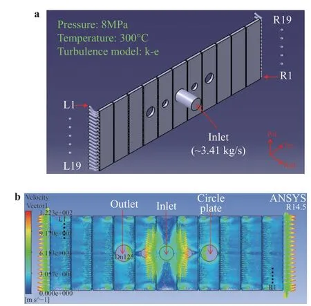
Fig. 5. Helium domain model and velocity distribution of coolant MF1. a Helium domain model. b Helium velocity distribution.
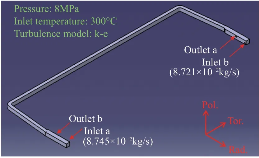
Fig. 6. Double layers thermal-hydraulic analysis model of FW
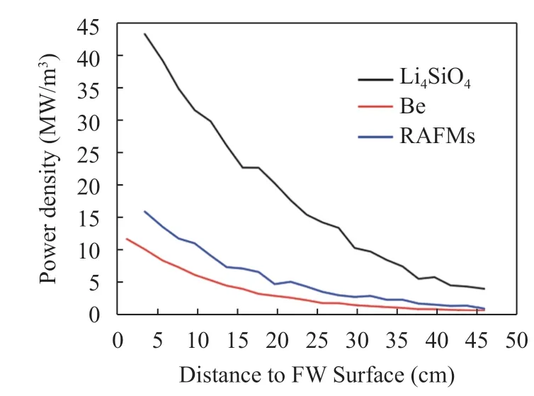
Fig. 7. Radial power density deposition in blanket materials under neutron wall loading of 2.3 MW/m2
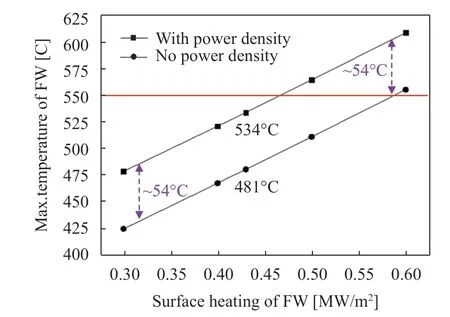
Fig. 8. Maximum temperature depended on surface heating of FW
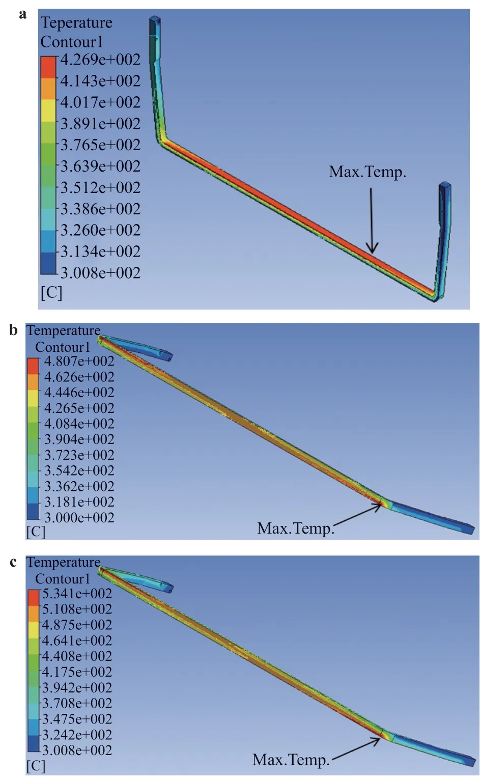
Fig. 9. Temperature distribution of double layers FW. a Under neutron wall loading of 2.3 MW/m2. b Under surface heating of 0.43 MW/m2. c Under neutron wall loading of 2.3 MW/m2 and surface heating of 0.43 MW/m2.

Table 2 Design criteria for prevention of P-type damage (elastic analysis)

Table 3 Thermo-mechanical properties of RAFMs CLF-1
Meanwhile, comparison the different thermal loading conditions, as shown in Fig. 9, which can be clearly found that the surface heating plays an obvious dominant role in the temperature distribution of FW, rather than the neutron wall loading.
The blanket box is the primary structure confinement of the coolant helium, breeding material and tritium, therefore its integrity is paramount from the safety point of view both during normal operation and accidental condition. Therefore the structural integrity verification against P-type (the detail design criteria for primary stress listed in Table 2) for the blanket box has been analyzed firstly by finite element (FE) elastic method (using commercial program ANSYS/Mechanical Model) with regards to the criterion RCC-MR 2007 [17], under the conditions of normal operation (Category I) and in-box LOCA accident(Category IV), respectively. In the analysis, thermo-mechanical properties of structural material RAFMs CLF-1 [18] are used, as listed in table 3, and the reference/environment temperature is set to conservative 500 °C.
The blanket box assembly is consisted of FW, caps, grid plates and back plate system, which is very complicated especially the back plate system (seen above Fig. 4) but with an approximate symmetrical structure feature. Therefore in the structural analysis for blanket box, the simplified 1/4 symmetry geometric model is adopted, as shown in Fig. 10(a), and the boundary conditions include 3 single direction fixed constraints (x, y,and z) respectively for 2 symmetry surfaces and the end surface of support flange of blanket box. The corresponding FE mesh model of blanket box is shown in Fig. 10(b), there are total about 1.54 million mixed solid elements (SOLID 186 and 187), and where the hexahedron and prism types (SOLID 186) are dominant.
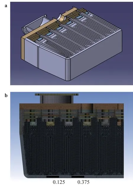
Fig. 10. Simplified 1/4 structural analysis model and FE mesh model for blanket box. a Geometric model, b FE mesh model.
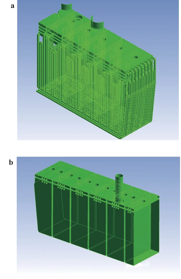
Fig. 11. Pressure loads of 1/4 blanket box analysis model. a Coolant of 9 MPa, b purge gas of 0.6 MPa.
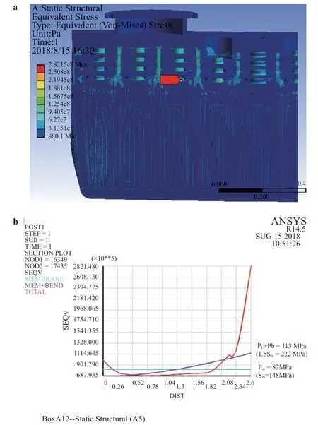
Fig. 12. Equivalent stress of blanket box under normal operation. a Stress distribution, b linearized stress results.
The blanket box is a pressure component, the pressure is the most important and dominant load in structural analysis for prevention of P-type damage. Under normal operation, there are two kinds pressure load of blanket box including the design pressure of 9 MPa for the coolant surfaces and 0.6 MPa for the purge gas surfaces [19], the detail pressure loading of 1/4 analysis model is shown in Fig. 11.
Equivalent stress analysis result of blanket box under normal operation is shown in Fig. 12(a), it is observed that the global equivalent stress is not high, the maximum stress is 282 MPa that locates in the root position of stiffening column of coolant MF 2,and its linearized stress results, as shown in Fig. 12(b), can meet well the material allowable stress requirements Sm/1.5Smat 500 °C (148/222 MPa) based on the criteria of RCC-MR 2007.
In case of in-box LOCA accident, the helium coolant will mix up with tritium purge gas, then all the blanket box inner surface pressure of purge gas part rises up to the peak value about 8 MPa with same that of coolant. And the blanket box shall be designed to withstand this over pressurization. However, in the DEMO blanket design, it could be considered to use the rupture disk and to limit the peak of pressure in the blanket box, thus allowing to a significant lower design pressure for the blanket box itself during the LOCA [20]. By this opinion, here it is preliminarily assumed the peak pressure down to 4 MPa, and its result the primary stress of blanket box will be able to meet the requirements of design criteria RCC-MR 2007 under in-box LOCA accident, the detail stress as shown in Fig. 13.
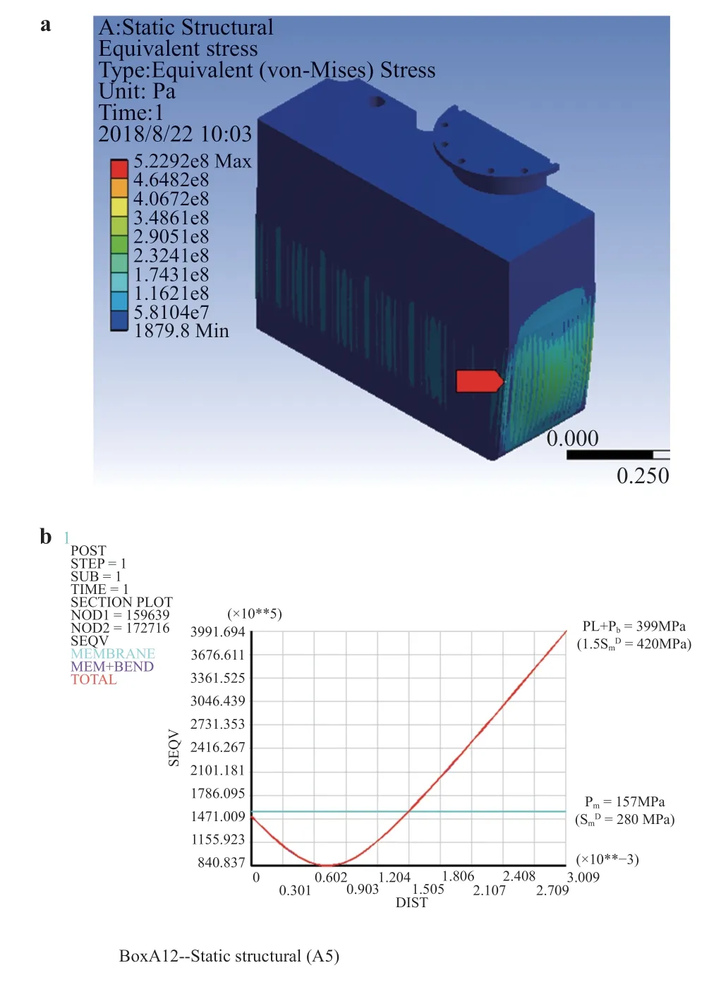
Fig. 13. Equivalent stress of blanket box under in-box LOCA accident with peak pressure 4 MPa. a Stress distribution, b linearized stress results.
In summary, due to the issue of tritium self-sustaining, the blankets in the vacuum vessel of DEMO (including the CFETR)are all the type of tritium breeding, which requires considering and choosing the feasible structure scheme of blanket in overall.For the solid blanket concept HCCB DEMO, a feasible blanket module scheme is the box structure of sub-breeding cells with configuration 2×X, as considering the relatively low temperature limit of Be pebbles. Based on that, the main structure box of typical blanket module of HCCB DEMO has been designed preliminarily, and the further thermal-hydraulic analysis and structural analysis have verified its dimension size and structure configuration 2×11. At same time, the specific relationship of maximum temperature of FW depended on the surface heating is analyzed in detail.
Acknowledgments
This study is supported by the National Special Project of China for magnetic confined nuclear fusion energy(2015GB108004).
杂志排行
Theoretical & Applied Mechanics Letters的其它文章
- Mechanics of Tokamak fusion components
- Delamination strength of HTS tape under transverse tensile stress and its enhancement by using different Ag layer depositing temperatures
- Numerical study of MHD mixed convection under volumetric heat source in vertical square duct with wall effects
- Progress on design and related R&D activities for the water-cooled breeder blanket for CFETR
- Numerical methods for the magneto-mechanical coupling analysis of invessel components in Tokamak devices
- Progress on the ultrasonic testing and laser thermography techniques for NDT of tokamak plasma-facing components
