Investigation on structural component behaviours of double bottom arrangement under grounding accidents
2019-03-07AdityaRioPraowoTeguhMuttaqieJungMinSohnBangunHarsritanto
Aditya Rio Praowo*, Teguh Muttaqie, Jung Min Sohn, Bangun I.R. Harsritanto*
a Department of Mechanical Engineering, Universitas Sebelas Maret, Surakarta 57126, Indonesia
b Agency for the Assessment and Application of Technology, Jakarta 10340, Indonesia
c Department of Naval Architecture and Marine Systems Engineering, Pukyong National University, Busan 48513, South Korea
d Department of Architecture, Universitas Diponegoro, Semarang 50275, Indonesia
Keywords:Bottom raking Double hull tanker Oceanic rock Structural crashworthiness Stress-strain responses
ABSTRACT Marine accidents have caused immense casualties on various parties in shipping and shipbuilding industries, including financial and structural losses. This situation makes ship accident becomes a critical subject in naval architecture and marine structures, as it needs continuous assessment and investigation to broaden insight and data of collision and grounding phenomena. The paper aims to investigate structural conditions of a ship arranged by double hull system under accidental scenario, namely ship grounding. Fundamental concept of structure-rock interaction in poweredhard grounding is adopted to design impact configuration for calculation using finite element (FE)simulation. Involved entities are defined as the structure represented by tanker vessel, and oceanic rock is deployed as the indenter in analysis. Calculation results indicate that the crashworthiness capability of structural part strengthened by longitudinal girder is higher than other selected locations on the structures against rock penetration. Localized flooding of storage oil may occur during raking damage is formed on structural part between two girders.
1Introduction
Since the beginning of human history, trading activity across islands has been conducted by men using water transportation modes, namely ship. Development of public society and trading regulation influences trends of ship structures as it needs to carry various cargoes, such as industrial product and raw material. Dangerous and hazardous cargoes are also transported using ship considering reasonable delivery cost and sailing time.This situation makes structural arrangement for these cargo types is rigorously developed, which one of the main backgrounds is massive oil spill disaster of the Exxon Valdez in Alaska due to impact between ship structure and oceanic object [1, 2].Therefore, attention is given now to investigation of structural performance against marine accident with impact characteristic,such as collision and grounding. This effort requires large amount of scholars' involvement from wide subjects as remarkable casualties also affect industrial financial, human safety and marine environments [3-9]. Still, the key to predict all of these losses is condition of ship structure which has to be assessed continuously due to nature of accidental events is large scenario models. They will certainly produce different pattern depends on encountered impact scenario. In case of grounding, impact occurs in forms of structure-rock interactions where different penetration style has very high significance on the structure. The penetration model can be used to evaluate structural performance during the interaction, and to assess its condition on postaccident analysis. Numbers of crashworthiness parameters are deployed in pioneer studies, such as energy, force and damage.Besides these, structural behaviours under impact are also vital subject which can be used as references to predict structural durability after accident. Behaviours of the double bottom part themselves can be classified into several groups depends on investigation scale, e.g. displacement of local members which it is found that scant observation in this theme can be taken as research opportunity for the next work in grounding phenomenon.
Considering the initial discussion, this work is conducted to investigate of structural conditions under accidental structurerock interaction, i.e. grounding. A tanker structure and oceanic rock are modelled using configuration and setting in numerical method as the deployed geometries for a series of finite element simulation. Results related to structural contours under the impact phenomenon are presented to quantify the progressive behaviours on the global structure, which is followed by observation on dynamic behaviour of the local members on double bottom structures subjected to effect of grounding accidents.
2Pioneer works in grounding phenomenon
Researches have been conducted by taking grounding as reference of marine disaster model to various ships, including passenger ship, tanker vessel and container carrier. Several methods are taken into account, such as rapid prediction of internal energy of the ship structure using empirical-theoretical formula[10]. Empirical approaches has developed sustainably since firstly introduced by Minorsky [11] for high-collision energy.Woisin [12] modified the formula to be more suitable in low-energy scenario. Other scholars, such as Lu and Callidine [13] and Paik [14] also improved the perspective of the basic form by involving material factors besides geometry characteristics. Advance improvements of computational technology that occurred since the end of 90's, allows researchers to idealize large scale experiments [15, 16] using numerical method, such as finite element (FE). Other previous methodologies are still used for calculation which often deployed as benchmark particulars.Several works which adopt this concept are presented by Prabowo [17-19], AbuBakar and Dow [20], and Alsos et al. [21].Application of the FE approach to specifically quantify material effect under grounding and other impact forms is addressed as geometry and material which are two main elements in numerical modelling and analysis. Related to these subjects, Marinatos and Samuelides [22] defined a set of physical and numerical parameters which directly contributes to responses of ship structures under accidental loading. In other work, probabilistic assessment to study annual risk of collision and grounding with RoRo passenger ferry is designated as a subject [23]. A notable result of this research stated that capsize of the vessel after experiencing such impact phenomena is the main factor of the high annual risk and casualty.
3Theoretical basis of structural damage under raking
3.1Simonsen model for global deformation [24]
It is well known that structural arrangement of double hull vessel consists of shell element which forms an assembly, such as double bottom structure. Therefore, it is convenient to assume that deformation shell on both bottom and inner bottom plates as global deformation mode. During interaction with obstruction (it is defined as conical rock), all elements attached to the shell will consistently take part in process of plate deformation. Simonsen presented an idea to show two deformation types of double bottom structure, i.e. with and without fracture (see Fig. 3 in Ref. [24]). Concept of deformation mode is defined as a material element (plate) undergoes bending, stretching and fracture. The dissipated energy will directly correlated with material fracture and deformation extent.
3.2Hong-Amdahl concept for girder deformation [25]
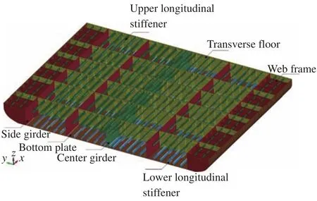
Fig. 1.Idealized model of the double bottom structure and its structural components.
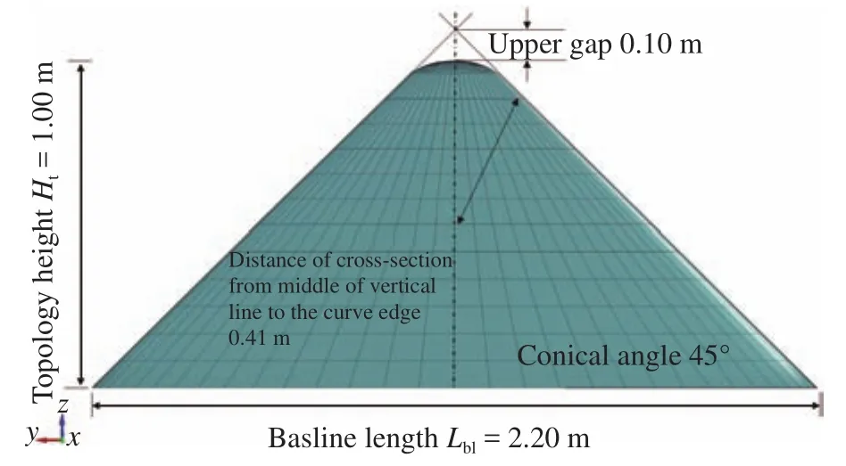
Fig. 2.Configuration of the rock indenter for structure-rock interaction calculation.

Fig. 3.Fundamental illustration of the grounding accidents on the tanker.
Deformation pattern of girder is complex which involves bending, stretching, compressing and shearing. The proposed idea is fundamentally adopting paper folding mechanism, which has advantage that the top edge of the girder (see Fig. 14 in Ref.[25]) displaces in certain distance to horizontal direction. There are three main elements in this assumption, such as 2H is the vertical crushing distance, 2L is the horizontal crushing length,andis the transverse crushing angle. The cross section of the girder then forms Z shape in the ultimate state with assumption that localized deformation occurs in the shaded area, and in this location also initiation of a new fold is exist from one side to the other. It was concluded that proposed mechanism has good agreement with the final deformation pattern produced by FE analysis.
3.3Liu-Soares approach for evaluation of web girder [26]
There are two ways for the web girder to dissipate the energy,i.e. rotation of the plastic hinge and member tension on the plastically deformed zone. The previous assumption of Hong and Amdahl regarding the girder folding is developed by classifying two parts of this phenomenon, such as plastic deformation and elastic buckling zone. However, the lowest part of the web girder is assumed to be deformed due to elastic buckling which absorbed almost zero energy (see Fig. 3 in Ref. [26]). To keep simplicity of the theoretical method, calculation of the slope on the elastic buckling zone is neglected as it gives insignificant effect on the folding length.
3.4Summary and comparison
Based on three pioneer works related to damage investigation on double bottom structure, it is obtained that the initial study conducted by Simonsen presented global deformation of the structure against rock impact. It was assumed that bottom plate experienced plastic deformation under longitudinal impact, known as raking, which prediction of the membrane straining was presented in a part of this study. On the developed study, observation on girder is taken as interesting subject,where Hong and Amdahl investigated damage in this member subjected different angle in raking. Empirical expression representing relations between vertical crushing depth and crushing depth of the indenter was introduced. Meanwhile, the subject in study by Liu and Soares focussed in quantifying behaviours of the girder subjected to vertical impact, including their progressive stage. The current work will investigate by collaborating these three concepts, which local members will be expanded to girder and plate in same work. Several other members will also be discussed in this work. Longitudinal grounding mode, or powered-hard grounding is adopted, while progressive stages of their contour response and displacement behaviour on the ship structures will be investigated later.
4Modelling and calculation configuration
4.1Structure and indenter geometries
The idealized double bottom structure (Fig. 1) is built based on a chemical tanker with length L = 144 m, breadth B = 22.6 m,and height H = 12.5 m, using FE method. A deformable shell element is deployed to model a number of structural components,such as plating, stiffener, girder, frame and floor. Element formulation is taking integrated version of the Belytschko-Tsay into account to avoid hourglass and shear locking phenomena due to high nonlinearities during structural crushing. Since high intensity of structural damage is expected during structure-rock interaction, it is necessary to define failure criterion for the ship structure. Under impact circumstance, failure is assumed as state of the applied material exceeds the designated strain limit.The applied material incorporated by strain characteristic (see the computational formulation[27], strain-related terms' definition[28], for example of material model in impact analysis[29]),i.e. plastic kinematic is chosen to be applied on the structure.Considering material imperfection due to aging and its effect to material performance, low value of the strain failure based on finding of Amdahl [30] is inputted to the material configuration as summarized in Table 1.
Entity of the indenter is required to fulfil structure-rock interaction in numerical simulation. Characteristic of oceanic rock is adopted for this work with assumption that dominant mineral composition of the rock is plagioclase f. This mineral type is ex-ist in formation of oceanic rock together with pyroxene and olivine. Material input for the indenter is presented in Table 2. It is also assumed that the deployed rock is very hard with low possibility to deform. This criterion is included in order to properly model crushing of structural components, and focuses the deformation pattern only on the structure. Therefore, solid-rigid material model is implemented on the indenter. Topology of the rock is idealized as conical shape (Fig. 2) with moderate angle.
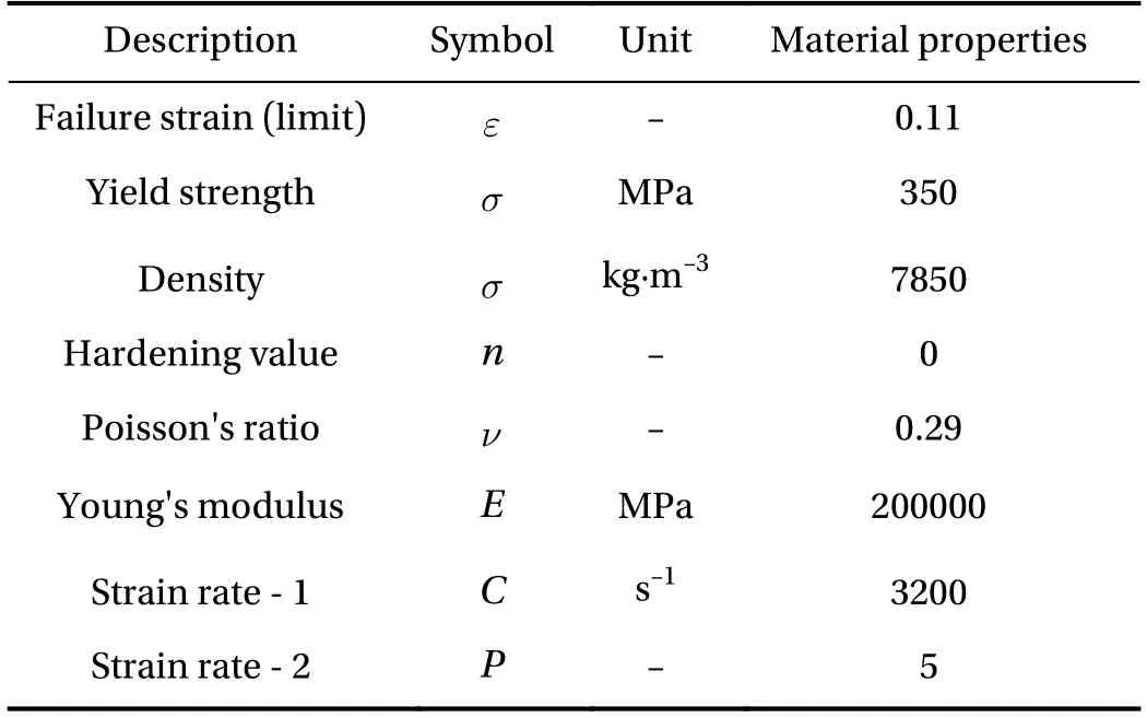
Table 1Configuration of the applied material on the double bottom structure.
4.2Scenario preparation
Grounding is designed as interaction between tanker structures and oceanic rock in this work with concept of the poweredhard grounding is adopted (Fig. 3). The powered characteristic is a condition when the ship is in their operational modes or moves in certain velocity. Therefore, the applied velocity in grounding scenario is assumed to be in their operation with value V = 10 m·s-1. There are three designated contact targets(Table 3), namely center girder, side girder and bottom tank(space between girders). This measure is considered to observe different damage modes on the structure, i.e. one with longitudinally strengthened by girder so that girder crushing is also possibly observed, and other one is pure plate rupture due to contact with the rock. The designed dynamic-nonlinear scenarios will be subjects of numerical calculation using FE explicit codes ANSYS LS-DYNA. Time calculation is idealized to be very short with t = 0.4 s to match with characteristic of impact load and keep stability of the calculation.
5Results and discussion
5.1Impact on girders
Tendency of the structural components is described based on displacement response on different directions according to the Cartesian coordinate. The description is presented in graphs with x-axis stands for ratio of longitudinal displacement of the indenter X and length of idealized double bottom structure L. On the other hand, the y-axis represents displacement response which also describes non-dimension value. The value is accounting to the observed displacement direction. As shown in Fig. 4, the displacement response is in longitudinal direction.Thus, the ratio is composed based on displacement of the structural components x and length of idealized double bottom structure L. From the same figure, the lower stiffener was displaced significantly compared to other components during impact to the center girder. This tendency is followed by other longitudinal component, namely center girder with ratio value approximately 0.0012 m. Meanwhile the bottom plate which exists in xy plane was also displaced but less than the mentioned components. As for the transverse direction, the bottom floor did not show significance, and had small fluctuation. It is also observed that other components, such as side girder, tank top, transverse frame and upper stiffener were not affected nor contacted with indenter during impact.

Table 2Material characteristic for the indenter.
Other form was recorded during observation on the displacement response of y-axis (transverse direction) which the most significant response was experienced by the main target i.e. center girder. From the waving tendency as found in Fig. 5, it is concluded that the girder flapped on direction of starboard and portside of the ship as deeper penetration occurred on the double bottom. Displacement response of this direction is larger than the longitudinal direction, which the highest value reaches 0.0015. Other components show inactive tendency where no response is obtained during raking. Only minor increment with value less than 0.0001 was observed on the lower stiffener. It is predicted that displacement on the y-axis occurred only on the center girder as this component is not entirely crushed in vertical direction. If higher indenter was deployed, there will be no displacement of the center girder in the y-axis as the girder will be cleanly crushed during penetration by the rock.
As for the displacement response on the vertical direction (zaxis) presented in Fig. 6, three structural components showed incremental tendency, such as center girder, lower stiffener and bottom plate. Response values of these components show that the most significant response occurs in this direction. This phenomenon took place as the lower part of the indenter was crushing the three components and pushed them on the direction of the indenter's penetration. Since the indenter has conical topology, the pushed component moved to vertical direction due to influence of moderate conical angle. If the indenter has very steep characteristic (conical angle is closer 90°), the displacement response will be dominated by fluctuation in longitudinal direction.
It is realized that high structural crushing was taking place during powered-hard grounding or so-called raking which directly affected structural behaviours. Before structural components experience ultimate state of failure, material will undergo thickness reduction. This process progressively occurred on the structure until finally connection of two or more components failed. As observed in Fig. 7, the red-mark area represents parts that heavily affected by thickness reduction. Relation between this phenomenon and failure is successfully verified as the mostinfluenced parts of structural components were located very near with failure spot.

Table 3Designed grounding scenarios for the current work.
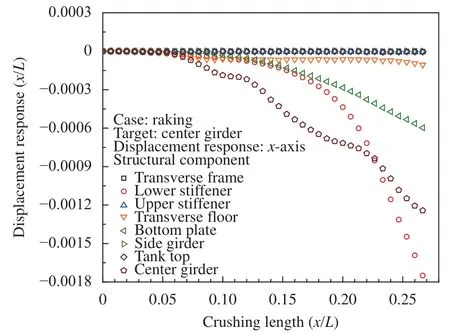
Fig. 4.Displacement characteristic during impact to the center girder: in x-axis.
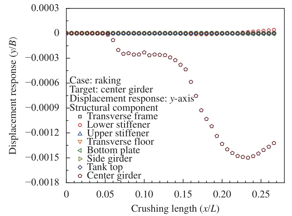
Fig. 5.Component displacement in y-axis during impact to the center girder.
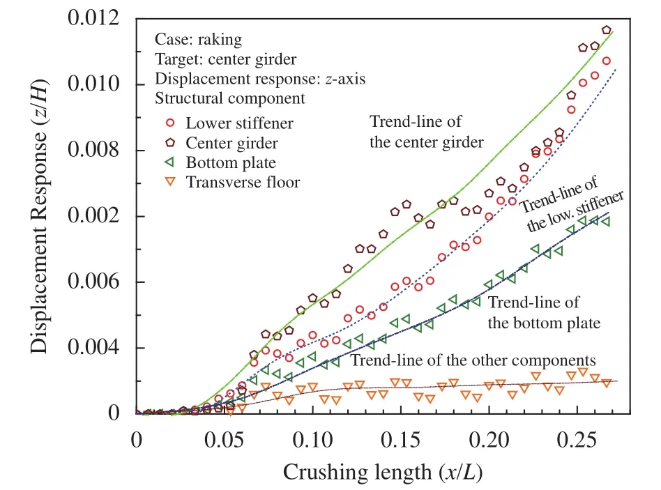
Fig. 6.Displacement of structural components in z-axis during impact to the center girder.
Structural response under raking is also quantified in terms of the plastic strain (Fig. 8). The contour value is equal to the applied failure strain. It can be seen that distribution of the strain on the initial contact between structure and rock occurs from the bottom plate on the lowest component of the structure to the vertical direction. The green spot on the double bottom was forming triangle contour which was match with conical topology of the indenter. This contour developed to the longitudinal direction, and caused strain on bottom plate, lower stiffener and girder consecutively. In the end of penetration, it was obtained that the second transverse floor was breached, and crushed lower part of the bottom structure. Therefore, it was safe to assume that there are four bottom tanks will spill oil and/or waste to the sea. Significance of the effective stress in Fig. 9 also indicates that hot-spot on the initial contact appears by forming triangle contour. This contour is distributed vertically until upper part of the double bottom, such as tank top, and moderate stress contour was transferred to the next compartment through the lower stiffener. As deeper penetration took place, higher stress contour expanded to the second floor and compartment. High contours on the girder during t = 0.2 got reduced and more stress appeared on the third floor. In the end of contact, high contours were observed on the second floor and bottom plate on the second compartment. It was also noted that quite high contour was distributed on the connection between the lower stiffener and the third transverse floor.
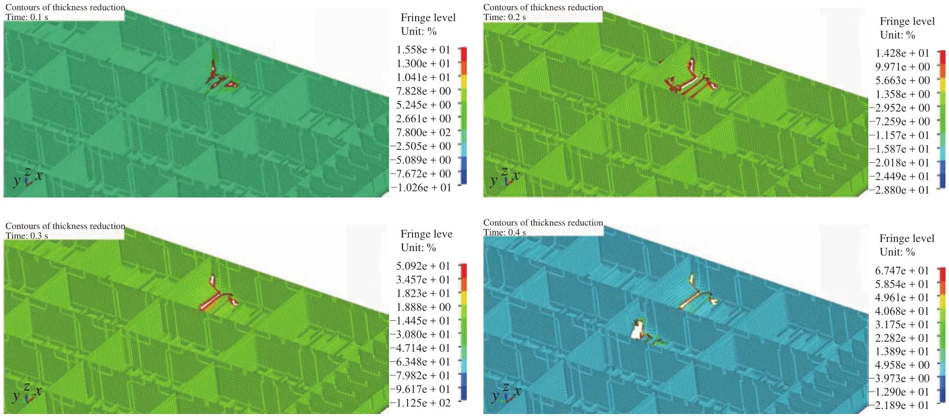
Fig. 7.Thickness-reduction contours of the double bottom under raking.
Besides raking on the center girder, influence of the structure-rock interaction to other longitudinal target is addressed to the side girder. Based on illustration in Fig. 10, it is found that the bottom plate dominates displacement response on the longitudinal direction. This tendency is followed by side girder,lower stiffener and transverse floor with much smaller value.Components near the side girder which has relative wider space between the stiffeners than the center girder, did not experience significant displacement while the lowest component was displaced into longitudinal direction. Occurrence of this phenomenon is predicted due to difference of the stiffener spacing surrounding the girder. Significance of the side girder in experiencing displacement is shown in Fig. 11 which describes response in transverse direction (y-axis). Tendency in this figure indicated that the deformed girder was flapping similar with the center girder but in much smaller value. Other observed behaviour is the lower stiffener which was quite deformed to the yaxis. Based on this result, it can be quantified that more narrow the distance between the stiffeners, displacement response will tend higher in longitudinal direction. Meanwhile, more space provided between stiffeners will cause mode displacement on the transverse direction. This conclusion is taken with assumption that the structure is against raking phenomenon in sailing.Furthermore, more space between stiffeners on the structural design is affecting displacement response of the bottom plate on the vertical axis (Fig. 12). Since flexural rigidity of bottom plate is reduced due to farther distance of the stiffeners, this component was displaced more significant than the girder.
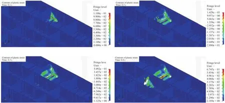
Fig. 8.Strain contours during impact to the center girder.
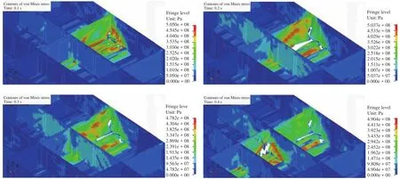
Fig. 9.Distribution of the effective stress (von Mises) near the center girder.
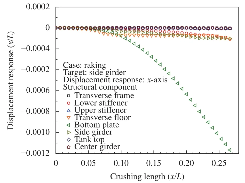
Fig. 10.Longitudinal displacement of the structural components under impact to the side girder.
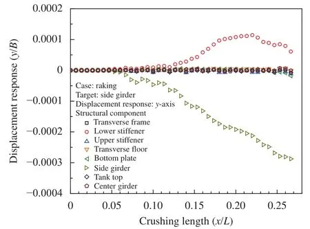
Fig. 11.Transversal displacement of the components during contact to the side girder.
In terms of the response contours (Fig. 13), the strain indicate similar contour on the transverse floor (the first and second floors) and girder. Nevertheless, it is clearly noted that less number of the lower stiffener was involved during interaction with the conical indenter. Red contour of the strain on the girder concludes that this element will fail soon if an indenter with larger diameter (in conical topology) was used in the calculation. Discussion on the contour also considers effective stress which in impact to the side girder, it is noted that more elements of the bottom plate on the first compartment was crushed. Contribution of the stiffener in strengthening the bottom plate during raking is vital since wider the opening on the double bottom structure will cause more damage to the environment due to oil spill.Stress distribution on the third compartment is also spotted through a stiffener instead of two stiffeners as experienced on near the center girder.
5.2Impact on bottom tank
The other target, namely space between girders (bottom tank) is selected to observe significance of structural geometry against raking phenomenon. In this location, as observed in Fig.14, the displacement response on the longitudinal direction is dominated by the bottom plate and lower stiffener. This event was taking place since there is no longitudinal girder which is strengthening the structure during impact. Only the transverse floor which fluctuate on the x-axis, but it was not in significant level. Similar tendency with the longitudinal direction is presented by the displacement on the y-axis (Fig. 15) and z-axis (Fig.16), which the bottom plate and stiffener is the most fluctuating components. It can be concluded that impact on the tank was delivering very low influence to the transverse floor, and because of less component was interacting with indenter in this scenario, less effect occurred on the surrounding components,such as longitudinal girders.
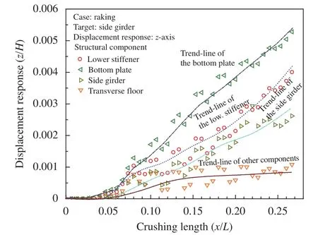
Fig. 12.Displacement of the components in vertical direction.

Fig. 13.Response contours of the double bottom after impacted to the side girder.
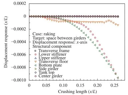
Fig. 14.Displacement on x-axis after contact on the space between girders (bottom tank).
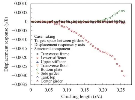
Fig. 15.Transversal displacement of the structural components against impact on the tank.
The strain contours in Fig. 17 show distribution of failure strain on the contacted elements with the indenter. In the initial contact, transverse floor and bottom plate were the highly crushed component while the stiffener was indented on the tip part. As deeper penetration on the structure, clean opening was formed which the bottom plate and stiffener got pushed back with characteristic as presented in displacement responses.Contour on the effective stress (Fig. 18) also illustrated that hot spot formed triangle contour in the initial structure-rock interaction. In this location, stress was found distributed to other components through three stiffener (t = 0.2 s).
Large opening was formed on the first compartment during t= 0.3 s, and it was followed by floor breaching in the end of the penetration. It can be stated that raking phenomenon on the bottom tank tends to produce more local damage on one or two compartments. It is very different with the tendency of impact to girder which may cause damage on two until four tanks consec-utively due to failure on girder-floor intersection. However, the girder is providing more resistance as smaller opening occurred in the end of impact to the girders. It may slow the spillage time of oil or waste which is kept on the bottom tank.
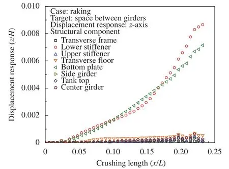
Fig. 16.Component displacement on the vertical direction during tank-rock interaction.
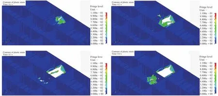
Fig. 17.Strain contours of the double bottom in impact on the tank.
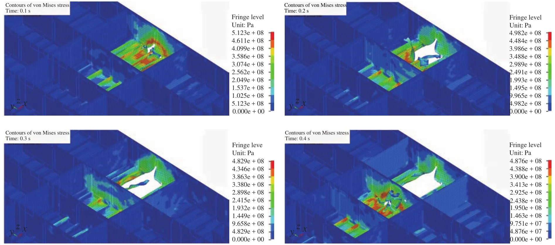
Fig. 18.Von-Mises stress contours surrounding the tank under raking.
6Conclusions
This work was addressed to observe structural responses of the double bottom components against a variety of accidental phenomenon, namely powered-hard grounding or raking. Based on results of several designated targets on the double bottom,quantification of the displacement response for the components was satisfyingly conducted. Against a conical topology, girders showed flapping tendency to transverse direction during penetration by the indenter, while on contact to the bottom tank(space between girders), displacement of the stiffener and bottom plate dominated other structural components. It was also concluded that comparing the displacement response ratio for all directions, main components mostly displaced on vertical direction. A prediction related to the displacement behaviour can be stated that if indenter height which contacts to a structure during raking is equal or higher than double bottom height,and conical angle is very close to 90°, the ratio value of displacement response on longitudinal direction (x-axis) will increase.This statement is proposed according to behaviour of structural component that will be pushed back during penetration by the indenter. In terms of response contours, percentage of thickness reduction indicated that massive reduction occurred on the elements near damaged components. This phenomenon is match with characteristic of necking on material which experiences excessive loads, or in this case is impact with conical rock. On the other hand, distribution of plastic strain was found to be following characteristic of structural geometry and penetration direction, e.g. during contact with transverse floor, strain was expanding to vertical and transverse directions. The strain and thickness reduction are two components which only affect contacted part during interaction of two entities, or it can be stated that the effect is more localized. However, the stress expanded its influence on structure widely to other component, even though the components have not directly interacted with other entity. It is also noted that expansion of stress contours will be more explicit on the transverse direction when the indenter reached deeper penetration on the structure.
Main results obtained from this work showed that displacement behaviour of local members subjected to impact loading will be very dynamics. Member performances of double side structure, besides inner shell, under impact will be also expected to experienced similar tendency as the grounding but different pattern will occur. Therefore, assessment on side structures regarding member behaviours are highly recommended, especially accounting for collision and explosion. Specific damage investigation can be directed to assess length of progressive contours on the impacted target in order to quantify expansion level during impact phenomenon occurs on certain structures.
杂志排行
Theoretical & Applied Mechanics Letters的其它文章
- Lattice Boltzmann model of percutaneous drug absorption
- Seepage-stress coupled modeling for rainfall induced loess landslide
- Dependency of gamma oscillations in E/I neuronal network on illumination contrast of external stimulus
- An energy approach to predict electromigration induced grain rotation under high current density
- Optimal control of a mobile robot on sphere
- Key structure in laminar-turbulent transition of boundary layer with streaky structures
