Contact Tracking Control Strategy for Space Manipulator with Snare-Type End-Effector
2019-03-07ZHANGLongCHENGang
ZHANG Long,CHEN Gang
1.Key Laboratory of Space Utilization,Technology and Engineering Center for Space Utilization,Chinese Academy of Sciences,Beijing 100094,P.R.China;
2.School of Automation,Beijing University of Posts and Telecommunications,Beijing 100876,P.R.China
Abstract:The capture operation performed by a snare-type end-effector mainly relies on three flexible cables.T his paper solves the dynamics modeling problems of flexible cable used in the snare-type end-effector and provides a contact tracking control strategy for the impact phase of snare capture.To describe the motion of flexible cable,a dynamics model is established by considering both tensile and bending resistance properties.On this basis,a virtual spring concept is introduced to represent the contact between flexible cables and the target grapple shaft,and a contact dynamics model is established approximately by polynomial function with the variables of penetration and start-end distance of flexible cable.Thereafter,a contact tracking control strategy is proposed to improve the reliability of space snare capture.The target grapple shaft and flexible cable can keep in contact at the initial contact point during the whole capture process and thus reduce the possibility of pushing the target away.Experiments are carried out to verify the effectiveness of the proposed method.
Key words:space manipulator;snare capture;dynamics model;control strategy
0 Introduction
With the continuous development of space exploration,space manipulator has played a key role in space tasks,especially for the capture operations,like payload deployment,orbital replaceable units manipulation,on-orbit construction and assembly,and so on[1-2].More and more types of end-effectors are designed for space manipulators to meet the increasing requirements[3-5].In terms of capture characteristics,these end-effectors can be classified into three categories in general:rigid,flexible and rigid-flexible coupled.
Snare capture is a capture mode performed by a rigid-flexible coupled end-effector,which consists of snare,rigid,and latch subsystem.It inherits some merits from the rigid and flexible end-effectors,such as high stiffness connection,flexible contact and so on[6].However,its secure operation depends greatly on the skill of the operator.In microgravity environment,the capture operation becomes quite complicated,and will be subject to high risk if improper control strategy is implemented.This paper concentrates on the dynamics problems during space snare capture,and based on the analysis results,a useful control strategy is proposed.
With regard to the snare capture,most researchers pay attention to its dynamics modeling problems.Li et al.[7]simplified the capture process and regarded the snare capture mechanism as a retractable rigid ring without considering the physical property of flexible cable.Tan et al.[8]proposed a discrete model of flexible cable based on torsion spring and then established the force and torque static equilibrium equations to predict the motion state of flexible cable.Only bending resistance property could be reflected by this model.Rong et al.[9]adopted absolute nodal coordinate formulation to describe the motion of transverse isotropic flexible cable and introduced the nonlinear contact force to reveal the interaction between flexible cable and target grapple shaft.However,the assumption that the coefficients of the contact force formulation were constant was not reasonable.Abiko et al.[10]conducted a lot of ground experiments to collect the data of applied forces and the corresponding penetration of flexible cable,and based on this,the contact force formulation was approximated by empirical equations.The initial state of flexible cable was ignored in the study.Yoshinitsu et al.[11]utilized the above results to simulate the H-II transfer vehicle(HTV)capture mission with space station remote manipulator system.There are few literatures concerning the control problems during space snare capture.As is known,a whole capture process can be divided into three phases,namely target chasing control phase which is also called pre-impact phase,impact phase between the target and the end-effector,and stability control phase of tumbling motion which is also called post-impact phase[12-13].Tan et al.[14]and Pan[15]both aimed at the pre-impact phase,and proposed similar control strategies which mainly depended on slowing down the relative velocity between flexible cable and the target to reduce the contact force.Our previous work[16]proposed a twostep capture strategy for the pre-impact phase.A“safe contact region”was designed to reduce the peak value of contact force and an optimal factor was provided to reduce the disturbance of the end-effector caused by impact.Takahashi[17]designed an impedance control method for space manipulator to track the floating target during snare capture.However,he assumed that the flexible cable did not rotate during the capture process,which seemed not reasonable.
This paper solves the dynamics modeling problems of flexible cable used in the snare-type end-effector and provides a control strategy for the impact phase of snare capture.The dynamics model and contact dynamics model are established firstly to analyze the motion of flexible cable and calculate the contact force,respectively.On this basis,with the consideration of reducing the possibility of pushing the target away,a contact tracking control strategy is proposed to complete the snare capture.
1 Problem Description
Snare capture mechanism mainly relies on three flexible cables of snare subsystem to capture the target equipped with grapple shaft.The flexible cables each have one end secured to the stationary ring and the other end secured to the rotary ring.When the target grapple shaft gets into the enclosed area formed by three flexible cables,the rotary ring begins to rotate to make the enclosed area narrower and narrower until the target cannot move in space,and then the target is latched by latch subsystem.The specific capture process is described in Fig.1.

Fig.1 The process of snare capture
(1)The snare-type end-effector approaches the target grapple shaft to make it insert into the enclosed area formed by three flexible cables.
(2)The rotary ring rotates with respect to the stationary ring to narrow the enclosed area until the target is constrained geometrically owing to the flexible cables fully tightening.During the capture process,the target may contact several times with three flexible cables.
(3)The target grapple shaft is dragged into the cylinder of the end-effector by the flexible cables.And it will be latched by the latch subsystem when the end-effector and target fully contacts.
From the description above,it can be seen that flexible cable plays a key role in snare capture,and its dynamics models need to be established to solve the motion and contact problems.During space snare capture process,the target may contact several times with flexible cables,which makes this capture mode face a big risk of pushing the target away.Based on the dynamics models of flexible cable,this paper will provide a contact tracking control strategy to keep the flexible cable contact with the target until the capture operation is finished,and thus reduce the possibility of pushing the target away.
2 Mathematical Model of Flexible Cable
2.1 Dynamics model
The flexible cable is assumed to be a series of mass points which are labeled B1,B2,B3,…,BNin sequence from one end to the other,and adjacent mass points are connected by massless tension spring.A torsion spring is installed on every mass point to reflect the bending resistance property of flexible cable.To describe the motion of flexible cable,three kinds of coordinate frames are established as shown in Fig.2,including the inertial frame O-XYZ,the i th fixed frameand the i th rotating framewhich can be gotten by two successive rotations:the first rotation ofabout z-axis by angleϑand the next one about the current xˉ-axis by angleφ.
The transformation matrix from the i th fixed frame to the i th rotation frame can be obtained by

Fig.2 Discrete model of flexible cable

where R(z,ϑi)and R(xˉ,φi)are the basic rotation matrices representing rotations about z and xˉaxes byϑiandφi,respectively.
As Hiis continuously differentiable as a function of time,the angular velocity matrix of the i th rotating frame can be calculated by[18]

Taking advantage of its skew symmetric property,the angular velocity of the i th rotating frame with respect to the inertial frame can be obtained as

Defining lias the vector of the i th segment of flexible cable expressed in inertial frame,its velocity can be calculated by

where l˙iis the velocity amplitude along the i th segment of flexible cable andaxis unit vector of
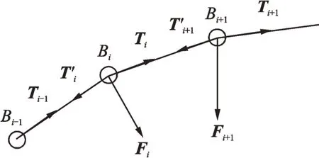
Combining Eq.(3)with Eq.(4)and expressing the final result with respect to the i th rotating frame,the following expression can be obtained.Considering the forces applied on nodes Bi,Bi+1as shown in Fig.3,the force equilibrium equation for the i th segment can be established by


where mi,mi+1are the masses of Bi,Bi+1,respectively.Fi=[Fix,Fiy,Fiz]T,Fi+1=[F(i+1)x,F(i+1)y,F(i+1)z]Tare the external forces applied on Bi,Bi+1,respectively.Ti,T'iand Ti+1,T'i+1are the tensile forces applied on Biand Bi+1,respectively.

Fig.3 Force analysis of nodes Bi and Bi+1
Combining Eq.(5)with Eq.(6),the dynamics equation of flexible cable can be obtained as

where xr=[ϑi,φi,li]T,with i=1,2,…,N-1,and if i=1,all variables with subscript label(i-1)turn to be zero,and if i=N-1,Ti+1,ϑi+1,φi+1turn to be zero.Hr,Cr,Prand Frare the inertial matrix,the nonlinear term,the potential energy term and the external force term,respectively.
The above derivation only considers the tensile property of flexible cable and for its bending resistance property,an equivalent structural force method[19]is introduced.The magnitude of bending moment produced at node i can be calculated by

where ktand ctrepresent the stiffness coefficient and damping coefficient of torsion spring,respectively;βi=φi-1-φiis the angle betweenits angular velocity;βi0the initial angle when no external forces exist.
The structural forces are required to balance the moment and at the same time must be self-equilibrated.In Fig.4,Fi,i-1,Fi,iand Fi,i+1are the equivalent structural forces acting on node i-1,i and i+1 in terms of bending moment Mi,respectively.And they satisfy the following conditions.

where i=1,2,…,N.If i=1,Fi,i-1=0,and if i=N,Fi,i+1=0.ei,i-1and ei,i+1are the directions of vectors Fi,i-1and Fi,i+1,respectively.

Fig.4 Equivalent structural forces
The bending moment has been transformed to the equivalent structural forces and these forces can all be regarded as the external forces acting on the nodes.In other word,Fi,i-1,Fi,iand Fi,i+1can be directly substituted into Eq.(6)as a part of Fi-1,Fiand Fi+1.So far,the dynamics model of flexible cable has been established considering both tensile and bending resistance properties.
2.2 Contact dynamics model
The contact between flexible cable and the target is a very complex process in microgravity environment.To simplify the modeling process,some reasonable assumptions are made in the following.
(1)The contact force only acts on the node,actually if the number of nodes is large enough,this could be realized.
(2)To improve the reliability of capture operation,the relative velocity between the target grapple shaft and flexible cable should be low enough.
(3)On account of the small deformation caused by contact,the contact force direction keeps the same during contact process.
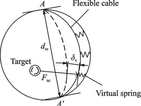
According to the reaction of flexible cable when suffering an external force,we could image that there is a virtual spring installed between the node and the ring,as shown in Fig.5.However,the contact force cannot be simply calculated by Hertz damping model,because the stiffness coefficient of virtual spring is not a constant.Actually,the stiffness coefficient is related to the start-end distance dseand the penetrationδv,which is determined by the displacement from initial contact position in normal contact direction.As a result,the contact force between flexible cable and the target grapple shaft is also related to dseandδv.The contact force model has been established by the following fitting function after lots of computational experiments has been done in our previous work[16].

where f(δv)and g(dse)are the polynomial functions ofδvand dse,respectively;h(δv,dse)represents the coupling function with variablesδvand dse.

Fig.5 Contact model of flexible cable
3 Contact Tracking Control Strategy
During snare capture process,the contact may happen several times and thus cause frequent disturbances to the end-effector of space manipulator.To improve the reliability,a contact tracking control strategy is proposed to keep the contact between target grapple shaft and flexible cable until the capture task is completed.Only one contact happens during the whole capture process by this method.
Fig.6 shows the capture process by contact tracking control strategy,it can be seen that the target keeps contact with the flexible cable until it’s totally enclosed.The key point of this control strategy is to keep the initial contact point tracking the target.The flexible cable and the end-effector both move during snare capture process and thus produce composite motion at the contact point.To avoid the contact with the other flexible cables due to the motion,the initial contact point needs to lie in the middle region,namely the“safe contact region”[16]and this can be realized through pre-impact control strategy.

Fig.6 T he contact tracking control strategy
3.1 Composite motion of contact point
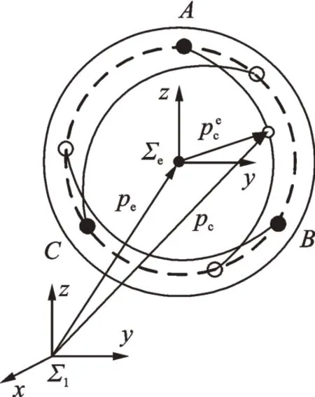
The dynamics model has been established in Section 2,and the position and velocity of each discrete node of flexible cable can be known as long as the motion of the rotary point is given.In Fig.7,represents the position of contact point with respect to the end-effector frame,Reis the transformation matrix from the end-effector frame to the inertia frame and peis the end point expressed in the inertia frame.During the snare capture,both Reand pecan be obtained through the kinematics model of space manipulator or other measuring equipment.peccan be obtained by the dynamics model of flexible cable.Therefore,the contact point position expressed in the inertia frame can be timely obtained by

Fig.7 T he position of contact point

3.2 Joint controller model
The equations governing the motion of a freefloating space manipulator as a multi-body system can in general expressed by[18]

where D is the inertial matrix,the end-effector acceleration,c the nonlinear velocity-dependent term,Feqthe equivalent driving force at the end-effector,and Fethe force acting on the environment by the end-effector.
The controller model can be designed as

where Mi,Biand Kiare all diagonal positive definite matrices,representing desired inertia,desired damping and desired stiffness,respectively.are the end-effector position and velocity of space manipulator.are the position,velocity and acceleration of the target contact point.Fdrepresents the desired contact force.The ideal value of Fdis zero which can make the end-effector just contact with the environment.However,to ensure the contact and do not damage the target or push the target away,the value of Fdwill often be small positive constant.
Substituting Eq.(13)into Eq.(12)yields

where e=xt-xe,Fd)could be regarded as the driving force to make the end-effector approach the target.When the contact force reaches the desired value,the snare-type end-effector does keep in contact with the target at the contact point.
According to the duality principle,the joint torque controller model is designed as

where JTfis the transpose of Jacobian matrix Jf.
The stability of the proposed controller model is analyzed as follows.For simplicity,it is considered that the contact force is applied to only one direction.And let mix,bix,kix,fd,feand e be the elements of Mi,Bi,Ki,Fd,Feand e,respectively.Then,Eq.(14)becomes

Substituting fe=-kee with kerepresenting the stiffness of the environment into Eq.(16)yields(In the practical experiment,Feis obtained by the force sensor)

Eq.(17)is a second order constant coefficient nonhomogeneous linear differential equation,and its solution can be solved as

whereλ1<0,λ2<0(λ1≠λ2)are the eigenvalues of the eigen equation corresponding to Eq.(17)by choosing proper gains mix,bix,kix.It can be known that if t→+∞,e(t)→which proves that the system is asymptotically stable.
4 Experimental Verification
4.1 Flexible cable model
The theoretical verification experiment is carried out on the air-floating platform,which consists of base,manipulator,target and the data measurement sensors as shown in Fig.8.

Fig.8 Experimental platform
In this paper,the dynamics model of flexible cable is established first,and on this basis,the contact model is established.Therefore,a verification scheme is designed based on the contact force measurement experiment to verify the accuracy of both the dynamics model and contact model.Since the contact between the target and the flexible cable mainly depends on its relative velocity,the equivalent idea is adopted,namely the capture rod installed at the end-effector,and the snare capture device installed at the target whose total mass is 41.7 kg and moment of inertia is diag[3.41,3.15,1.61]kg·m2.
The diameter of the snare capture ring is 0.35 m.The specific parameters of its equipped flexible cable are:diameter 3 mm,effective length 0.3 m,linear density 0.036 5 kg/m,initial total bending angle 26°,the start-end distance 0.26 m.The flexible cable is divided into 30 segments.And the experimental steps are as follows:
(1)Based on the proposed modeling method,the contact model at the contact point is established.For example,the contact model for point 16 can be expressed as

(2)For the same contact point,its relative contact velocity is changed and the corresponding contact force curve can be obtained.
(3)For the same relative contact velocity,its contact point is changed,and the corresponding contact force curve can be obtained.
(4)The accuracy of the proposed theoretical model can be calculated by

where Fa_maxand Ft_maxare the contact force peaks obtained by fitting the actual sampling data and the theoretical simulation,respectively.
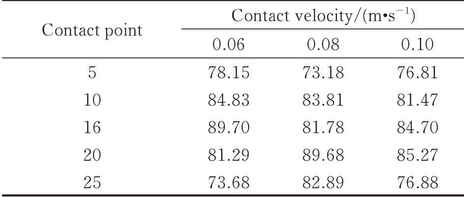
The analysis results are listed in Table 1,and the average model accuracy is 81.61%.It can be found that when the contact happens in the middle region of the flexible cable,the model accuracy is relative high.The errors may come from the following aspects:
(1)The data collected by the force sensor is interfered by the external noise;
(2)There are frictional forces,installation errors,measurement errors,fitting errors and so on;
(3)There exists a gap between the flexible cable and the positioning bolt because of insufficient locking force.

Table 1 Model accur acy of flexible cable %
4.2 Contact tracking control str ategy verification
A 4-degree-of-freedom manipulator is studied as shown in Fig.8,with its kinematics and dynamics parameters listed in Tables 2 and 3.The reference coordinate systems are established at each joint with z pointing the direction of joint rotation and x along the link.

Table 2 Kinematics parameters

Table 3 Dynamics parameters
The initial angles are[-0.44,0.84,0.38,0]rad.As the manipulator lies in the xy plane,the joint controller parameters are set as Mi=diag(2,2),Bi=diag(15,15),Ki=diag(1,1).The desired contact force amplitude is 2 N.
Fig.9 shows the contact tracking control process.Due to the size of the air-floating platform,the control process is implemented within 5 s.Fig.10 shows the contact force collected by the force sensor during the capture process.It can be seen that the denoising data keeps around the desired force after about 0.50 s,which means that the end-effector keeps contact with the flexible cable.And the average contact force between the effective interval 0.5—5 s is 1.87 N.The average error between actual contact force and the desired force is 6.5%.

Fig.9 The contact tracking control process

Fig.10 The tracking error of contact force
5 Conclusions
Snare capture is a capture mode mainly depending on three flexible cables to enclose and latch the target.Due to its advantages of large tolerance and flexible contact for capture operations,this capture mode becomes more and more popular.However,the dynamics and control problems of flexible cables used in the snare-type end-effector are still quite complex.The main contribution of this paper is that a contact tracking control strategy to improve the capture reliability is proposed with the consideration of the composite motion of the flexible cable.This work would have potential applications in predicting the snare capture process and help to find out the potential risks to avoid an accident in capture operation.Although many factors have been already considered,the established model is still a simplified one compared to the real situation.In the following study,we will focus on the improvement of the models.Meanwhile,the improvement of ground experiment conditions will also be the main work.
杂志排行
Transactions of Nanjing University of Aeronautics and Astronautics的其它文章
- GA-iForest:An Efficient Isolated Forest Framework Based on Genetic Algorithm for Numerical Data Outlier Detection
- Computationally Efficient Direction of Arrival Estimation for Improved Nested Linear Array
- Numerical Simulation on Intergranular Microcracks in Interconnect Lines Due to Surface Diffusion Induced by Stress-,Electro-and Thermo-migration
- Modeling and Characteristic Analysis of Visco-Hyperelastic Film Based on Biaxial Tensile Experiment
- Experiment on Vaporization of Jet into Cross-Flow
- Nonlinear Modeling and Identification of Structural Joint by Response Control Vibration Test
