Experiment on Vaporization of Jet into Cross-Flow
2019-03-07MACunxiangDENGYuanhaoYANYingwenXUHuasheng
MA Cunxiang,DENG Yuanhao,YAN Yingw en,XU Huasheng
1.AECC Sichuan Gas Turbine Establishment,Chengdu 610500,P.R.China;
2.College of Energy and Power Engineering,Nanjing University of Aeronautics and Astronautics,Nanjing 210016,P.R.China
Abstract: The injection characteristics of the main fuel nozzle,which is widely applied in advanced lean-premixed-prevaporized(LPP)low-emission combustors,can be simplified as the atomization and vaporization processes of a jet into cross-flow.In this study,a nozzle with a diameter of 0.4 mm is designed and processed through the heating of the inlet air,and the vaporization characteristics are investigated.The optical measurement and cyclone separation methods are separately used to investigate the evaporation rate of a jet into cross-flow.Experimental results show that the fuel evaporation rate in cross-flow is mainly affected by the Weber number(We),equivalent ratio(φ),momentum rate of fuel to air(q),and air temperature.In addition,the inlet temperature is a crucial factor for the evaporation ratio of a jet into cross-flow.The evaporation results measured by two different methods in the same cross-flow are very close to each other with a deviation within 10%.
Key words:evaporation rate;jet;cross-flow;optical measurement;cyclone separation method
0 Introduction
It is important for aero-engines to have high propulsion efficiency,high total pressure ratio,and high turbine inlet temperature.However,it is also important for civil aviation engines to be inexpensive,eco-friendly,quiet,and highly reliable to be competitive in the market.With the rapid development of the air transport market,aero-engine pollution emission is sharply increasing.Pollutants such as NO x(NO,NO2,etc.)and CO2are exacerbating the greenhouse effect of the atmosphere and deteriorating the global climate,causing the aero-engine pollution emission standards to become increasingly stringent.Therefore,the low-emission combustion technology is one of the key technologies for the future development of civil aviation engines[1].
At present,lean low-emission combustion technology and rich low-emission combustion technology have been developed to help lower aero-engine emissions.The twin annular premixed swirler(TAPS)combustion chamber of general electric(GE),and the lean burn combustion chamber of rolls-royce(RR) are representatives of lean low-emission combustion technology,while the technology for advanced low NO x(TALON X)combustion chamber is a representative of rich low-emission combustion technology[2].All of these have achieved great successes in reducing NO x emissions,particularly the TAPS combustion chamber,which represents the most advanced lean low-emission combustion technology and uses the direct injector of multiple jets in main fuel atomization.The fragmentation,evaporation of the fuel and the fuel-air mixing uniformity in cross-flow strongly influence the emission performance,combustion performance,and so on,[3-8]making it a very important research direction for lean-premixed-prevaporized(LPP)low-emission combustion technology.The energy transfer between a liquid hollow cone spray and the surrounding air was investigated using both imaging and phase-Doppler techniques[9].Results indicate that the formation of the hollow cone spray and the interaction of the fragments and droplets with the air,through viscous drag,induce complex entrained airflows.In addition,Xie et al.[10]also studied the spray characteristics and heat transfer performance of pressure swirl nozzles in an open loop system.Ref.[11]introduced a method of calculating the steady evaporation rate of a single droplet.The reliability of the method was verified by the comparison with the experimental data.Ref.[12]introduced the study of single-component fuel(such as heptane)instead of the kerosene droplet evaporation constant along with the change of pressure and temperature.Through calculation and experimental comparison and analysis,it was found that the droplet evaporation rate can be calculated more accurately theoretically.Ref.[13]studied the evaporation distances of droplets with different diameters(25 μm,50μm,75μm,and 100μm)at different temperatures(500~1 000 K)under normal pressure by using a one-dimensional calculation equation with smaller particle sizes and faster evaporation,and compared the results with those of the three-dimensional calculation.It was found that the degree of evaporation from the one-dimensional calculation was higher.
Domestic and foreign studies focus more on the cross-flow injection atomization characteristics than on the cross-flow injection evaporation ones,as they are generally more concerned with the calculation of the evaporation rate of a single droplet than that of the evaporation rate of the droplet group.In this study,the characteristics of the cross-flow injection atomization and evaporation are investigated under the atmospheric pressure and temperature(45℃,75℃and 115℃)conditions.These results will guide the design of the fuel atomization of the premixed section in LPP combustor.
1 Experiment Subject
A simple direct nozzle is used in the study,whose sketch map and material object are shown in Figs.1 and 2.Here do is the nozzle diameter(0.4 mm),l the nozzle length,and the nozzle is welded to the base fuel pipe joint to set the nozzle length to the diameter ratio l/do be 4.

Fig.1 Sketch map of direct nozzle

Fig.2 Direct nozzle for experiment
2 Experimental Procedure
2.1 Experiment system
As shown in Fig.3,the experiment system is mainly composed of a gas tank,an air compressor,an electric heater,a storage tank,the test section,the relevant control system,and the emission system.The air flow is measured by an orifice flowmeter,and the total temperature of the inlet air is measured by a standard k-type nickel chrome-nickel silicon armored thermocouple.The total pressure measuring point of the inlet air is composed of a total pressure probe and pressure sensor.The high-speed camera and LED light source used in the experiment are shown in Fig.4.The high-speed camera has 2 336 pixels×1 728 pixels.The maximum shot is 1 455 frames per second.Fig.5 depicts the optical measurement system for studying the evaporation rate of the cross-flow injection.Fig.6 shows the measurement system of the fuel evaporation rate in the cyclone separator.To avoid further evaporation of non-evaporated fuel in the cyclone separator cylinder,cooling water is sprayed to cool down the temperature of cyclone separator cylinder,and an armoured thermocouple is used to detect the wall temperature of the cylinder.By adjusting the flow rate of cooling water,the temperature of the cylinder is slightly lower than the evaporation temperature of aviation kerosene-Daqing RP3. That is,the non-evaporated fuel would not evaporate further.Evaporated fuel vapor will not condense into liquid fuel.The experimental study shows that the diameters range of fuel droplet size distribution is about 30 μm to 80μm under different working conditions.Therefore,the minimum effective particle diameter of the designed cyclone separator is 5μm,and the relevant structure size of separator is selected by synthesizing the size of test sample and test conditions[14-15].Calculations verify that the separation efficiency is about 98%for the minimum particle diameter selected in this experiment.

Fig.3 Sketch map of test system

Fig.4 Optical testing instrument

Fig.5 Optical test system of fuel evaporation
2.2 Exper imental method
In this study,optical and physical measurement methods are separately used to study the fuel evaporation rate of the nozzle,so the evaporation rate is obtained,and mutual verification is carried out.
2.2.1 Optical measurement method

Fig.6 Cyclone separator test system for fuel evaporation
There is a side window and a back window on the test piece.The back window is installed on a buffer cavity,which can stagnate the high-speed fuel spray and help it avoid a collision with the back window,as shown in Fig.5.The planar laser emitted from the laser through the side window illuminates a downstream cross-section of the nozzle(The cross-section can be within a range of 0—50 mm from the nozzle).The high-speed camera captures the light scattered by the fuel droplet from the illuminated interface,which is perpendicular to the direction of airflow,and obtains the original image of the cross-section fuel spray field.
After the images are captured by the camera,they are processed by image post-processing technology and then analyzed by the spray field processing software to extract the desired information,such as the fuel droplet diameter and the spatial distribution on the cross-section.Then,the mass of all the unevaporated droplets on the cross-section is calculated.The diameter and quantity of fuel particles in gray images are extracted by the edge detection method,which is based on the discontinuity of image information.At present,the commonly used edge detection algorithms include the Sobel and the Roberts methods.The Roberts detection algorithm uses the difference between two adjacent pixels in the diagonal direction to calculate the intensity of the pixel boundary.The detection effect of oil droplet edge is better than the Sobel method,so this experiment uses the Roberts algorithm to extract oil droplet information.The image post-processing technology has been verified by a large number of experiments,and the specific process is described in Ref.[16].By changing the inlet parameters of air and fuel,the evaporation rate of the fuel on the cross-section is studied at different parameters.
2.2.2 Physical measurement of cyclone separator method
The fuel atomizes and evaporates in the test section after being ejected from the nozzle,as shown in Fig.6.This exit channel of the test section,which is at a given distance from the nozzle outlet,is tangential to the designed cyclone separator cylinder body.The fuel mixes with the air,and this mixture tangentially flows into the fuel cylinder.Under the centrifugal force,the droplets with larger masses are separated from the mixture of fuel and gas and flow along the wall into the fuel catcher bottom.The vaporized mixture which may contain droplets with small diameters is discharged through the exhaust pipe from the central pipe of the clone separator.During the experiment,the separator cylinder wall is drenched in cooling water.And simultaneously,the thermocouple laying on the cylinder wall surface monitors the cylinder temperature,which can weaken the evaporation of the unevaporated fuel in the cyclone cylinder and avoid the condensation of the fuel vapor into liquid fuel to the most extent.
2.3 Experimental status
To study the evaporation characteristics of cross-flow injection,the optical measurement and swirling separation methods are separately used to measure the evaporation rate of fuel.The working conditions of the cyclone separation measurement are shown in Table 1 Partial conditions(condition 9 to 11,and 14 to 16)are verified with the optical measurement method.The evaporation rates of fuel at three inlet temperatures are studied according to the capacity of the heating equipment.
3 Results and Analysis
3.1 Optical measurement results
For the simulated nozzle,the effects of Weber number We and liquid-gas momentum ratio q on the fuel evaporation rate are studied by the optical method at the downstream cross-sections of 20 mm and 25 mm.The flow area of the nozzle can be calculated according to the internal diameter of the nozzle.Then the fuel velocity magnitude is calculated based on the specific fuel flow.
Table 2 shows the fuel evaporation rate on the 20 mm-cross-section at three different statuses(9,10,and 14 working conditions).It can be seen from the table that under the same We,the fuel evaporation rate decreases with the increase of the momentum ratio q;i.e.,the quality of atomization decreases as the fuel increases,and under the same q,We increases as the aerodynamic force increases.This improves the fuel atomization,and the fuel evaporation rate correspondingly increases.The evaporation rate is defined as,whererepresents the total fuel flow rate,and M˙residue fuel flow rate calculated from optical method or physical method.The momentum ratio is defined as q=whereρaandρfrepresent the density of air and fuel,respectively;U2aand U2frepresentthe velocity of air and fuel,respectively.

Table 1 Evapor ation test conditions by using the cyclone separ ator

Table 2 Rate of evaporation under different conditions
Fig.7 shows the average particle size distribution of the fuel spray field at the downstream cross-sections of 20 mm and 25 mm under the same inlet aerodynamic parameters(We≈140 and q≈24).The figure shows that,along the axial direction of the nozzle,the fuel droplet number greatly reduceds on the cross-section,while only a few of the larger diameter droplets,which are located on the core area of the cross-flow injection spray field,are captured.The droplets in the surrounding area have almost completely evaporated.
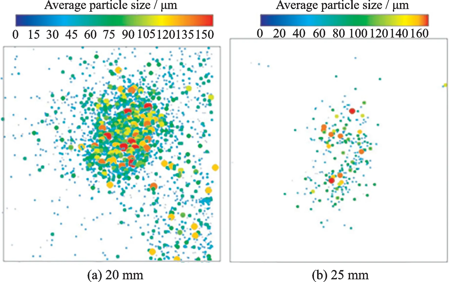
Fig.7 Comparison of oil mist field of jet cross-section under the same condition at different cross-sections
Fig.8 shows the N distribution curve of the average particle diameter at two cross-sections.It shows that along the axial direction of the nozzle,the number of fuel droplets in different cross-sections decreases rapidly,indicating that fuel droplets on the cross-section also evaporate rapidly with an increase in the distance.The diameter of the droplets on the cross-section decreases rapidly and the change in the number of larger droplets is very small.

Fig.8 Average particle sizes with N at different cross-sections
Table 3 shows that under the same inlet aerodynamic parameters,the fuel evaporation rate in the cross-section increases from 55%to 72%when the axial distance to the nozzle increases from 20 mm to 25 mm,which shows that the position of the cross-section greatly influences the fuel evaporation rate.Therefore,the distance between the main nozzle of the LPP combustion chamber and the outlet of the swirler should be selected and optimized according to different evaporation rates.

Table 3 Rate of evaporation at differ ent distances from the nozzle
3.2 Physical measur ement results of cyclone separator
Table 4 shows the test results of the evaporation rate for the cyclone separation method(20 mm from the nozzle outlet).As is shown in the table,when the inlet air temperature and flow rate are constant,the evaporation rate decreases as the fuel flow rate increases.However,when the inlet air flow rate is small and the temperature is low,the fuel evaporation rate increases with the fuel flow rate.This is most likely because a small inlet air flow rate negatively impacts fuel evaporation,causing more fuel droplets.As a result,a large number of fuel droplets flow into the cyclone separator with the air flow.And because the small initial rotation momentum negatively impacts the effective separation,some drops end up being carried away by the air flow.Therefore,the evaporated portion of the fuel increases with the total fuel flow rate,and the calculated value of evaporation efficiency also increases correspondingly.Hence,this method is erroneous under the condition of low inlet temperature and small airflow speed.So under the circumstance of low inlet velocity and low inlet temperature,the optical method for calculating the fuel evaporation is superior and recommended.
Under the air inlet condition of high speed and high temperature,the cyclone separator can separate the gas and liquid mixtures more effectively,and the evaporation efficiency values can be measured in accordance with the physical law,which states that the fuel evaporation efficiency decreases as the fuel flow rate increases.This is most likely because when the fuel flow rate increases,the fuel droplets require more heat to evaporate.Therefore,at the same inlet temperature,the fuel evaporates slower as the fuel flow rate increases,causing a corresponding decrease in the evaporation efficiency.The evaporation efficiency increases sharply when the inlet temperature increases for the same fuel flow rate(Fig.9).This is because the evaporation of the liquid phase depends primarily on the temperature.

Fig.9 The rate of evaporation at different air temperatures

Table 4 The r ate of evapor ation with cyclone separ ator
3.3 Comparative analysis of the two measurement r esults
Evaporation rates between the cyclone separation and optical measurement methods are obtained(Table 5).The fuel evaporation rates measured on the cross-section 20 mm from the nozzle by the two methods are different under six different aerodynamic parameters,and the difference is less than 11%.When the inlet We is large(working conditions 14,15,and 16),the deviation in fuel evaporation rates measured by both methods is small.On the contrary,when We is small,the deviation is large,and both measured values are small.
During the cyclone separation fuel evaporation rate measurement process,a thermocouple is used to monitor the cylinder wall temperature to prevent the condensation of the evaporated fuel and further evaporation of the unevaporated fuel in the separation cylinder and to improve the test accuracy.In addition,the small fuel droplets,which are dischargedwith the air flow by the strong centrifugal force,are regarded as vaporized fuel vapors.
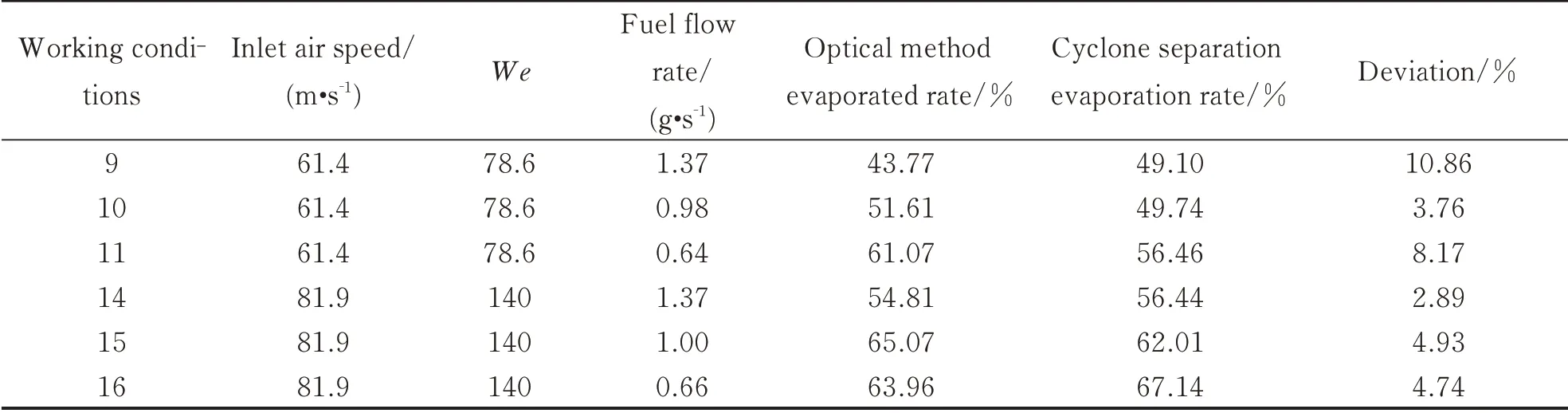
Table 5 Comparison of evaporation rate with optical method and cyclone separator
From the engineering perspective,the measurement values of the evaporation rate obtained by optical and physical separation methods under the same aerodynamic conditions agree well with most of the data.Therefore,it can be said that the optical measurement and cyclone separation method have the function of mutual verification,which further improves the reliability and accuracy of the evaporation rate measurement results.Fig.10 shows the comparison of the variation trend of the evaporation rate obtained by the two measurement methods with equivalent ratio.It can be seen from Fig.10 that at the same temperature,an increase in the equivalent ratio results in an increase in the richness of the fuel-air mixture.The fuel needs more heat to evaporate,which reduces the fuel evaporation rate.

Fig.10 Comparison of the evaporation rate withφ
4 Conclusions
This study takes the fuel injection of LPP combustor as the research prototype and simplifies it into a jet injection model to investigate the fuel evaporation rate.The test shows that:
(1)When other inlet parameters are consistent,the fuel evaporation rate on the cross-section decreases as the q and equivalent ratioφincreases;
(2)Experimental results of optical method for measuring diameters of the fuel droplets indicate that larger Weber number leads to smaller diameters of droplets.So We is the leading factor of liquid spray evaporation in the cross-section of the cross-flow;
(3)The fuel evaporation rate sharply increases as the downstream axial distance from the nozzle increases;
(4)In general,the temperature of the inlet air flow is a direct factor affecting the evaporation rate.Both methods verified that the fuel evaporation rate is about 60%when the inlet temperature and We are approximately 75℃and 140,respectively.
杂志排行

Transactions of Nanjing University of Aeronautics and Astronautics的其它文章
- BeiDou B1I/B3I Signals Joint Tracking Algorithm Based on Kalman Filter
- Impact Analysis of Solar Irradiance Change on Precision Orbit Determination of Navigation Satellites
- Characterization of Self-driven Cascode-Configuration Synchronous Rectifiers
- Cooperative Search of UAV Swarm Based on Ant Colony Optimization with Artificial Potential Field
- H∞Preview Control for Automatic Carrier Landing
- Single-Phase to Three-Phase Inverter with Small DC-Link Capacitor for Motor Drive System