Performance limitations in trajectory tracking control for air-breathing hypersonic vehicles
2019-01-16BoyiCHENYninLIUHidongSHENHoLEIYupingLU
Boyi CHEN,Ynin LIU,*,Hidong SHEN,Ho LEI,Yuping LU
aCollege of Astronautics,Nanjing University of Aeronautics and Astronautics,Nanjing 210016,China
bCollege of Automation Engineering,Nanjing University of Aeronautics and Astronautics,Nanjing 210016,China
KEYWORDS Bandwidth constraints;Hypersonic vehicles;Performance limitations;Robust performance;Trajectory tracking control
Abstract An integrated approach that considers the performance limitations of tracking control systems for air-breathing hypersonic vehicles is proposed.First,a set of ascent trajectories is obtained as candidates for tracking control through a trajectory design method that considers the available acceleration.Second,the basic theory of performance limitations,which is adopted to calculate the limits on control performance through the trajectory,is integrated.The openloop dynamics of air-breathing hypersonic vehicles is responsible for these limits on the control system.Comprehensive specifications on stability,tracking accuracy,and robustness are derived,and the flight envelope with constraints and control specifications is identified.Simulation results suggest that trajectory design should consider restrictions on control performance to obtain reliable solutions.
1.Introduction
Technological advances in the last decade have promoted research on Air-breathing HyperSonic Vehicles(AHSVs).1AHSVs are characterized by unstable longitudinal dynamics,non-minimum phase behavior of the flight path angle dynamics,strong loop interactions,and nonlinearity with uncertainty.2,3The dynamics of actuators and sensors also affect the performance of control systems.4The open-loop characteristics determined by plant and flight conditions result in limits on control performance that are independent of the control system design.5-7
The flight envelope of AHSVs is subject to path constraints8,including available lifting area,structural loads,and thermal flux.9The operating conditions of scramjets,such as thermal choking,ram-to-scram transition,and saturation of the Fuel Equivalent Ratio (FER)also define the flight envelope.10,11Therefore,trajectory design is formulated as a constrained optimization problem.However,the constraints mentioned above are insufficient to obtain a feasible trajectory due to the disregard of control performance.With uncertain non-ideal plant dynamics12,external environmental disturbances12,and restrictions on actuators13,14,a flight control system may fail to implement trajectory tracking appropriately.
Trajectory tracking for AHSVs encounters challenges originating from unstable dynamics with a saturated input,nonminimum phase behavior of flight path dynamics,and model uncertainties.15Hence,stability,tracking accuracy,and robustness of the control system are important to tracking control.However,numerous studies have revealed limitations in control performance.These limits are imposed by the nonminimum phase dynamics of the plant and input saturation.16Bolender and Doman17indicated that FER can be used to address limitations on the Flight Path Angle(FPA)bandwidth and suggested that a canard is required to achieve a high-speed response of FPA control.Rodriguez et al.explored the fundamental performance limitation for a class of AHSVs18and proposed a decentralized system-controller-reference design methodology.19Many anti-windup controllers have been designed to account for input saturation.20However,the majority of these methods require the plant to be stable.
The main issues in control system design are the instability caused by an unstable plant with input saturation and the FPA bandwidth limit imposed by the presence of non-minimum phase zeros.Limitations on control performance are mainly imposed by open-loop dynamics,which is related to the trajectory.Control specifications that exceed limits cannot be achieved regardless of the control system design.Therefore,limits on performance should be identified before designing the control system.
The motivation of the current control-relevant performance limitation analysis is the mismatch between the desired flight trajectory and the authority of the tracking control system.This mismatch is likely to be encountered in hypersonic vehicles.Therefore,the objective of this study is to integrate the performance of the flight control system with trajectory design.This integrated approach for hypersonic vehicles provides primary insights into the control-relevant performance of trajectory tracking and facilitates the design of reliable flight plans.
The remainder of this paper is structured as follows.Section 2 introduces a trajectory design method that considers acceleration constraints.Section 3 describes the performance limits of the control system imposed by open-loop dynamics.The main issues addressed in this section are stability,tracking accuracy,and robustness.Numerical illustrations of the control-relevant trajectory analysis are presented in Section 4.Section 5 provides the primary results of this work.
2.Constrained ascent trajectory design
This work focuses on the acceleration phase of AHSVs.A trajectory design method in the velocity domain is employed to solve the optimal acceleration trajectory.The merit of this approach is that it converts the problem of trajectory design into a path design problem and integrates the constraints on flight conditions into the constraint on acceleration.However,the application of the proposed method is restricted to the acceleration or deceleration phase,where a≠0.Hence,optimization of near-cruising flight and constant speed climbing is beyond the method’s capability.
The equations of motion of hypersonic vehicles over a rotating spherical Earth are given by

where V is the velocity,α the angle of attack,h the altitude,θ the pitching angle of the vehicle,q the pitching rate,γ= θ-α the flight path angle,m the total mass,and Iyythe moment of inertia about the y axis.L,D,T,M represent lift,drag,thrust,and moment,respectively.Also,g denotes the local gravity acceleration,and REthe mean radius of Earth.
The first step in this process is to define an altitude profile as a function of velocity h=h(V).A trajectory with the specific path h(V)is subjected to the acceleration profile a=a(V).Differentiating h(V)with respect to time leads to the analytical expression of FPA regarding the acceleration profile:

Taking another derivative of time,the derivative of FPA is obtained with respect to time:

The formulation has a singularity subject to the steep climb,where cosγ≈ 0.Herein,all trajectory states have been defined for a specific path h(V)with assigned acceleration profile a(V).The most concerned flight path is the ascent trajectory with the constant dynamic pressure.
Maintaining the constant dynamic pressure during flight is an important example of altitude profiles.Hence,the dynamic pressure may be regarded as a parameter of designed trajectories.The derivative of the altitude with respect to the velocity for the ascent trajectory at the constant dynamic pressure is formulated as:

where ρ(h)is the density of air concerning the altitude.
The trajectory in the velocity-altitude plane may be defined beforehand,and then the acceleration profile is optimized to obtain the optimal trajectory.The following subsection will provide the optimal conditions of the acceleration.
2.1.Optimal conditions of acceleration
The objective in the trajectory design is to minimize the fuel mass consumption during the ascent phase.Accordingly,the acceleration is selected as the control variable to optimize the trajectory.The fuel mass consumed during the ascent phase is calculated by:

where Vsand Vfdenote the magnitude of velocity at the start and end of ascent phase,˙mfrepresents the fuel mass rate.The design in the optimal ascent trajectory can be discretized by splitting it into a sequence of segments.Each segment features a pair of flight states(Vi,ai)and(Vi+1,ai+1),wherei=1,2,...,n+1 andnis number of segments.
Theoretically,a quadrature rule is an approximation of a function,and stated as a weighted sum of function values at specified points within the domain of integration.An-point Gaussian quadrature rule yields an exact result for polynomials of degree 2n-1 or less by a suitable choice of the points and weights.Using Gauss-Legendre quadrature method,21the total fuel consumption in Eq.(5)can be discretized as

whereVi(i=2,3,...,n)are the Gauss-Legendre nodes located in(Vs,Vf),andwiis the Gauss-Legendre weight of each node.The optimal condition regarding the accelerating trajectory has been deduced using the calculus of variations22:

The condition allows us to solve the optimal acceleration for each point individually.However,there exists no solution in view of the constraints on the acceleration.In this case,the maximum attainable acceleration is the optimal condition when the condition in Eq.(7)cannot be satisfied.22
2.2.Constraints on acceleration
The acceleration of air-breathing hypersonic vehicles mainly depends on the thrust provided by the scramjet.However,the thrust is limited by the operating condition of a dualmode scramjet propulsion system.The performance of the scramjet is determined by FER,the angle of attack,speed,and altitude.
The trajectory is assumed to be quasi-equivalent,which means the pitch rateqis zero at each point.Thus,the time derivative of the angle of attack is equal to the time derivative of FPA calculated using Eq.(3).As the optimal condition of Eq.(7)holds,the optimal acceleration can be solved by

The functiong(αi, φi, δe,i)is the constraints on the flight conditions,which include the operating condition of the scramjet,the saturation of FER,and the saturation of the control input.The optimal acceleration is simplified as the maximum attainable value in the case of no feasible solution from Eq.(8).The constrained optimization is formulated to solve the problem as follows:

Accordingly,the constraints on flight conditions are integrated into the constraint on the acceleration at each node on the pathh(V),thereby reducing the complexity of the optimization problem.The optimal acceleration profilea(V)is obtained for a specific flight path characterized by altitude profileh(V)as well as the flight states.Moreover,the open-loop characteristics of the AHSV throughout trajectories can be extracted.
Fig.1 illustrates the examples of the ascent path at constant dynamic pressures with the typical constraints on the flight envelope.However,these constraints are insufficient to obtain a reliable solution due to the disregard of the authority of the control system.Performance limitations on the control system reveal the connection between plant dynamics and closed-loop performance introduced in the following section.
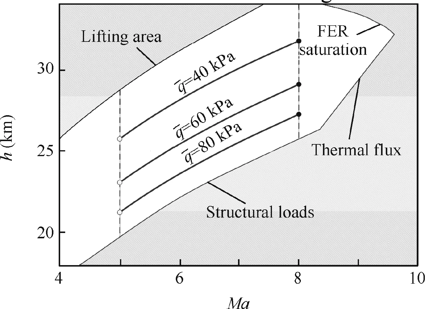
Fig.1 Ascent paths with respect to constant dynamic pressures.
3.Performance limitations of the control system
Trajectory tracking control for AHSVs encounters challenges originating from unstable dynamics with saturated input,non-minimum phase behavior of the flight path dynamics,model uncertainties,and wide flight envelope with extreme disturbances.Hence,the main issues addressed in this study are stability,tracking accuracy,and robustness of the control system.The null controllable region defines the domain of attraction,which is a measure of the stability of AHSVs.Instability in an unstable plant with a saturated input is a critical problem in control system design.Tracking accuracy is evaluated by the norms of the tracking error.This issue arises from the nonminimum phase behavior in the flight path dynamics.Peaks of sensitivity and complementary sensitivity functions are used to quantify the robustness of the control system,and model uncertainties and extreme disturbances are considered.
The limitations on these performance indicators are identified individually and synthesized.In conclusion,robustness is in conflict with tracking accuracy and maneuverability,and a comprehensive consideration of this performance should be adopted.These trade-offs and limits depend on the open loop dynamics of AHSVs,indicating that the tracking performance of the control system is related to the designed trajectory.
3.1.Null controllable region
The size of the null controllable region is a quantitative measure of stability,and such limitation is imposed by an unstable plant dynamic with input saturation.23Assume that a control inputu(t)is restricted by the actuator constraint ranging from¯u-to¯u+:u¯-≤u(t)≤u¯+∀t∈ [0,∞)
Besides,the actuator dynamic is restricted by a bandwidth ωa.Any control input that satisfies these conditions is called an admissible input,and the set of which is denoted asUa.
A state x0is said to be null controllable if there exists a finite timets,and an admissible control inputu∈Ua,such that the state trajectory x(t)satisfies x(0)=x0,x(ts)=0.The set of all null controllable states is called the null controllable region of the system,denoted asC.24Let the pair(A,b)of the LTI system be completely controllable,where b is the control matix in state equation of LTI system,and assume that A has a real unstable polepwith left eigenvector η,without loss of generality,ηTb>0.The closureC¯ and boundary∂CofCare given by

wherekC= ηTb/p.The left eigenvector η indicates the divergent direction of the unstable system states.With an admissible inputu(t)∈Ua,Cis defined bykC,which is just related to the open-loop dynamics.
The range of admissible disturbances of a statex,denoted as Δx,is bounded by

where exdenotes the unit vector in the direction of the statex,such as angle of attack α.Therefore,the value ofkCimplies the performance limit on stability.Also,the bandwidth of actuators ωaaffects the size ofC.Letp= σ +jω be an unstable pole of the plant.The actuator bandwidth squeezesCbyks:

This relation is also valid for a real unstable pole with ωa.For the plant with one unstable pole,the actuator bandwidth should be nine times greater than the unstable pole to ensure stability.14The size ofCdefines the maximum range of output disturbances stabilized by the controller with admissible inputs.
3.2.Tracking accuracy
The L2norm of the tracking error is equivalent to the minimum energy required to stabilize the zero dynamics of the system,and the L∞norm of the tracking error is the maximum deviation.The values of these norms are related to the zeros and poles of the open-loop plant in the right half plane and reference signals.As the equivalence between the norms,the L2norm of the tracking error is fully considered.
LetP(s)andR(s)be the Laplace form of the given plant and the reference input,respectively,and they are all real rational transfer functions.Assume thatP(s)hasnpnumber of unstable zerosz1,z2,...,znp,andR(s)hasnrnumber of unstable zerosz1,z2,...,znr.The Laplace form of the tracking errore(t)is denoted asE(s).LetJ2=inf‖E(s)‖22be the measure of the tracking error,the closed-form expression ofJ2is given as follows6:

where W is thenp-order matrix,whose element is donated asWk,l(k,l=1,2,...,np),and ξ = [Rc(z1),Rc(z2),...,Rc(znp)]Tis the vector related to the reference commend.
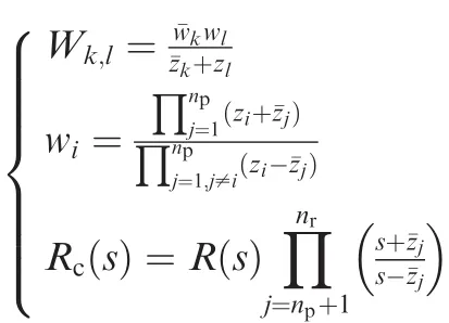
The reference command can be represented as a 1st order system with the bandwidth ωrassociated with no unstable zeros:

For a system with only one open right half plane zero,the value ofJ2is given by:

wherezdenotes the zero in the right half plane.It has been proved that the path track without speed assignment will remove this performance limitation on the L2norm of the tracking errors25,and this conclusion coincides with Eq.(14)by setting the bandwidth of ωrsmall enough.The norms of the tracking error will decrease as the decrease in the reference bandwidth.Therefore,a performance trade-off imposed by the open-loop system arises in order that the closed-loop system can track a quick target precisely.
3.3.Robustness specifications
Limits on the robustness,introduced in this section,include the lower bounds of peaks of the sensitivityS(jω)and complementary sensitivity functionsT(jω).Assume that the transfer functionL(s)regarding zeros and poles in the right half plane can be factored as

where~L(s)denotes the stable dynamics concerning the minimum phase behavior.Bz(s)is the Blaschke product of open zeros in the right half planezi(i=1,2,...,Nz),andBp(s)the Blaschke product of open poles in the right half planepi(i=1,2,...,Np).
Letzbe an open zero in the right half plane ofL(s).S(jω)must satisfy the following integral constraints for stability of the feedback system:

where λz(ω)=arctan[(ω -y)/x],z=x+jycan be regarded as a weight function with respect tozin the frequency domain.
The integral of the weight function in the frequency range Ω is called the weighted length,and denoted as

Suppose that the closed-loop system is stable and the level of sensitivity reduction is set to beSαwithin the bandwidth ω1:

For suppressing noise beyond the bandwidth ω2,specifications on the robustness also is expressed by

The H∞norm ofS(jω),denoted asMS=||S(jω)||∞,is a robustness index of the closed-loop system.For each open right half plane zero,the following bound must be satisfied with26:

where Ω′= ΩC1∩ [-ω2,ω2],ΩC1is the complementary set of ω1.
The inequality(20)indicates that a minimum value ofMS,related to robustness specifications in the frequency domain(Sα,ω1,ω2)and plant dynamicsBp(z),is independent of the control system design.If the level of sensitivity reduction is set to beSα=0.707,then ω1is equivalent to the bandwidth ofS(jω),denoted as ωB.An inherent trade-off between minMSand ωBemerges from the inequality(20).In addition,the conclusion forT(jω)is similar,and this reveals a tradeoff betweenMT=||T(jω)||∞and the bandwidth ωBT.
3.4.Synthesis of performance limitations
Performance limitations in the frequency domain and time domain are synthesized in Fig.2,where ωBdenotes the bandwidth ofS(jω),and ωBTthe bandwidth ofT(jω).ωr,ωarepresent the reference bandwidth and the actuator bandwidth,respectively.Dashed lines in Fig.2 imply that performance limits placed by plant characteristics and flight conditions are independent of the control system design.Dash-dotted lines represent control specifications on the robustness indexesMS,MT,tracking accuracy||e(t)||2,and the size of the null controllable region Δx.
The trade-off between the tracking accuracy min||e(t)||2and reference bandwidth ωrindicates a lower FPA bandwidth is preferred for tracking accurately.The bandwidth of a reference command ωr,such as FPA command,is determined by the trajectory.Meanwhile,the control bandwidth ωBof FPA should be larger than ωrto possess the good tracking performance.However,the control system will become more sensitive to output disturbances and model uncertainties with the increase in ωBandMS.Therefore,specifications on the robustnessMSin the frequency domain must guarantee that max ωB> ωr.
On the other hand,the size of the null controllable region is limited by an unstable plant dynamic and a control margin.Furthermore,the actuator bandwidth squeezes the null controllable region according to Eq.(12).Hence,the specification on stability requires a higher actuator bandwidth.In addition,the specification on the robustnessMTin the frequency domain defines a lower bound of bandwidth min ωBT,and this means that ωa> min ωBT.
Limits on the control performance are related to flight conditions of the hypersonic vehicle.Therefore,the constraints in the conventional trajectory design may be insufficient to obtain a feasible solution because of the disregard of the control performance.Specifications on stability,tracking accuracy,and robustness also affect constraints in the trajectory design,thereby narrowing down the flight corridor.Furthermore,a control-oriented model of the air-breathing hypersonic vehicle is provided to verify these performance limitations in the following section.
4.Simulation results
A control-oriented model of a dual-mode scramjet-powered hypersonic vehicle is developed to reveal the effects of control specifications on the ascent trajectory of AHSVs.27The model is an extensive work regarding Parker et al.28A set of ascent trajectories at a constant dynamic pressure ranging from 50 to 125 kPa is designed.First,the limits on the control performance are examined through the ascent trajectory at constant dynamic pressure of¯q=50 kPa.Second,other ascent trajectories are investigated to explore the variations in performance limits with regard to the dynamic pressure.Lastly,the effects of control specifications on the trajectory design are summarized.

Fig.2 Control performance limitations and trade-offs.
4.1.Optimal ascent trajectories
Four ascent trajectories regarding the constant dynamic pressure(Mafrom 5 to 8)have been optimized without considering constraints on the flight path angle rate.The optimal flight path angles for different trajectories are shown in Fig.3,and the consumed fuel masses of these ascent trajectories have been listed in Table 1.
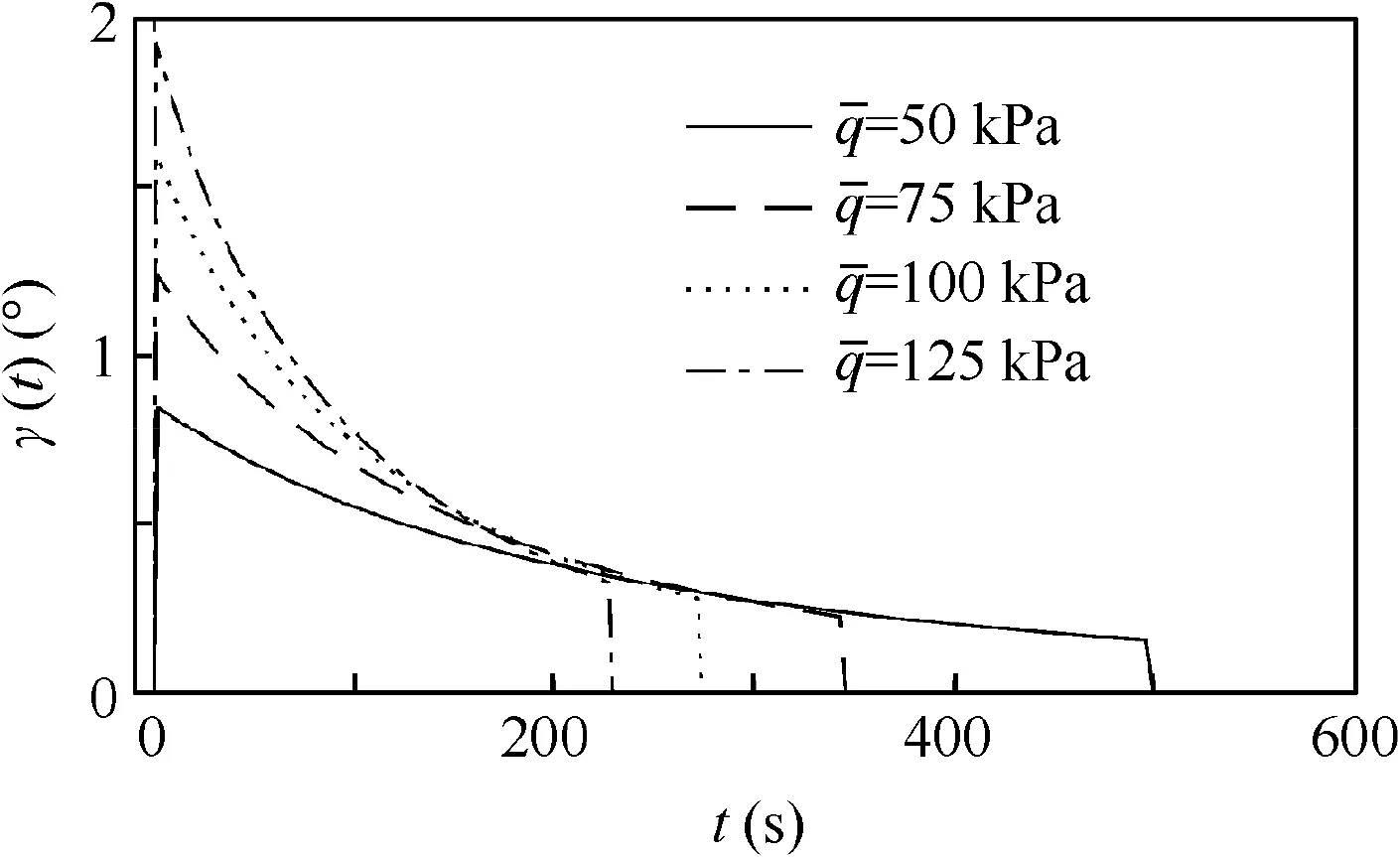
Fig.3 Flight path angles for trajectories at different dynamic pressures.

Table 1 Objective of optimal constant dynamic pressure climb.
The fuel mass consumed is non-monotonic concerning the dynamic pressure.Although the propulsive efficiency of the scramjet improves at a high dynamic pressure operation,the energy consumption due to the increased drag rises accordingly.

Fig.4 Control margin of elevator for different dynamic pressures.
The null controllable region is mainly affected by the unstable mode and control saturation.The saturation values of the deflection angle of the elevator are set to be ±15°.Then,the control margin,donated as δmargin,is defined as the gap between the current deflection of the elevator and its saturation.The control margin shrinks as the increase in the speed and the decrease in the dynamic pressure(see Fig.4).This circumstance will cause significant impact on the stability of hypersonic vehicles and take a challenge in the control system design.
4.2.Performance limits for ascent trajectory at 50 kPa
The linearized models through the ascent trajectory are obtained with the quasi-equivalent condition using the Taylor expansion at each node.The quasi-equivalent condition assumes that the pitch rate of the vehicle is zero at nodes.By calculating the performance limitations introduced in Section3,the control performance is spotted in the time domain and frequency domain(see Fig.5)wherein the gray regions represent the achievable performance.
The attitude stability is more sensitive to disturbances at high-speed flight since Δαacalculated by Eq.(11)tends to shrink as the velocity increases.Attitude regularization cannot be achieved due to the input saturation when the disturbance exceeds the range.The tracking error is closely related to the reference command determined by the trajectory.In addition,a fast FPA reference leads to a large tracking error,and the robustness of the control system reduces since the peaks ofS(jω)increases in the reference bandwidth.
From the perspective of the robustness,MS,MTconflict with the bandwidth of the closed-loop system.The max ωBand min ωBTare decided at a flight condition by robustness specifications(MS,MT<3.5).The corresponding bandwidth requirements on FPA and actuators are shown as solid lines in Fig.5.Results show that ωahas to be larger than 35 rad/s to satisfy the robustness specification throughout the flight.Besides,the bandwidth ωγdetermined by the designed trajectory(as dashed line in Fig.5(b))must locate beneath the bandwidth:ωγ< max ωγ=max ωB,where ωγ,refis the bandwidth of reference FPA from the designed trajectory.
If the control specifications are enhanced on the robustness required thatMS,MT<2 the corresponding results are illustrated by dash-dotted lines in Fig.5.ωais more than 60 rad/s throughout the ascent phase.Furthermore, flexible effects are introduced since the natural frequency of flexible mode is as low as 22 rad/s.13Besides,a higher requirement for the robustness reduces the maneuverability.The reference FPA bandwidth is beyond the range of max ωγ,thereby indicating that the control specificationMS<2 cannot be met for current ascent trajectory.Hence,some specifications on the control performance might be unachievable through the path.
4.3.Flight envelope analysis
In the previous section,performance limits regarding the velocity at constant dynamic pressure are discussed.The flight envelope can be parameterized by the dynamic pressure.Thus,performance limits with respect to dynamic pressure are examined.The extreme worst case about the velocity at constant dynamic pressure is assigned to be the performance limits at the dynamic pressure.
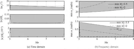
Fig.5 Limits on control performance through the trajectory.
The simulation results show that the range of admissible disturbances of the angle of attack Δαachanges from 13°to 2°as the variation in the dynamic pressure is from 100 to 25 kPa.The trimmed deflection angle of the elevator becomes larger at lower dynamic pressure to maintain the steady flight,thereby leading to the decrease in the control margin.As a result,the range of admissible disturbances of the angle of attack becomes narrow as the dynamic pressure decreases(see Fig.6).If the control system has to suppress the disturbance of the angle of attack up to 5°,the dynamic pressure for the hypersonic ascent should be greater than 42 kPa.
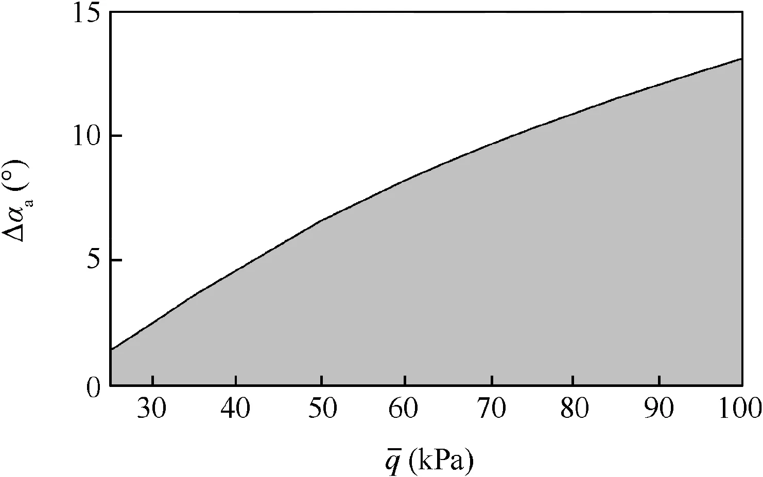
Fig.6 Maximum admissible disturbances of angle of attack with respect to dynamic pressure.
The high-speed flight of hypersonic vehicles requires a precise tracking control of FPA in case of flying out of the flight envelope.17A reference command of FPA with unity magnitude is used to analyze limits on the tracking accuracy regarding L and L2norm of the tracking error(see Fig.7).The inherent trade-offs are independent of the control system design and only determined by the plant dynamics and flight conditions.In conclusion,the tracking error increases with the decrease in the dynamic pressure and the increase in the bandwidth of reference command,and the reference bandwidth is the main factor that affects the tracking performance.
From the perspective of the robustness,the trade-off between the peak ofS(ω)and the closed-loop bandwidth ωBindicates that the maneuverability conflicts with the robustness.This inherent trade-off tends to be stricter as the dynamic pressure decreases(see Fig.8).Also,the relationship of FPA between the bandwidth and the dynamic pressure indicates that the smooth variation in FPA is preferred when considering the robustness,especially at lower dynamic pressure.
The maximum FPA bandwidth determined by the trajectory is assumed to be 0.7 rad/s,and the actuator bandwidth is set to be 20 rad/s to prevent elastic effects,which means min ωBT< 20 rad/s.The feasible range of the dynamic pressure is shown in Table 2.Specifications on the tracking accuracy are disregarded since the tracking performance is closely related to the designed trajectory.
Table 2 indicates that some specifications on the control performance cannot be achieved(MS<2.5,andMT<2.5).Under such circumstances,either control specifications compromise or the hypersonic vehicle is refined.Constraints imposed by the control performance(minMS<3.5,minMT< 3.5,max Δαa> 5°)are shown in Fig.9.The feasible operating range of the hypersonic vehicle is the intersection regarding these constraints.Thus,the ascent path at 40 kPa is an infeasible solution when considering the mission requirements with the control action.The simulation results suggest that the trajectory design should account for the constraints on the control performance to obtain a reliable solution.

Fig.7 Maximum admissible disturbances of angle of attack with respect to dynamic pressure.
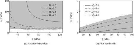
Fig.8 Bandwidth requirements for different robustness specifications.
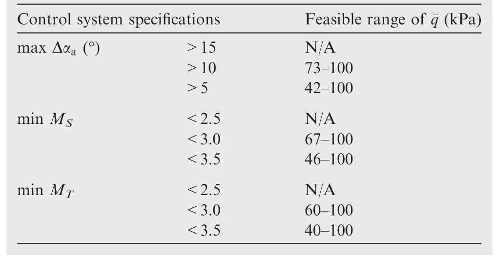
Table 2 Maximum feasible range of¯q with maxωγ=0.7 rad/s and ωa=20 rad/s.
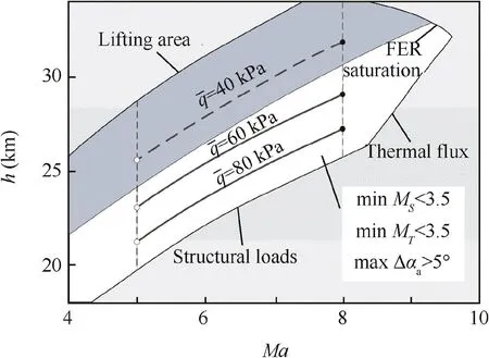
Fig.9 Flight envelope considering control specifications.
5.Conclusions
The performance limitations in trajectory tracking control for AHSVs are investigated.An integrated approach is proposed to account for stability,tracking accuracy,and robustness.
(1)Robustness is in conflict with tracking accuracy and maneuverability,and a comprehensive consideration of this performance should be adopted.These trade-offs and limits depend on the open-loop dynamics of AHSVs,indicating that the tracking performance of the control system is related to the designed trajectory.
(2)The performance limits in control system design are imposed by the plant dynamics and flight conditions.These limitations extend with the increase in the relative ratio of the non-minimum phase zero to the unstable pole.The control margin along the trajectory is another crucial parameter that affects the stability of AHSVs.
(3)Ascent trajectory is characterized by dynamic pressure.A set of ascent trajectories at a constant dynamic pressure is optimized by using a trajectory design method that considers the available acceleration.Longitudinal dynamics are highly unstable at a small control margin and low dynamic pressure.As a result,the limitations on control performance become increasingly strict.
(4)The null controllable region of longitudinal dynamics shrinks as the dynamic pressure decreases.The robustness and tracking accuracy of the control system deteriorate as well.The simulation results show that specifications on stability and robustness restrict the operating conditions of AHSVs to a high dynamic pressure and narrow down the flight envelope.
(5)The integrated analysis approach for hypersonic vehicles provides primary insights into the control-relevant performance of trajectory tracking and facilitates the design of reliable flight plans.Trajectory design for hypersonic vehicles should consider control-relevant performance to obtain feasible and achievable solutions due to the unstable dynamics with limited control authority.
Acknowledgements
This work was supported by Aerospace Science and Technology Innovation Fund of China(No.CASC2016)and Six Talent Peaks Project in Jiangsu Province of China(KTHY-025);Funding of Jiangsu Innovation Program for Graduate Education;the National Natural Science Foundation of China(Nos.61403191,11572149);the Funding of Jiangsu Innovation Program for Graduate Education of China(Nos.KYLX_0281,KYLX15_0318 and NZ2015205);the Fundamental Research Funds for the Central Universities of China.
杂志排行
CHINESE JOURNAL OF AERONAUTICS的其它文章
- Recent development of casing treatments for aeroengine compressors
- Recent advances in physical understanding and quantitative prediction of impinging-jet dynamics and atomization
- General aspects on structural integrity
- Design and simulation of an innovative cylinder fabricated by selective laser melting
- Application of reliability technologies in civil aviation:Lessons learnt and perspectives
- FEC design for remote control and data transmission of aeronautic and astronautic vehicles
