Recent advances in physical understanding and quantitative prediction of impinging-jet dynamics and atomization
2019-01-16XiaodongCHENVigorYANG
Xiaodong CHEN,Vigor YANG
aSchool of Aerospace Engineering,Beijing Institute of Technology,Beijing 100081,China
bSchool of Aerospace Engineering,Georgia Institute of Technology,Atlanta GA 30332,USA
KEYWORDS Computational fluid dynamics;Flow instability;Flow visualization;Gas/liquid interfacial dynamics;Impinging-jet atomization;Theoretical models;Two-phase flow
Abstract Impinging-jet injectors are widely used in liquid propulsion applications,since their simple configuration provides reliable and efficient atomization.The flow field involves a series of complicated spatio-temporal evolutions.Much effort has been directed toward understanding the underlying physics and developing quantitative predictions of impinging-jet atomization.This paper summarizes the recent advances in this direction,including state-of-the-art theoretical,experimental,and numerical studies,along with representative results.Finally,concluding remarks address remaining challenges and highlight modeling capabilities of high- fidelity simulations.
1.Introduction
Impinging-jet injectors utilize the collision of liquid jets to transform the liquid from jets to a sheet.Instabilities inherent in the liquid sheet then disintegrate the sheet into discrete droplets.The simplest,and most common,configuration is the collision of two identical liquid jets at an acute angle,commonly referred to as a doublet.Fig.1 shows a flow schematic,where the centerlines of the liquid jets intersect at an impingement point.This configuration has been widely used in liquidfueled propulsion engines.For example,the F-1 engine on the first-stage of the Saturn V launch vehicle in the Apollo lunarlanding project employed impinging-jet injectors in both the main combustion chamber and the gas generator.1Fig.2(a)shows the injection faceplate of the F-1 engine,where numerous orifices are configured to produce impinging jets.Fig.2(b)shows a snapshot from the water test of the combustor.

Fig.1 Schematic diagram of doublet impinging jets.
The impingement of liquid jets is a very efficient method for atomization and mixing,whereby the dynamic head of the jet is used to destabilize an opposing liquid stream.A rich variety of flow structures,from single oscillating jets at low flow rates to the violent disintegration of flapping sheets at high flow rates,have been observed under the influence of surface tension,viscous stress,inertial and aerodynamic forces.In addition to propulsion systems,impinging jets have been widely used in continuous microreactors for synthesizing nanoparticles,2,3liquid inhalers for respiratory drug delivery,4and high throughput production of monodispersed microemulsions/mi crosuspensions of various compositions,sizes,and shapes.5The impingement concept has also been implemented to reduce fuel consumption and exhaust emissions of diesel engines.6The pressure head for such applications,however,is usually high enough to cause direct atomization at the nozzle exit.The sprays from the two injection nozzles then interact.6This situation is beyond the scope of the present paper,which mainly deals with the formation and dynamics of liquid sheets,and subsequent atomization.
A number of theoretical,experimental,and numerical studies have been performed to illuminate the underlying physics of impinging jets,including jet disintegration patterns,thickness and flux distribution in liquid sheets,breakup mechanisms,and atomization characteristics.Analytical models have been developed for the thickness,7-9shape,7-9and velocity9of the liquid sheet,as well as the size distribution of the droplets detaching from the rim of the liquid sheet.10Experimental studies have been performed to measure the thickness,11-13shape,8,9,11,14and velocity14-16of liquid sheets,and droplet configuration and size.9,17A wide range of Reynolds and Weber numbers have been covered.Because of the complexity of such multiscale two-phase flow phenomena,however,only limited literature exists on numerical simulations that address detailed impinging jet dynamics.18-20
Under flow conditions typical of liquid-propellant rocket engines,the liquid sheet formed by impinging jets undergoes violent breakup caused by fast-growing instability waves,commonly referred to as impact waves.13,21Impact waves dominate the breakup and atomization processes.In this review,we focus on recent advances in the physical understanding and quantitative prediction of impinging-jet dynamics and atomization for liquid rocket engines.We begin our review with initial jet conditions,basic flow patterns,and hydrodynamic instability waves.Theoretical approaches using aerodynamics-based and impact wave-based models for full developed sheet breakup are then summarized.Next,state of-the-art experimental and numerical approaches are reviewed,to highlight paths towards quantitative prediction of the complex atomization process.Finally,existing issues and challenges are described,and potential solutions are suggested.
2.Flow physics
2.1.Initial jet conditions
The first stage of impinging-jet atomization is the ejection of the liquid jet.Jet behaviors greatly affect the formation and breakup patterns of the liquid sheet.A jet can be either laminar or turbulent,depending on the flow conditions in the distributor and injector nozzle,and the flow path between the nozzle exit and the impinging point.Fig.3 shows liquid water injected into air from a short and a long nozzle over a range of the Reynolds numbers,Rej.22The liquid jet appears to be smooth near the nozzle exit for both cases.The flow disturbances produced in the nozzle tend to grow faster at a higher Reynolds number and for a longer nozzle.22For many liquid impinging jets,such as those in rocket engines,the flow may become highly turbulent prior to the impingement point,due to the flow evolution in the injection head and sharp orifice edges.The jet is embedded with significant surface disturbance and may even be disintegrated,which of course has significant impact on the subsequent sheet formation and atomization.The inception and growth of surface instability in a liquid jet also depends on the ambient gas and pressure,p,as shown in Fig.4.23The instability becomes stronger with increasing pressure;this is attributed to decreased surface tension at elevated pressure.24
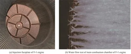
Fig.2 Employ of impinging-jet injectors in F-1 engine on the first-stage of Saturn V launch vehicle.
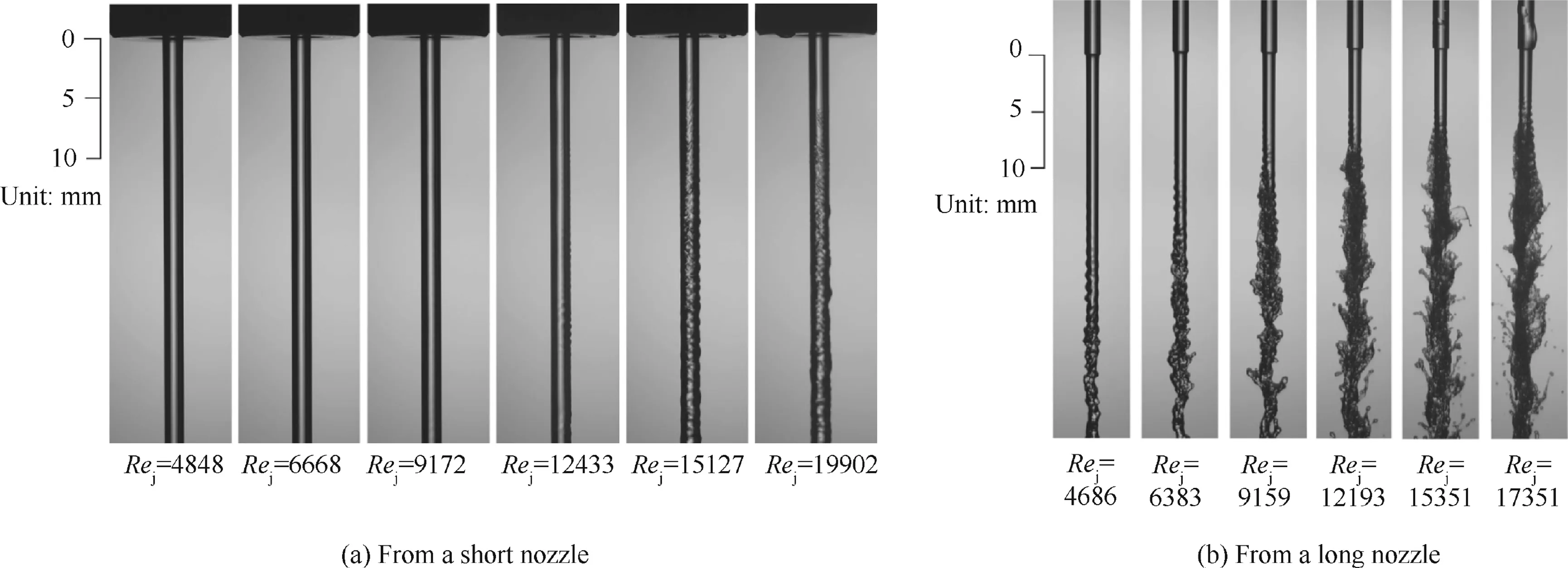
Fig.3 Liquid water jets in air from short and long nozzles.22
2.2.Basic flow patterns
The flow characteristics and atomization of impinging jets depend on the impingement angle 2α,the ratio of the preimpingement jet length to the jet diameter,the jet velocity profile,the turbulence level,and two nondimensional parameters:the Weber and Reynolds numbers.These numbers are defined,respectively,asWe= ρu2jD/σ andRe= ρujD/μ,where ρ is the liquid density,ujthe mean jet velocity,Dthe jet diameter,σ the surface tension,and μ the viscosity of the liquid.The ambient gas also plays an important role in the flow dynamics,through the aerodynamic force acting on the liquid/gas interface.23,25
Fig.5 summarizes five basic flow patterns obtained from high- fidelity numerical simulations for a glycerin-water solution in air.20,26The impingement angle 2α is 60°,a value widely used for liquid-propellant rocket engines for its effective atomization characteristics.Fig.5(a)shows a chain pattern with a relatively low velocityuj.The two jets coalesce into a single column that oscillates under the inertial-capillary interaction.Breakup takes place at the end of the column under the Plateau-Rayleigh type of instability.Asujincreases,a liquid sheet is established,as shown in Fig.5(b).The expanding liquid is collected at the boundary in the form of liquid rim under surface tension.This pattern is usually referred to as a closed rim.Fig.5(c)shows a situation known as open rim pattern.The thin liquid sheet in the downstream region is prone to small disturbances.Holes form and grow progressively,eventually causing the sheet boundary to open at the rim.As the jet velocity further increases,the liquid rim becomes unstable,as shown in Fig.5(d).Disturbances originating at the impingement point grow and propagate downstream along the liquid rim.The rim becomes unstable under a capillary instability of the Plateau-Rayleigh type because of its cylindrical crosssection,and a centrifugal Rayleigh-Taylor type because of its curvature.9This type of pattern is also referred to as the unstable rim pattern.In the extreme case of highuj,shown in Fig.5(e),the liquid sheet becomes unstable and undergoes violent flapping,followed by rapid atomization into liquid ligaments and even droplets.This is so-called the impact wave pattern.A movie showing the flow evolution of the various patterns is presented in Ref.26.
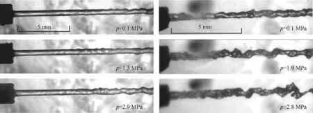
Fig.4 Liquid water injected into air(p=0.10 MPa)and nitrogen(p∈[0.1,2.9]MPa).23

Fig.5 Impinging-jet flow patterns of glycerin-water solution in air from simulations20(comparison movies showing flow development given in Ref.26,D=400 μm,2α =60°).

Fig.6 Complex impinging-jet flow patterns.
In addition to the Weber and Reynolds numbers,the evolution of the liquid sheet and the subsequent atomization are influenced by the impingement angle and the turbulent intensity of the liquid jet,as well as the density ratio of the ambient gas to the liquid.There exist patterns with various degrees of complexity as compared to the basic patterns.Fig.6(a)shows an unstable rim pattern accompanied by concentric unstable or aerodynamic waves for 2α =90°.22The waves form under the Kelvin-Helmholtz(K-H)instability,which occurs when the sheet velocity relative to the ambient medium is large enough to initiate and sustain unstable waves through shear stress.27The undulated sheet breaks into liquid ligaments and subsequently droplets,similar to the disintegration of liquid sheets formed by single-hole fan spray nozzles.28For a relatively larger impingement angle of 120°,the undulated sheet can break into droplets under so-called ‘‘wavy corridor” mechanisms.This atomization pattern relies on transient acceleration imparted to the sheet involving a centrifugal instability of a Rayleigh-Taylor type,modified by the finiteness of the sheet thickness.29Fig.6 (b)shows a typical example for 2α =120°.23Both transverse and longitudinal wrinkles are observed over the lower periphery of the liquid sheet,and are closely related to the formation and ejection of droplets.
2.3.Dominant instability waves
It was realized in the 1950s that a liquid sheet formed by impinging jets breaks under two larger-scale waves with aerodynamic and hydrodynamic origins.30,31A relatively flat liquid sheet breaks in the downstream region due to aerodynamic waves,while hydrodynamic(or impact)waves are produced at the point of impingement.13A direct proof of the hydrodynamic origin is that impact waves have been found to exist in vacuo(93.5%vacuum,6.7 kPa);this indicates that they are not caused by aerodynamic forces,but result from the impact of the two jets.13The occurrence of aerodynamic and impact waves depend on the jet velocity,impinging angle,and flow characteristics(laminar or turbulent).Fig.7(a)shows the aerodynamic wave in the downstream region of a liquid sheet formed by impingement of two laminar jets.25Impact waves also appear near the impingement point,but are damped out rapidly.In addition,they are more pronounced near the axis of the sheet,since the liquid mass concentrates in that region,in the inclined impact of the liquid jets.For two turbulent jets,impact waves are amplified to quickly cause flapping of the liquid sheet near the impingement point,as shown in Fig.7(b).25The liquid sheet breaks up into ligaments and then droplets.Note that the aerodynamically-induced surface shear stress can also generate waves if the liquid sheet does not disintegrate from impact waves(see Fig.7(a)).The presence of both aerodynamic and hydrodynamic waves produces intricate jet breakup and atomization processes,involving a wide range of length scales.
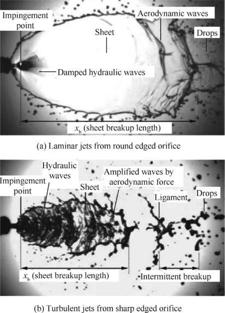
Fig.7 Sheet formation by impingement of water jets in nitrogen at 2.1 MPa for uj=7 m/s.25
Previous experiments have shown that violent disintegration of impinging jets generally results from the formation of instability waves of aerodynamic or hydrodynamic origins.The characteristics of the former are fairly well understood by means of linear stability analyses that take into account the interfacial interactions between liquid and gas.Little is known,however,about the latter.It was found31that the latter wave frequency of the sheet breakup increases with increasing injection velocity and decreasing impingement angle.Further,the jet diameter and length before impingement have a negligible effect on the wave frequency.For impingement angles in the range of 50°-100°,the frequency increases linearly with the resultant jet velocity in the plane of the sheet,as shown in Fig.8.Anderson et al.21revealed that impact waves are formed with a characteristic wavelength of about one jet diameter.Results from a computational study of the flow structure around the stagnation point showed that the effects of impingement extend about one jet diameter upstream,and that the maximum gradient and incipient disruption of the surface occur at a normalized radius of 1.2,where an inflection in the jet flow from predominately axial to predominantly radial occurs.Chen et al.20investigated the flow evolution in the entire field.The axial velocity profile on the center cross section of the liquid sheet was found to be parabolic immediately before the formation of the impact wave.As observed by Sander and Weigand32in their study of a single liquid sheet,the velocity profile has a profound effect on the sheet stability characteristics,leading to a flapping pattern similar to the one observed in an impinging-jet-formed sheet.The wave frequency can be expressed as f=us/λ,where usis the characteristic velocity of the liquid sheet and λ the wave length.The Strouhal number for the impact wave can thus be defined as,St=fD/us=D/λ.As mentioned above,impact waves also exist at low Weber numbers,but have damped amplitude in space(Fig.5(d)).Fig.9 summarizes St for a wide range of We for 2α =60°.20Chen et al.20found that St increases linearly with increasing We,and levels off at a constant value of about 0.835 for We>1000.A similar phenomenon has been observed in perturbed free shear layers.33-35This suggests that the flow mechanism of the impact wave is analogous to that of the free shear layer.The interaction between the two shear layers is believed to be the primary cause of the wave dynamics after jet impingement.20
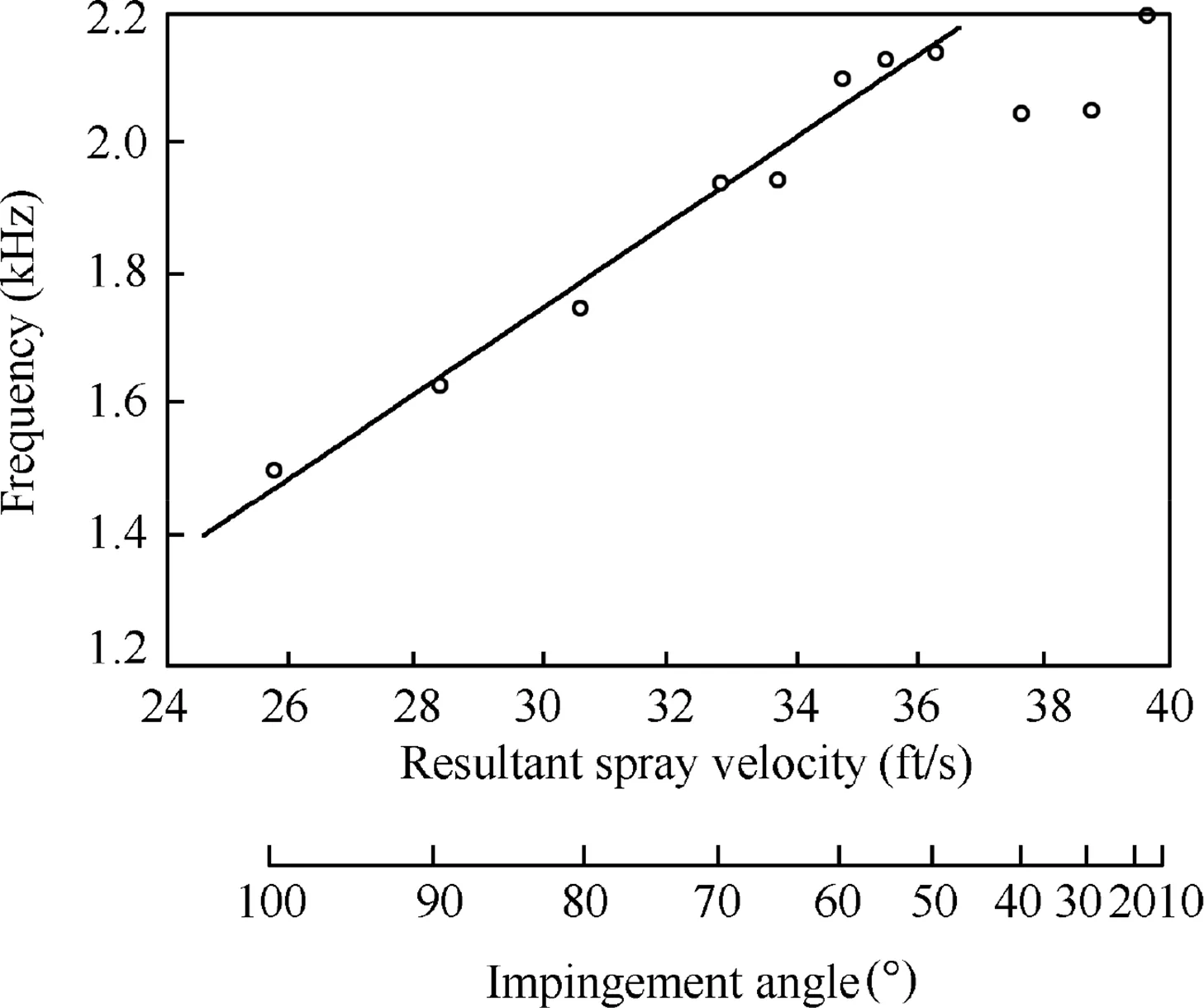
Fig.8 Effect of impingement angle on wave frequency of fully developed sheet of water(1 ft=304.8 mm).31
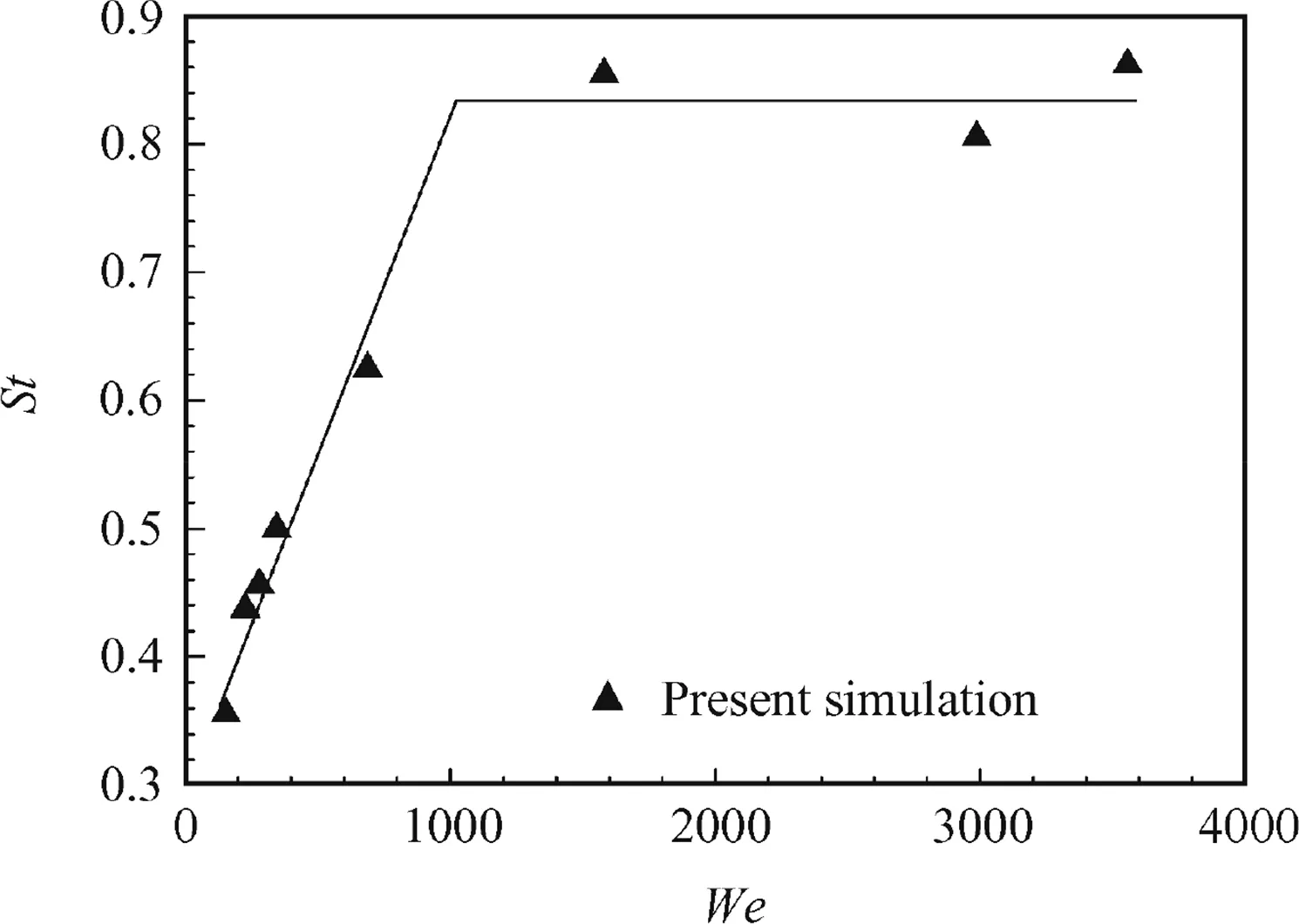
Fig.9 Strouhal number of impact wave with different Weber numbers.20
3.Theoretical studies
3.1.Aerodynamic-based models
Similar to other types of injectors(such as fan,swirl,and spinning cups),liquid sheets formed by impinging jets can fragment into ligaments,which eventually break up into droplets,due to the formation of aerodynamic waves.Linear stability analysis is a powerful tool to predict the growth of aerodynamic waves on the sheet,by considering the behaviors of infinitesimal disturbances under the influence of shear stresses on the liquid sheet.There are two different types of waves,sinuous(antisymmetric)and dilatational(symmetric)waves.36Since sinuous waves grow faster than dilatational waves,37only the behavior of sinuous waves should be considered,as shown in Fig.10(a).38Linear stability analysis calculates growth rates over a spectrum of wave numbers.The disturbance with the wave number corresponding to the maximum growth rate dictates the breakup process.Dombrowski and Johns39carried out a pioneering study that predicts droplet size based on linear stability analysis for fan-spray nozzles.The connection between the aerodynamic waves and the droplet size is shown schematically in Fig.10(b).Waves grow on the sheet until they reach a critical amplitude when tears occur in the crests and troughs.The fragments of the sheet corresponding to one-half wavelength break up.The fragments contract by surface tension into unstable ligaments,which subsequently lead to the formation of droplets.39Linear stability analysis can predict the amplitude of the disturbance along the propagation of the liquid sheet.The critical disturbance amplitude for sheet disintegration,however cannot be predicted in this way.A previous study on liquid sheets produced by fan-spray nozzles40showed that the total growth has a constant value of 12,independent of operating conditions.The diameters of liquid fragments are thus obtained from mass conservation.The analytical model of Weber41can be applied to give the relationship between the ligament diameter and resulting droplet diameter.The liquid sheet formed by impinging jets is distinguished from other types of liquid sheet by the spatial distribution of sheet thickness.The analytical expression of Hasson and Peck7is commonly used to describe the attenuating sheet thickness.
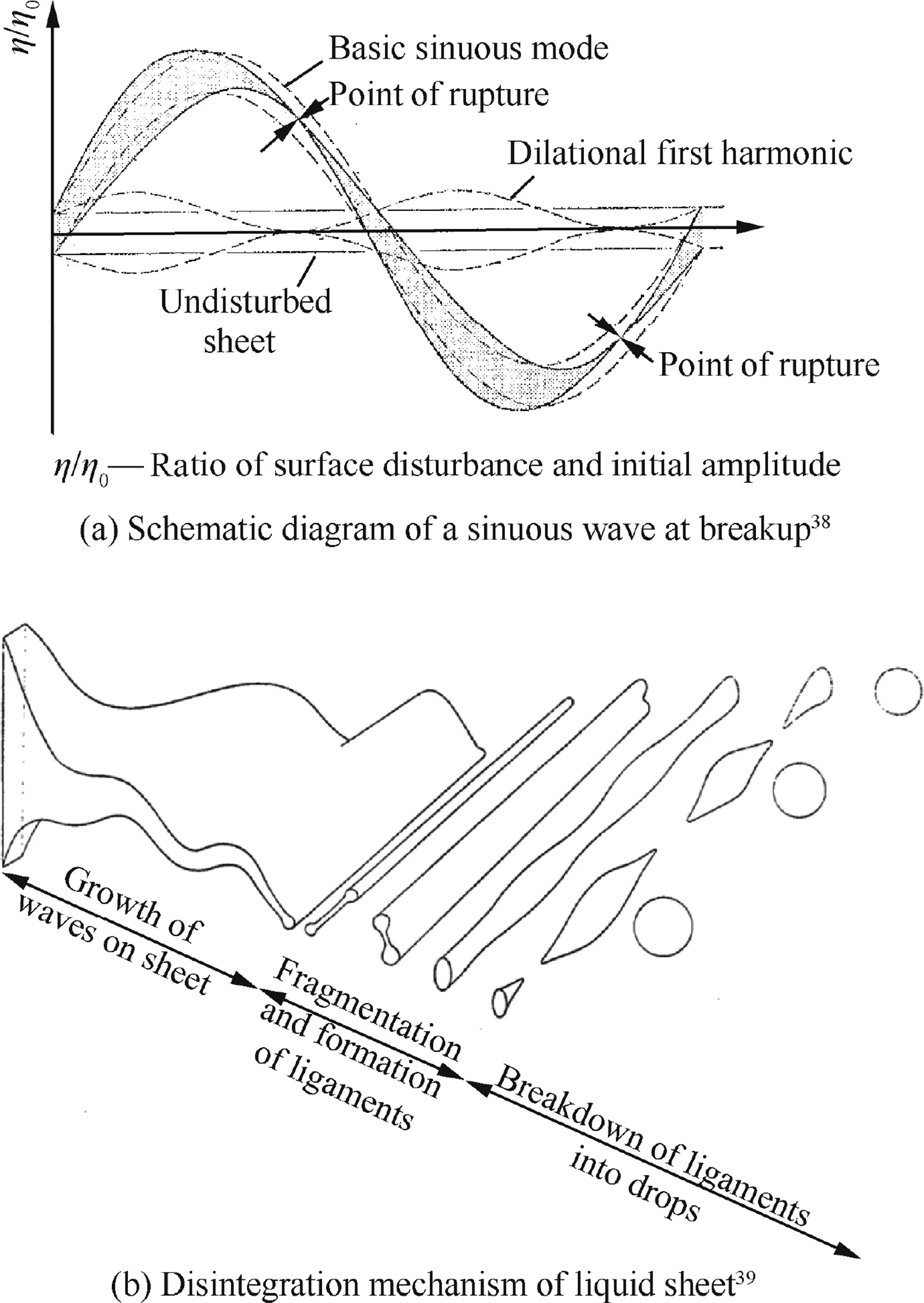
Fig.10 Schematic diagrams of unstable waves and disintegration mechanism of liquid sheet.
Based on the expression suggested by Dombrowski and Johns,39several theoretical models have been proposed to predict the mean droplet size of impinging jets under a variety of operating conditions.The models consider more realistic situations,such as viscous effects42and variations of sheet thickness.43The aerodynamic-based models are semi-empirical,since an empirical value for the critical disturbance amplitude for sheet breakup is required.Models based on linear stability analysis have shown more accurate prediction of sheet breakup and droplet sizes for relatively low-speed laminar impinging jets,but not for high-speed or turbulent jets.36In most rocket combustors using impinging jet injectors,impact waves dominate the atomization process.21
Ibrahim and Outland44employed a second-order nonlinear perturbation analysis to predict the characteristics of sprays produced by impinging jets.The evolution of harmonic instability waves that lead to sheet distortion and fragmentation was modeled.The analysis considered the onset of atomization when the uneven surface modulations of the thinning sheet bring its upper and lower interfaces in contact.Ibrahim and Outland44further confirmed that the sheet is torn into ligaments at each half wavelength.The sheet breakup length,time,and resultant droplet size decrease as the Weber number increases.Results show good agreement with available experimental data and empirical correlations for sheet breakup length and droplet size.The analysis,however,indicates that aerodynamic-based models do not render reliable predictions of turbulent impinging-jet atomization at high Weber number.45The impact wave generation process at the jet impingement point needs to be incorporated into the theoretical models to address this issue.36
3.2.Impact wave-based models
To predict the droplet size for atomization dominated by impact waves,Anderson et al.21developed a three-step phenomenological model using numerical observations,experimental measurements,and existing correlations for breakup length and droplet size.They carried out numerical simulations using an existing code,RIPPLE,46to gain insight into the flow behaviors in the stagnation region in the flow field and evaluate effects of the pre-impingement flow condition on the formation of impact waves.Simulations of axisymmetric impingement of two water jets under atmospheric conditions were performed.The work took into account three consecutive processes:formation and propagation of the impact wave,ligament shedding,and ligament disintegration into droplets.
The average size of the ligaments shed from the leading edge of the liquid sheet,dLwas determined from the wavelength of the impact waves λ and the sheet thickness at the breakup point,hb.

The sheet thicknesshbat the breakup pointxbwas obtained from Hasson and Peck’s analytical expression7for the thickness distribution of an undistorted liquid sheet formed by impinging jetsf(α)

where φ represents angular position.To account for the dependence of λ onxb,a correlation was developed from the calculated and measured wavelength data

Sincexbchanges with the ambient pressure or the density ratio,a correlation forxbwas proposed as

where κ is the density ratio of gas density to liquid density.The above equations yields an expression fordL.At the sheet centerline,φ=0,the ligament diameter is

The final modeling step is to relate the mean droplet diameterdDtodL.A correlation was established by combining Eq.(5)and existing correlations47for droplet diameter as a function of impinging jet geometry and flow conditions.Fig.11 shows the predicteddD/dLagainst the ligament Weber number based on gas density(Weg,lig)(the meanings of variables in Fig.11 can be referred in Ref.21).Good results are obtained over a range of ambient pressures from 0.1 to 1.05 MPa.
Recently,Han et al.48developed a theoretical model to describe data obtained experimentally.Based on the disintegration mechanism of Dombrowski and Johns39,the breakup of the liquid sheet formed by impinging jets is dependent only on the fluid properties and jet conditions,while the influence of the ambient gas is negligible.The wave number of the most unstable waveKmis written as a function of the impingement angle 2α,Reynolds numberRe,and Ohnesorge numberOh.The wavelength with the maximum growth rate takes the following form.

wherehis sheet thickness,C1,aandbare constants.The mass conservation for the ligament formation leads to an expression for the diameter of the ligamentdL

where,Kis sheet thickness parameter andC2is a constant.The relationship betweendLand the resulting mean droplet diameterdDcan be expressed using Weber’s results41for surfacetension controlled breakup as38

whereC,a,andbare constants determined from comparison with experimental data.Note thatK/D2is a dimensionless sheet thickness parameter from Hasson and Peck.7A generalized mean droplet diameterdD*can be defined as
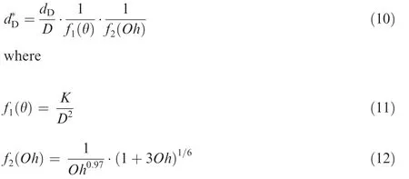
Fig.12 shows good agreement with measurement for three impingement angles over a wide range ofReandOh.

Fig.12 Comparison of measurement results with theoretical predictions for different fluids and impingement angles.48
4.Experimental studies
High-speed continuous and single-exposure photography are two widely-used approaches to visually study the flow structures and dynamics of impinging jets.Earlier experimental studies focused on the breakup patterns,frequencies,and lengths of instability waves on liquid sheets,and the sizes and velocities of resulting droplets.Advances in laser instruments for spray diagnostics have made the measurement of droplet sizes and velocities feasible and reliable.Most existing experiments focus on the droplet distribution in the downstream region.There still remain gaps in understanding the atomization process,from jet impingement through ligament disintegration to droplet formation.Several studies have,however,been performed to provide a detailed understanding of impinging-jet atomization.Choo and Kang15analyzed the velocity characteristics of liquid ligaments formed by highspeed impinging jets using a photographic double-pulse image capturing technique,which analyzed the pulse images of ligaments at two times,as shown in Fig.13.The maximum velocities of ligaments and droplets around the axis of the spray are close to the corresponding jet velocity;this is consistent with the common assumption that the velocities of liquid fragments are equal to the jet velocity.The shedding angles of liquid fragments increase linearly,but at a value slightly lower than the azimuthal angle,implying that the direction of the liquid movement is almost radial about the impingement point.A more refined theoretical work on the spray velocity is needed,since the velocities of liquid ligaments are affected by the impingement angle and local flow conditions and do not follow a uniform distribution across the region.
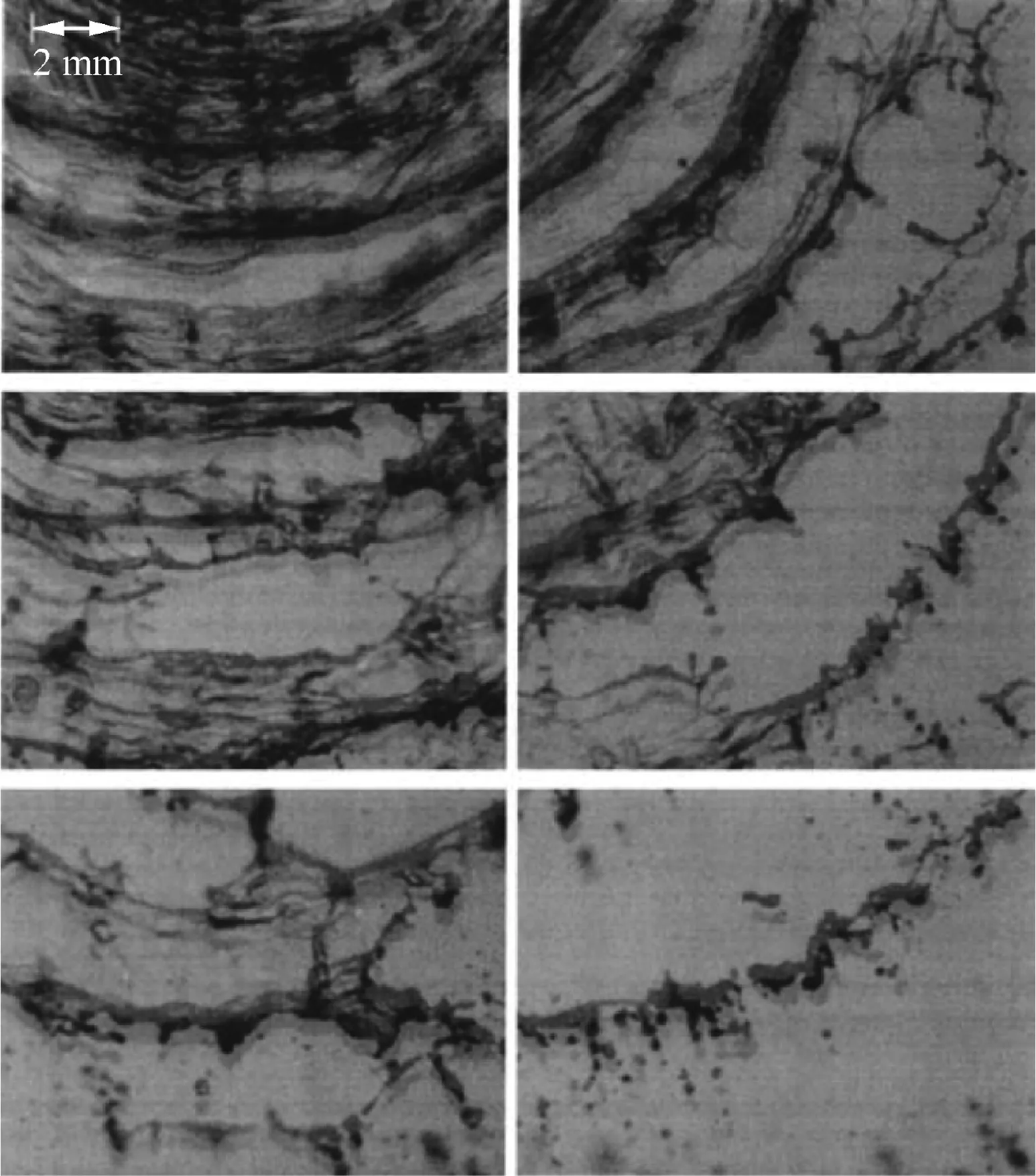
Fig.13 Double-pulsed photographs showing irregular arcshaped ligaments from impinging jets.15
High-magnification shadowgraphy with short laser backlight illumination(5 ns)was recently applied to study the dense region of a spray formed by impinging jets.49Fig.14 shows images from the impingement point to the downstream region,covering both the dense and dilute regions of the spray.Zis the distance from the impinging point andd0is the diameter of the injector orifices.The inner spray structure is clearly visualized,along with the measurements of droplet size,velocity,and shape inside the dense spray.The distribution of droplet size was recorded along the spray centerline and compared with a standard method for spray characterization,such as Phase-Doppler Interferometery(PDI).Small quantitative differences were observed.Various shapes of droplets and ligaments were observed,especially non-spherical droplets,most of which could be detected by an elliptical interpolation.It is worth noting that large largest droplets should be characterized by elliptical shapes,as they may be rejected by PDI.
5.Numerical studies
Jet impingement and the ensuing atomization involve extremely complex spatio-temporal evolution of gas/liquid interfacial flow motions over a broad range of time and length scales that may vary by several orders of magnitude.It is a formidable challenge to develop and implement experimental methods capable of characterizing such intricate flow dynamics.High- fidelity modeling and simulation techniques are thus required to help explore the underlying physics and identify key parameters dictating the flow evolution.
5.1.Eulerian-Eulerian approach
In the Eulerian-Eulerian numerical framework,the gas and liquid phases are treated using the same conservation equations,and the phase identification is achieved by a continuous function of volume fraction.For example,Inoue et al.50used a CIP-LSM(Constrained Interpolation Profile-based Level-Set and Multi-interface advection and reconstruction solver)method51to simulate impinging-jet atomization in a polar coordinate system.It was found that the jet velocity profile has profound effects on the stability of the liquid sheet and subsequent atomization.
Chen et al.20carried out high- fidelity numerical simulations to study the formation and fragmentation of liquid sheets created by two impinging jets,using an improved Volume Of Fluid(VOF)method augmented with Adaptive Mesh Refinement(AMR).52In order to resolve the multiple-length-scale phenomena during sheet development and atomization,gradient-,value-,and thickness-based AMR criteria were utilized simultaneously to improve the computational efficiency and robustness.The thickness-based criterion53was oriented by the topology of the gas/liquid interface to increase grid resolution with decreasing sheet thickness.This criterion was developed specifically for resolving liquid sheets with a large variation of thicknesses and complex topologies with thin structures.Chen et al.20validated the code against experimental results on various flow patterns of impinging jets over a wide range of Reynolds and Weber numbers.A post processing ray-tracing technique54was also implemented to obtain direct insight into the flow dynamics.Fig.15(a)shows the spray field of two water jet impingement.The corresponding Weber and Reynolds numbers are 2987 and 11724 respectively.The finest grid resolution is about 21 μm.Detailed flow physics of jet impingement,sheet flapping,ligament formation,and droplet detachment are clearly observed.To further explore the dynamics of the impact wave,the flow field was clipped from the center to show the cross-section in Fig.15(b).55Three-dimensional information on the impact wave and associated atomization dynamics are examined in depth to enable both quantitative and qualitative analyses.
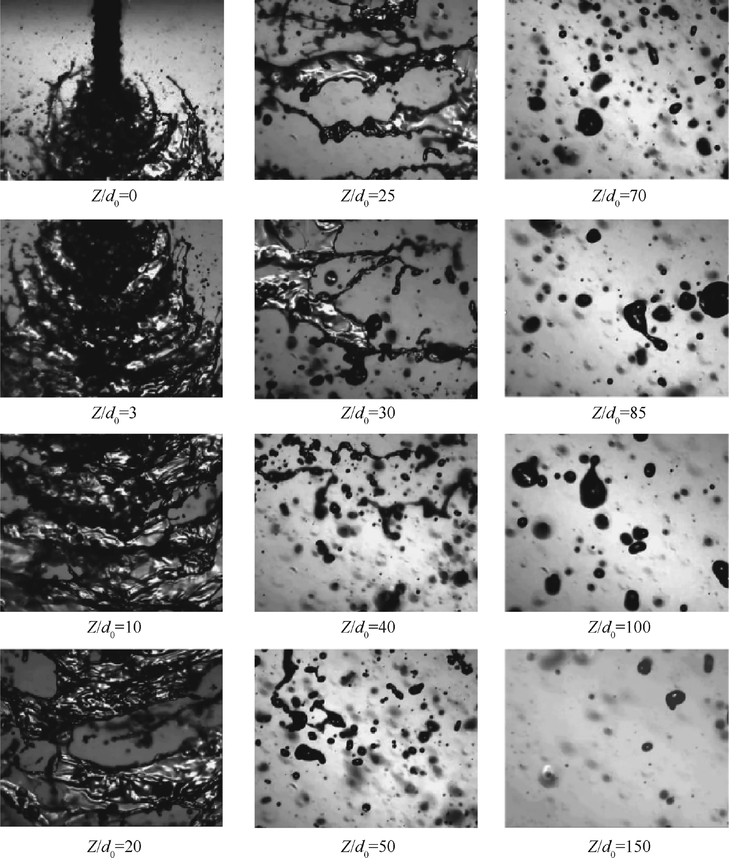
Fig.14 Shadowgraphs of impinging-jet atomization with short laser backlight illumination(5 ns).49
5.2.Eulerian-Lagrangian approach
The Eulerian-Lagrangian approach describes droplet behaviors with a Lagrangian formulation and gas-phase behavior with a Eulerian formulation.In this framework,primary atomization is calculated using models that can provide information about droplets.The droplet velocities,diameters,and distributions,obtained from experimental measurements for a specific injector,are typically specified at the impingement point as a fixed boundary condition.56,57The impingement process is excluded from simulations.The influence of the gas flow is also ignored in most models.The displacement of the impingement point and off-center impingement introduced by the gas flow thus cannot be predicted.58This type of approach is referred to as an uncoupled model.A coupled model has been recently developed to describe the jet impingement,with the effect of ambient conditions on the impinging spray.58The model is comprised of three sub-models:plain orifice,jet impingement,and droplet collision.In the jet impingement sub-model,a spatially uniform droplet size distribution is assumed,since the variation of droplet diameter along the sheet is negligible at high Reynolds number.59Experimental correlations36are employed to give the arithmetic mean diameter of the child droplets,which has a Rosin-Rammler diameter distribution.Droplet velocity magnitude and angle are also described in the jet impingement sub-model.Fig.16 shows the front and side views of the spray fields for two different impingement angles.Good agreement between calculated and measured mass flux distributions is achieved.60The coupled model shows more reasonable spray characteristics than the uncoupled model in both the start-up and steady-state phases of engine operation.The model can be further refined for more complex conditions through calibrations with experimental data.58
5.3.Coupled Eulerian-Eulerian and Eulerian-Lagrangian approach
The Eulerian-Eulerian approach requires considerable computational resources when dealing with an atomization process that involves wide spectra of time and length scales.The Eulerian-Lagrangian approach is more efficient,but relies on experimental data to specify the droplet conditions at the impingement point as the initial condition.The subsequent droplet evolution is also treated empirically.A feasible way to improve computational efficiency and accuracy is the coupled Eulerian-Eulerian and Eulerian-Lagrangian approach.For example,Tomar et al.61combined a VOF algorithm with a two-way coupling Lagrangian model to simulate droplet dynamics.Small droplets needing high grid resolution are transformed into Lagrangian particles,as shown in Fig.17.61Lagrangian particles were converted back into a VOF-resolved droplet based on its proximity to the VOF interface or a pre-specified region.Collisions between two droplets are predicted efficiently using a spatial-hashing algorithm.The coupled approach has been demonstrated to substantially improve simulation efficiency and accuracy for high-speed impinging-jet atomization.62Fig.18 shows snapshots of the spray field obtained from the Eulerian-Eulerian and coupled approaches.Under-resolved droplets are converted to Lagrangian particles to reduce the computational cost.The coupled Eulerian-Eulerian and Eulerian-Lagrangian approach can thus improve overall numerical accuracy indirectly for the same computational cost.
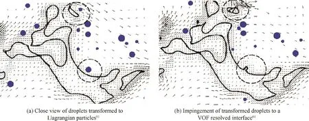
Fig.17 A two-way coupling method combining a VOF algorithm and a Lagrangian model to simulate droplet dynamics during atomization.

Fig.18 Comparison of simulation results obtained by two approaches.
Arienti et al.19applied a Combined Level-Set and Volume-Of-Fluid(CLS/VOF)formulation63along with a Lagrangian spray tracking approach to simulate impinging-jet atomization.Under an appropriate set of criteria,the conversion of droplet representation from an Eulerian to a Lagrangian framework enabled the simulation of sprays in a large domain with an extended time duration without degrading the overall accuracy of the calculation.Such a one-way coupling approach was implemented to study doublet impinging-jet atomization with different jet velocities.Results were validated against with experimental data.36,64
6.Concluding remarks
This paper reviews recent advances in physical understanding of and quantitative predictions of impinging-jet atomization for liquid propulsion applications.Emphasis is placed on the underlying flow physics and key parameters and conditions that dictate the spatio-temporal evolution of the flow field.
Impinging-jet atomization features a series of complicated dynamics,involving jet impingement,sheet formation,initiation and propagation of aerodynamic and hydrodynamic instability waves,sheet disintegration into ligaments and subsequent atomization into droplets,and droplet motion,in both dense and dilute spray environments.In spite of the development of experimental diagnostic techniques,it is a formidable challenge to measure the flow dynamics with resolution sufficient to identify the intricate gas/liquid interfacial motions and droplet motions.The situation becomes even more challenging under conditions typical of practical engine operation,in which the length and time scales may vary by several orders of magnitude.High- fidelity simulations appear to be a viable option to circumvent the obstacles.Three different modeling techniques(Eulerian-Eulerian,Eulerian-Lagrangian,and coupled Eulerian-Eulerian and Eulerian-Lagrangian)are discussed and accessed.Sample results are presented to illustrate modeling capabilities and dominant flow phenomena in impinging-jet atomization.
Acknowledgements
This work was sponsored partly by the National Natural Science Foundation of China(Nos.11772343 and 11402274)and partly by the Beijing Institute of Technology Research Fund Program for Young Scholars.
杂志排行
CHINESE JOURNAL OF AERONAUTICS的其它文章
- Recent development of casing treatments for aeroengine compressors
- General aspects on structural integrity
- Design and simulation of an innovative cylinder fabricated by selective laser melting
- Application of reliability technologies in civil aviation:Lessons learnt and perspectives
- FEC design for remote control and data transmission of aeronautic and astronautic vehicles
- Performance limitations in trajectory tracking control for air-breathing hypersonic vehicles
