General aspects on structural integrity
2019-01-16XIONGSHENOI
J.J.XIONG,R.A.SHENOI
aSchool of Transportation Science and Engineering,Beihang University,Beijing 100083,China
bFaculty of Engineering and Environment,University of Southampton,Southampton SO17 1BJ,UK
KEYWORDS Composites;Fatigue;Fracture;Reliability;Repair;Structural integrity
Abstract This paper seeks to mark the fruitful collaborative research between scholars in the University of Southampton and Beihang University for last 25 years on structural integrity.Their efforts addressed some important issues in structural integrity such as fatigue and fracture behavior,fatigue load spectra,fatigue and fracture lifetimes,reliability-based service period,adhesively bonded composite patch repairs,Plain Woven Fabric(PWF)composites and composite artefacts.New advances in engineering approaches,experimental methods,numerical algorithms and understanding of failure mechanisms relating to structural integrity are highlighted.Probable limits(or drawbacks)are also discussed.This review provides an insight into the general aspects on structural integrity and constitutes a basis for pointers to the further works on structural integrity.
1.Introduction
It has been reported1that 80%-90%of failures in loadcarrying engineering artefacts were attributed to fatigue and fracture.Accordingly,fatigue reliability analysis now is widely applied in the safe operation design for such artefacts.Fatigue loads on engineering artefacts lead to the onset of damage,which necessitate timely inspections,maintenance and repair.The key is to avoid repair that takes an artefact out of service.Occasionally,there exists a likelihood of sudden and catastrophic failure,if the damage has not been isolated at the early stage.Needless to say,it is crucial to precisely determine service lifetimes and inspection periods for ensuring safety.In practice,it has been proved that owing to the stochastic nature of fatigue loading on an artefact as well as the heterogeneity of structural material and the variability of manufacturing,fatigue lifetime almost always shows a large variation for the same nominal style of artefact under the same loading conditions.Therefore,it is infeasible for a deterministic approach to assess the aforementioned randomness and the service lifetime of an engineering artefact.Thus,there is a need for probabilistic methodologies incorporating mechanics and probabilistic statistics.
2.Fatigue and fracture behaviors
2.1.Deterministic fatigue and fracture behaviors
Fatigue cracks almost always occur around inclusions on a surface of metallic material.TheS-Nfatigue and the da/dN-ΔKcrack propagation properties have become the important material properties for depicting fatigue crack initiation and propagation for constant amplitude loading.Various empiricalS-Nfatigue and da/dN-ΔKcrack propagation property functions have been devised in the literature.The Basquin’s model is a three-parameter power function that commonly characterizes theS-Nfatigue property of material due to its superior fit for the medium-and long life ranges,better fitting precision than two-parameter power models,as well as with less experimental data than a four parameter power function.In order to consider the effect of stress ratio on theS-Ncurves,theS-N-Rfatigue property surface of a material was crafted by using the Basquin’s model in the power function with three-parameter and empirical constant-life diagram.2-4

whereSais the nominal stress amplitude;S0is the fatigue endurance limit fitted from experimental dataset;Nis the number of stress cycles to fatigue failure;σbis the material’ultimate strength;andRis the stress ratio;Candmare the material’constants.
On a macroscopic level,crack growth behavior is dependent on mechanical properties and thickness of material,crackorientation relative to the material’s principal directions,cyclic stress level and loading conditions.The Paris model is suited only for the linear or stable crack growth rate range,though not for all possible stress intensity ranges.The Trantina-Johnson model is apt for the linear or stable crack growth rate range and the near threshold region.Nevertheless,both models are valid only for specific stress ratios.The Walker model,a slight modification to the Paris model,is effective for the linear or stable crack growth rate range and for different stress ratios,but not for the near threshold region.Furthermore,the Forman model is valid for unstable and stable crack growth rate ranges for different stress ratios,but not for the near threshold region.The four parameter generalized Forman model requires a large sample size of experimental data to estimate four parameters,although it covers the full-range of the da/dN-ΔKcurve and fitting accuracy is the best.In order to effectively and conveniently depict crack growth behavior,a modified model incorporating the Walker and Trantina-Johnson the models was presented for the linear or stable crack growth rate range and the near threshold region and for different stress ratios.5

whereais the crack length/size;da/dNis the crack growth per stress cycle;ΔKis the stress intensity range;m1andm2are the material’constants;and ΔKthis the fracture threshold.
In practice,the critical parts of a structure(e.g.,turbine disc and blade,etc.in advanced aero-engines)often suffer from substantial oscillating loads with high loading frequencies,high stress ratios(or high mean stresses)and small stress amplitudes covering the Very High Cycle Fatigue(VHCF)regime at elevated temperature.For some metallic material(e.g.,low-and high-strength steels,and titanium alloys),experimental results from the High Cycle Fatigue(HCF)to VHCF regime followed a stepwise curve form in theS-Ndiagram.That is,fatigue strength first decreased from low to medium cycle regime,followed by a plateau to the classical fatigue endurance limit within the HCF regime,and ending with a further decrease within the VHCF regime.6-8However,no practical and valid mathematical function with the stepwise curve feature has been presented to depict fatigue property ranged from HCF to VHCF regime in theS-Ndiagram so far.
2.2.Probabilistic fatigue and fracture behaviors
Various probabilistic or stochastic models have been proposed for depicting the random nature of fatigue life and fatigue damage.9However,all stochastic models necessitate large sample sizes of statistically meaningful experimental data for estimating the randomized coefficients.In reality,owing to resource and time constraints,it is formidable and infeasible to generate such large sample sizes of data through extensive experiments.Thus it is necessary to devise methods using only small sample size of data.With this in mind,a universal randomized method to deterministic model was proposed to deal with the paucity of data in evaluating probabilistic fatigue and fracture properties.10From this method,it is possible to derive the probabilistica-tcrack propagation curve under complex spectrum loading and the probabilisticS-Nfatigue property under constant-amplitude loading,with a level of reliability and a level of confidence.
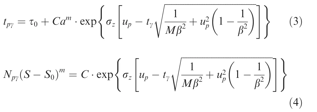
where τ0is the constant of material fitted from experimental data;Sis the peak stress in a random spectra loading history;Mis the size of sample;tis the statistical variable or number of stress cycles,or time;pis the reliability-level;upis the standard normal deviator related to the level of reliability;β is the correction coefficient of standard deviation;γ is the level of confidence;and σzis the standard deviation of sample.
From practice,it has been recognized that fatigue life is a logarithmic normal random variable correlated with the level of fatigue stress.If the level of fatigue stress is lower then fatigue life is of greater variability.In contrast,if the level of fatigue stress is higher then fatigue life is less variable.Therefore,the standard deviation σzcharacterising fatigue life is usually assumed to follow a following relationship.

wherecanddare the parameters to be determined from experiments.
Using Eqs.(4)and(5),it is possible to have the probabilisticS-Nfatigue properties pertaining to a level of reliability and a level of confidence as follows.11


whereSmis the mean nominal stress level.
It is worth pointing out that Yang and Chen12assumed crack propagation rate as a lognormal random variable process.This assumption needs to be validated,ideally from experimental data.
Infinite life implies that an artefact does not crack,or that pre-existing cracks no longer grow during an ultra-long life.This concept is apt for the steady cyclic loads with high cycles and low stress-levels.In this case,fatigue stress is less than the fatigue endurance limit,or stress intensity is less than the fracture threshold.Certain levels of reliability and confidence can be ascribed to this event.The two-dimensional probability distribution for fatigue endurance limit or fracture threshold derived from the constant-life diagram is one of the preconditions for infinite life design.Therefore,generalized constant life diagrams for fatigue and fracture properties were respectively proposed to be suited for all kinds of material:13

whereS-1is the fatigue endurance limit amplitude under symmetrical cyclic loading;ΔK-1is the fracture threshold under symmetrical cyclic loading;Kmthis the mean fracture threshold;KICis the fracture toughness.
Two-dimensional probability density functions(PDFs)for fatigue strength(Sa,Sm)and facture threshold(ΔKth,Kmth)were deduced from Eqs.(8)and(9)respectively as follows.14
2.3.Corrosion effect
Corrosion damage resulting from inter granular attack,exfoliation,pitting,etc.commonly causes crack initiation in metallic materials.Such a problem always appears on ageing fuselages and wings that encounter corrosion arising from environmental exposure.For example,pitting corrosion due to the electrochemical attack has been found on metal surfaces or within teardown airframes.Multiple-cracks often initiate at corrosion pits,substantially reducing fatigue lifetimes and residual strengths of ageing airframes owing to the inevitable interaction between adjacent multiple-cracks.Since more and more ageing aircrafts reach,and even exceed nominal design lifetimes,it is becoming crucial to understand the effect of corrosion on fatigue life during the design prediction stage of aircraft structures.It has been understood that corrosion environment has an evident adverse influence on the properties of pit nucleation and extension and pit-to-crack transition,and consequently the fatigue strength and the crack propagation resistance of metallic materials.Mechanical properties of metallic materials are unsusceptible to the corrosion on the surface of materials and dependent on the base material,
whereas fatigue properties of metallic materials are susceptible to the corrosion on the surface of materials.15,16This is because fatigue cracks more easily initiate and grow from corrosion pits on metal surfaces in a corrosive environment than in dry air.In reality,fatigue loading and corrosion are often simultaneously present,and the synergistic interaction between fatigue loading and corrosion has much more detrimental effects on crack initiation and propagation than each one alone appearing on its own.With the decreasing stress level,the corrosion effect increases,while the load-interaction effect decreases.5,17
Corrosion fatigue behavior for metallic materials or structural components pertaining to a specific calendar year oftby considering the effect of mean stress or stress ratio can be described as16

whereris the linear correlated coefficient;μ is the mean of population andσis the standard deviation of the population.
Figs.1(a)and(b)show the two-dimensional PDFs for fatigue and fracture strengths determined from experimental datasets for LY11CS A-alloy and 40CrNiMoA alloyed-steel.

where α0and β0are the material’constants determined by best fitting from experimental data sets;S0is the fatigue endurance limit for un-corroded metallic material;tis the calendar year,or corrosion time;R1is the specific stress ratio.
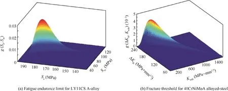
Fig.1 Two-dimensional PDFs.4
By using the model in Eq.(12)and the Palmgren-Miner rule,the calendar life under actual random loading spectrum can be evaluated expediently and easily.It is worth pointing out that in order to develop new theoretical model for depicting the corrosion effect on fatigue life,further work is needed to quantitatively determine microstructural sizes of material(including grains and grain slip boundary,dimple,short crack,etc.)in corrosive environments.
2.4.High/low temperature effect
Due to the superior high-temperature mechanical properties(e.g.,excellent strength and stiffness,superior fracture toughness,good resistance to corrosion,oxidation and creep,etc.),advanced metallic alloys(e.g.,titanium and aluminum alloys,Ni-based single-crystalline or polycrystalline super-alloys,alloy steels,etc.)are widely used in high performance aircraft and aero-engines as airframe component and gas turbine blade materials,where they are commonly encounter a wide range of temperature at high flight altitudes.For instance,some engine materials commonly sustain a wide range of high working temperatures(25 °C to 1000 °C),whereas some airframe materials such as Aluminum Alloys(AAs)often need to work in low operating temperature environments(-5 °C to-60 °C)at high flight altitudes.The high/low temperature has a significant influence on material properties,fatigue and fracture behaviors and damage mechanisms.High temperature often has an adverse effect on fatigue crack initiation and propagation behaviors for some metallic materials.This contributes to the fatigue mechanism transition from brittle cleavage fracture at lower temperatures to ductile quasi-cleavage fracture at higher temperatures,and the plasticity induced and oxide induced crack closure mechanisms.Multiple fatigue cracks usually occur from the oxidation sites in a local intergranular fracture mode at elevated temperature.Synergistic interaction between fatigue,creep and oxidation under thermomechanical stresses then causes the reduction of fatigue strength and crack propagation resistance.2,3In general,fatigue strength and crack propagation resistance for some aluminum alloys are affected by high temperature,but those for some titanium alloys are unaffected.The initiation and propagation of substantial secondary cracks is the primary reason for a slight influence of high temperature on the crack growth behavior of Ti-6Al-4V/ELI.In other words,the initiation and propagation for substantial secondary cracks on fracture surfaces of titanium alloys at high temperature can dissipate the energy to drive crack growth,thus releasing stress concentration localized at a crack front,thereby considerably decreasing fatigue crack growth.18
Low temperature has a notable and beneficial effect on fatigue crack initiation and propagation behaviors.It is well known that cyclic plastic deformation is a fatigue-driven force,mainly conditioned by the nucleation and motion of dislocations.However,dislocation activity is inherently controlled by the twinning and slip nucleation and growth.At low temperature,twinning frequently appears in the metallic alloys to produce more individual plastic deformation than slip,and it becomes the predominant plastic deformation mode.This causes the decrease of dislocation structures and the increase of ductility of alloy together with the release of stress concentration localized at the micro crack(or defect and flaw)tip,ultimately increasing fatigue life.Moreover,fatigue damage at the crack tip is strongly affected by the hydrogenembrittlement process.Low temperature generally retards the hydrogen-embrittlement process to enhance fatigue resistance of some metallic materials.4,19
In order to develop microstructural theoretical models for depicting the load-temperature interaction,further work is necessary.The focus would be to quantitatively determine microstructural sizes of material(including grains and grain slip boundary,dimple,short crack,etc.)in the case of known loading and temperature patterns.Then,it would be possible to establish the theoretical relationship model between the microstructural sizes of material and loading and temperature to quantitatively evaluate the load-temperature interaction.
2.5.Composites fatigue behaviors
Although static strength of composites is largely dominated by fibre strength,it is difficult to define static damage and failure in a simple way due to the random nature of fibre breakage and the role of the fibre/matrix interface.It has been argued that there is possibly a critical cluster of fibre breaks adjacent to one another that lead to catastrophic fracture of compos-ites.The formation of such critical clusters depends on the statistical distribution of fibre strengths and the local stress transfer in the vicinity of fibre breakage which,in turn,is affected by the fibre/matrix interface.The compression strength of composites though cannot be a true metric for the fibre strength though this can be a measure of the integrity of the fibre/matrix interface and the capability of a matrix to support the fibre against buckling.
Like compression strength,fatigue strength depends more on the matrix and interfacial characteristics than on fibre strength.On a microscopic level,fatigue failure of composite laminatesis shown to cover four stages as follows20:(A)multiple matrix cracking takes place along fibres in off-axis plies,culminating in a saturation cracking state in individual plies;(B)locally linking-up occurs between ply cracks by the debonding on the ply/ply interface;(C)growth and coalescence of delamination takes place;(D) fibre breakage in the longitudinal plies,and over-all failure occurs finally.The above damage process depends on constituent material properties and lay-up.It has been shown21that under tension-tension cyclic loading,fatigue damage mechanisms for notched composite laminates are similar,whereas fatigue properties change with the lay-up of a composite laminate.The release of stress concentration resulting from fatigue damage causes an improvement in residual strength for notched composite laminates as against their static strength.Fatigue damage mechanisms of notched composite laminates are more complicated under compression-compression cyclic loading than under tension-tension cyclic loading.These depend on the lay-up and dimensions of the composite laminate,notch size and clamping fixture,etc.The residual strength in such cases is much lower than the static strength.
Fatigue behavior of composites is associated with stress ratio.Fatigue damage always appears around the notch in notched composite laminates under cyclic loading(below the static strength).The damage at the notch initially can effectively cause a reduction of stress concentration related with the discontinuity.This,in turn,leads to an improvement in the residual strength,especially under tension-tension cyclic loading.Under tension-compression cyclic loading,delaminations can occur and grow between the lay-ups of notched laminate,leading to greater instability of load-carrying 0°plies.
Static and fatigue strengths are also understood to be related with temperature.Static tensile strengths at room and low temperatures are close.However,static compressive strength at high temperature is significantly lower than that at room temperature.The resin matrix loses more stiffness with increasing temperature;so static compressive strength of composites drops.Static tensile strength for notched composite laminate is only about half of that for an unnotched laminate.Composite laminates with different notch sizes and different widths at different temperatures have quite close tensile strengths to one another.The residual strengths of notched composite laminates after 106cycles are also close,and all residual strengths under tensile-tensile cyclic loading are greater than their static tensile strength.One primary reason for this is that the release in stress concentration resulting from fatigue damage induces an improvement in residual strength of notched composite laminate.22
Due to the variety of fatigue damage,it is hard to define fatigue damage in composites in a unique manner.Therefore,the definition on fatigue damage is a function of the number of stress cycles and material’characteristic variables involving strength and stiffness degradations,crack size and density,etc.The more promising damage criteria have been proved to be some functions with regard to material’s physical characteristic variables.Some criteria are linked to the residual strength,while others address the problem of residual stiffness or strain.All damage metrics have their disadvantages and advantages;each of these,nevertheless,is always apt for one particular composite system.The origins of damage modelling trend were linear.However,non-linear quadratic damage criteria have been proposed to account for the inherent complexity in composites.All damage models are empirical and phenomenological,derived from experimental data-sets obtained from static and fatigue tests.The empirical degradation models with regard to residual strength23and stiffness(or strain)22,24are respectively

wherenis the number of cyclic stress cycles;bis the material’s constant;sis the cyclic stress-level;R(n)and ε(n)are respectively the residual strength and the fatigue strain pertaining to fatigue stress cyclesn;R0is the initial ultimate strength;andE0is the initial elastic modulus.
Eqs.(13)and(14)are surfaces for describing the relationship between the number of cyclic stress cycles and the residual strength(or residual strain ε(n)).However,owing to the stochastic and random nature of fatigue life and damage,appropriate random analysis has to be carried out on Eqs.(13)and(14)by taking into account the influences of stochastic factors.The probability distribution functions of residual strength and fatigue life could then be shown to be23
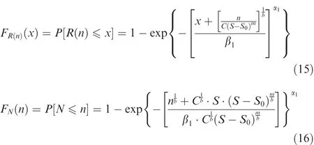
where α1and β1are the shape and characteristic parameters for Weibull distribution with two parameters for ultimate strength.
Eqs.(15)and(16)show that residual strength and fatigue life follow the three-parameter Weibull distribution.Note that a major drawback for the models based on such statistical strength/stiffness degradation characterization is their relative weak relevance to damage mechanisms in composites.As a result,a model based on damage mechanics concept has been devised as25

whereDiis the damage variable;Eiandare the initial and damaged elastic moduli respectively;andGiandare the initial and damaged shear moduli,with,
For damaged anisotropic composites,the local stress tensor can be depicted through the effective stress tensor in the nominal stress tensor form as

where σ is the nominal stress tensor;σ~is the effective stress tensor;and M( D)is the fourth-order damaged transformation tensor with 21 independent parameters.In case where the principal axis of stress coincides with the damage evolution direction,M( D)becomes

whereSijis the compliance tensor;δikis the Kronecker function.
In light of the strain energy reciprocal theorem,it can be shown that the damaged complementary energy pertaining to the nominal stress tensor equals the undamaged complementary energy pertinent to the effective stress tensor.

where S is the fourth-order compliance tensor with 21 independent parameters.In case where the principal axis of the material coincides with the direction of coordinate axis for orthotropic composites,there S has only 9 independent parameters.
The concept of damaged strain energy release rate is interpreted as the fatigue-driven force for damage evolution;this is analogous to energy release rate(or the J-integral)in fracture mechanics.Three-dimensional damage evolution is written as25

where ΔΓiis the damaged strain energy release rate variable;ΔW( σ,D)is the damaged complementary energy tensor;qiis the material’s constant.
Integrating the above equations,it is possible to obtain the σa-N-Rsurfaces which describe the relationship between fatigue lifeN,stress amplitude σaand stress ratioRin a three-dimensional coordinate system.
The model based on damage mechanics seems good,though it does not imply the model is perfect.In order to identify and isolate the complex fatigue damage modes in composites,the damage transition stress pertinent to fatigue damage characteristics needs to be better defined.This points to the need for a re-examination of the fundamental physics underpinning damage to composites subjected to fatigue loading.
2.6.Composite fracture behaviors
Initial defects/ flaws might occur in processing and assembling stages.These propagate under cyclic loading and could,ultimately,cause catastrophic failure of a composite structure.It has been demonstrated that notch sensitivity on the residual strength and fracture behavior of composites is dependent on various factors such as mechanical properties of fibre and matrix, fibre volume fraction and bundle size,ply orientation and stacking sequence,geometry and dimensions,notch shape and size,stress level,etc.Tensile experimental results showed that26a decrease occurred in tensile residual strength for notched PWF(Plain Weave Fabric) Kevlar/TPU (Thermoplastic Poly Urethane)envelope ranging from about 4%to 10%(and as shown in Figs.2(b)and(c))as compared with those for unnotched ones(as shown in Fig.2(a)).Alternatively,tensile residual strengths for notched envelopes with the hole diameters of 8 mm and 6 mm respectively were 10%and 4%lower than those for unnotched ones.This means that the notch sensitivity increased slightly with the increase in the hole size.The failure mode for a PWF Kevlar/TPU envelope subjected to a tensile load could be concluded as the TPU cracking,fibre/TPU debonding, fibre pullout and rupture,and catastrophic fracture.Note that tensile strength of the TPU is much lower than that of the Kevlar-fabric.Thus,TPU cracking first appears in the ultrathin envelope subjected to tension arising from severe strain gradients.Like a bridge between the two crack faces,the Kevlar fibre bundles ahead of main-crack-tip withstand the primary tensile load and retard further TPU cracking(or the effect of crack-front blunting).With an increase in tensile load,the occurrence of fibre-bundles rupture and further TPU cracking is followed by the fibre/TPU debonding and fibre-bundles pull out from the surrounding TPU,which is resisted by the friction on the fibre/TPU interface.Thus,notch sensitivity,stress concentration and tension residual strength in notched envelopes are predominantly dependent on the Kevlar-fabric(and not the TPU).
Tear resistance,the maximum nominal stress to tear a flexible material,depends on the properties of constituent material, geometry and dimensions of micro-structure,environment,loading,etc.Tear resistance is analogous with fracture resistance.As shown in Fig.3(a),for an infinite PWF Kevlar/TPU envelope containing a slit with a specific length along a specific angle away from the longitudinal direction,in a plane tensile stress state,the slit propagation is in a mixed mode I and II state.By means of a maximum hoop stress criterion,the tear resistance and angle for the notched PWF Kevlar/TPU envelope can be shown to be26

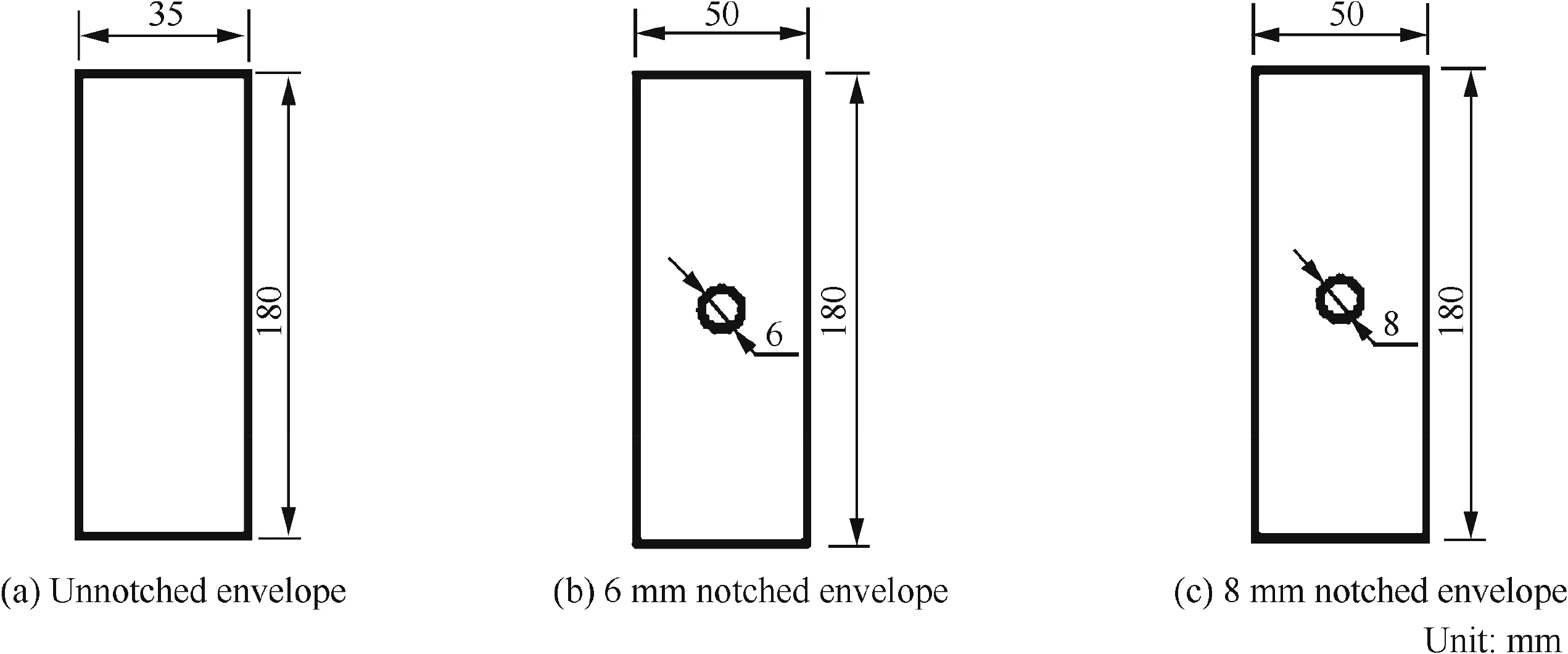
Fig.2 Geometry and dimensions of specimens.
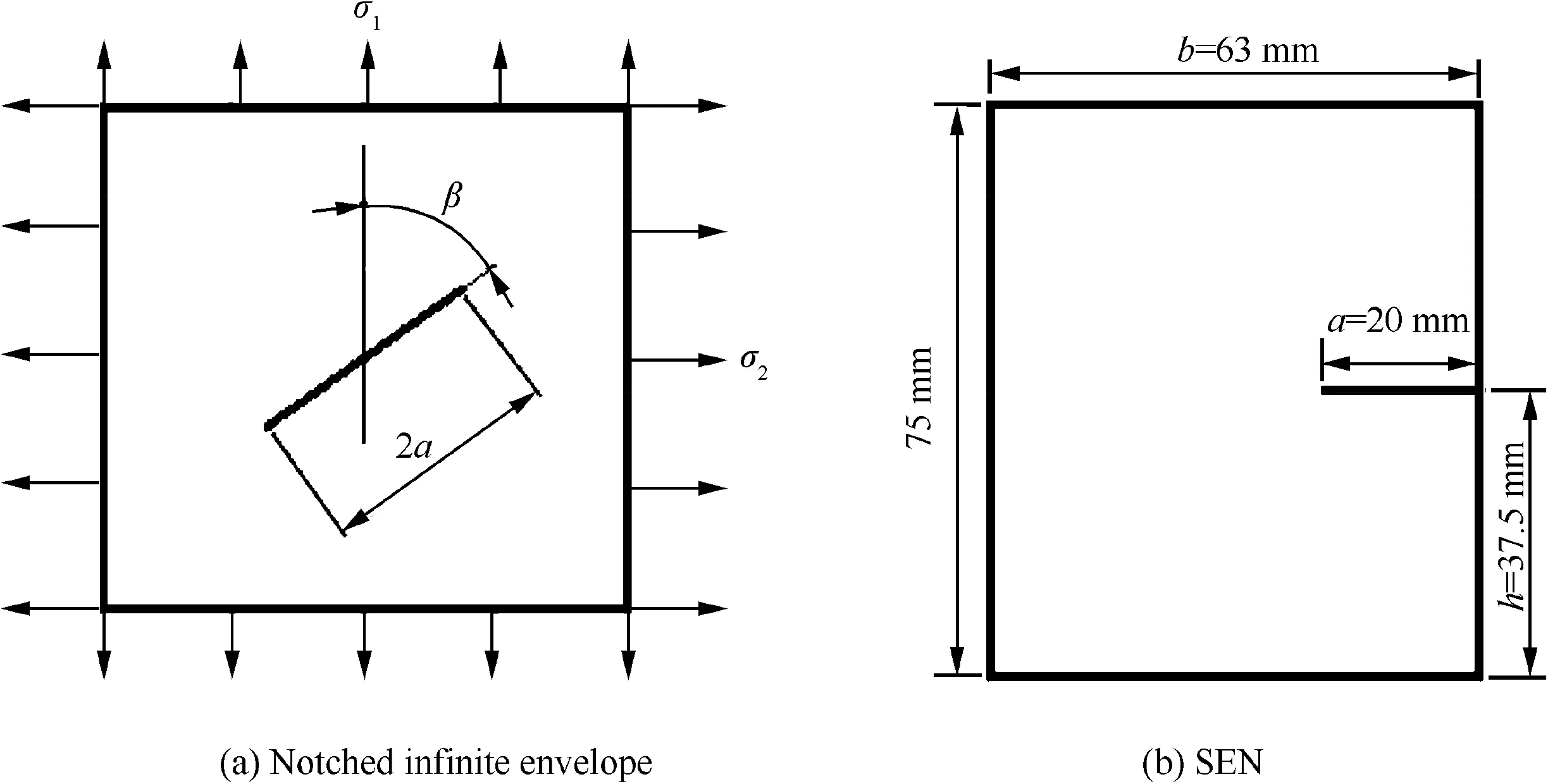
Fig.3 Geometry and dimensions of notched specimens.
where σCis the tear resistance;θ0is the tear angle away from the crack direction;α is the ratio of σ2to σ1or α = σ2/σ1,and σ1and σ2are respectively the longitudinal and transverse stresses.For Single-Edge-Notched-Tension(SENT)specimens(shown in Fig.3(b)),it is possible to have

whereaCis the critical crack size;σCis the critical stress;andY(a)is the calibration factor of stress intensity.
From Eqs.(22)-(24)and the experimental results,it can be shown that26the tear resistance for notched PWF Kevlar/TPU envelope with a 1 mm slit length is about half the tensile strength for an unnotched envelope.This implies that the tear resistance has significant notch sensitivity.Conversely,tensile strength is only slightly notch sensitivity for envelopes with a central circular hole.
In accordance with fracture mechanics theorems,Strain Energy Release Rate(SERR)was first applied to characterize mode I/II fracture toughness under static loading.In recent years,the SERR has been employed to depict crack propagation behavior of fibre/epoxy reinforced composites subjected to cyclic loading in mode I/II delamination.SERR for a 3-ENF beam(shown in Fig.4)can be expressed as follows27

whereGIIis the SERR in mode II delamination;LandWare the half span and width of 3-ENF specimen,respectively;andPand δ are the applied load and displacement for mode II interlaminar delamination,respectively.
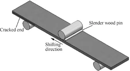
Fig.4 3-ENF beam.
The concept of SERR is interpreted as the fatigue-driven force for mode II interlaminar delamination propagation.By using Eq.(25),the normalized SERR becomes

whereGII,maxis the maximum SERR for mode II delamination;aCandPCare the critical crack size and applied static load respectively;PmaxandPaare separately the maximum value and amplitude of applied cyclic load.
Eq.(26)shows the pattern of fatigue-driven force from static fracture properties.Obviously,under constant-amplitude cyclic loading at a fixed stress ratio,the fatigue-driven force increases monotonically with the increase in delamination length.
Similarly,analogous to the Paris-Erdogan model in fracture mechanics,delamination growth rate da/dNversus ΔGII,i.e.for mode II,can be shown to be27

where ΔGIIis the strain energy release rate range; δmaxis the maximum displacement for mode II delamination.
Integrating Eq.(27)leads to the mode II delamination crack size,namely,

whereEandhare the longitudinal modulus and half thickness of 3-ENF specimen,respectively;anda0is the initial crack size.
Eq.(28)is called as the fatigue-driven model for describing the law of the mode II delamination propagation size versus the number of cyclic loads.
3.Fatigue load spectra
Fatigue reliability assessment requires identification of the fatigue strength distribution function related to a material’s fatigue properties,the scatter in the loading spectra and the PDF of load cycles.The latter are extracted from short time(measured or simulated)random load spectra historical records based on a rain- flow counting procedure.However,a random load spectrum history in such a case is similar to a divergence-convergence-wave(shown in Fig.5(a))that would have remained,with some load cycles in this load history not being able to be extracted by using classical rain- flow counting procedures because the hysteresis loops of these load cycles are not closed.28Consequently,a modified counting procedure has been presented for extracting these load cycles.28Alternatively,the load history like divergence-convergence wave is first separated into two segments at the lowest valleyNminor at the highest peakNmax(shown in Fig.5(a)).A load history like convergence-divergence wave is then obtained by linking the first and last points(shown in Fig.5(b)).Again,using the classical rain- flow counting procedure,the remaining load cycles are extracted from the load history like convergence divergence wave.As a consequence,for four adjacent peak and valley pointsj=i-1,i,i+1,i+2 on the load history like convergence-divergence wave,it is possible to have the following relations:

By this way,all the load cycles are defined by using a pair of reversal stress values (Si,Si+1)on the load history like divergence-convergence wave.The extracted load cycle from the load history like convergence-divergence wave then becomes28

In general,at least three or four p.d.f.s have to be implemented for the distribution hypothesis testing to obtain the apt p.d.f description for all extracted load cycles from a random spectra load history.It has been shown that load amplitudeSaand mean loadSmseem to follow the semi-Gauss and Gauss distributions respectively.28Thus,the two dimensional combined p.d.f.of load cycles(shown in Fig.6)becomes

where μ1and μ2are the population means of the Semi-Gauss and Gauss distributions respectively;ands1ands2are separately the population standard deviation of the semi-Gauss and Gauss distributions.
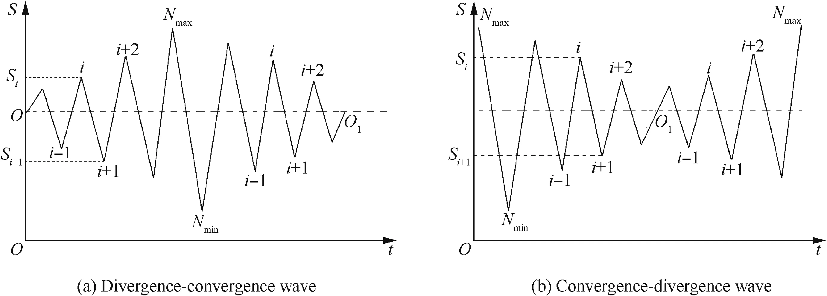
Fig.5 Load history.28
In practice,full-scale accelerated fatigue tests are often employed to assess structural fatigue life under accelerated random spectra load history.A number of procedures such as the FALSTAFF,TWIST,WASH I standard spectra,etc.have been devised to generate accelerated random spectra load history.However,the problem is that none of the aforementioned procedures by themselves fulfil all the requirements because:(A)the information about the sequences of extracted load cycles from actual random spectra load history should be maintained in new generated random spectra load history;(B)the damage in any accelerated load history should be the same as that in the actual load history;and(C)the accelerated load history should be of shorter length than the actual load history in order to reduce the test time.As a result,a modified procedure has been developed to generate new generated random spectra load history for full-scale tests,by removing the small load cycles,because they contribute negligibly small fatigue damage,and by merging the other load cycles to induce a slight damage.29In other words,all extracted load cycles from rain- flow counting procedure are first identified as the primary load cycles,or the small load cycles,or the secondary load cycles.After this,the primary load cycles are maintained in the new load history.And the small load cycles are removed and the remainder load history then replaces the original load history(show in Fig.7).Moreover,two sequential and adjacent secondary load cycles are merged into a new secondary load cycle by using the equivalent damage calculation,and the new load history is then instead of the original load history(show in Fig.8).Finally,new accelerated load history is generated.
With increasing statistical data of actual flight loads for a similar type of airplane,it becomes more and more important to generate an apt flight spectrum and random ground-air ground load spectrum based on random sequencing methods.30
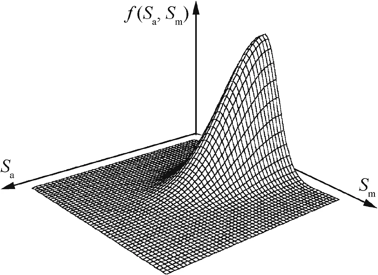
Fig.6 Combined PDF surface for fatigue stress.28
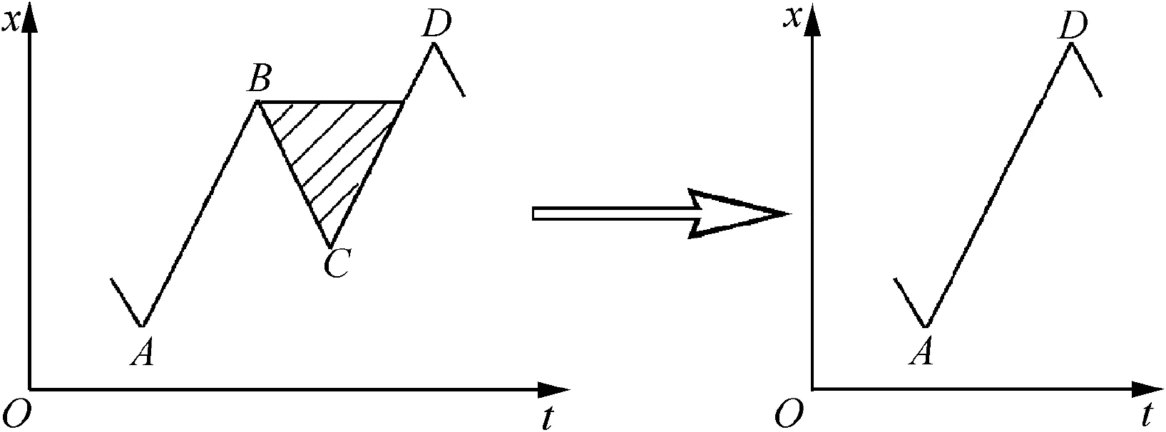
Fig.7 Deleting small load cycle.
4.Fatigue and fracture lifetimes
4.1.Fatigue life of mechanical artefacts
Mechanically fastened joints such as bolted or riveted double lap and single overlap joints,etc.are commonly found in aero-structures.Fatigue characteristics of mechanically fastened joints depend on numerous factors such as mechanical properties of material,geometry and dimensions of fastener and joint,processing and assembly condition,load state and environment,etc.Superficially,it would appear that there should be a large number of correction parameters/curves to consider in allowing for the aforementioned effects in fatigue assessment for mechanically fastened joints.In reality,it is a formidable and infeasible task to conduct such comprehensive evaluations.Therefore,two new fatigue characteristics approaches,one for similar structural detail31and the other for full-scale structure,32have been developed taking account of the paucity of experimental data.
For a representative multi-fastener single-overlap joint subjected to plane stress and as shown in Fig.9,the nominal stress scaled with the superposition of normal extrusion/transfer and bypass stresses around the fastener hole atith row andjth column is argued to be considered as fatigue-driven force.31

wheren1andn2respectively are the number of fastener rows and columns,and usually are odd;Wijis the width of oblique sectionA-Aon right separated down-sheet through the fastener hole atith row andjth column;Wn1n2is the width of oblique sectionA-Aon right separated down-sheet through the fastener hole atn1row andn2column;Mijis the number of fasteners on oblique sectionA-Aon right separated down-sheet;represents the total number of fastener holes on the right separated down-sheet;d1is the diameter for fastener hole;and σmainis the first principal stress in plane stress state.
From Eq.(34),the most severe nominal stress in plane stress and uniaxial stress states respectively can be shown to be


Fig.8 Merging two sequential and adjacent secondary load cycles.
wheredis the pitch between adjacent fastener holes and σxrepresents the stress in the direction ofx-axis.Eq.(35)is for the fastener hole at the first row and the first column in plane stress state,while Eq.(36)is for the first row of fastener hole in uniaxial stress state.
Fatigue life is mostly dependent on the nominal stress level around representative similar structural details on multifastener mechanical joint.Consequently,from the Palmgren-Miner rule and theS-Nfatigue characteristic of representative structural details,incorporating geometry and dimensions of multi-fastener mechanical joint,mechanical properties of material,actual load spectra and boundary conditions,the nominal stress and fatigue life around similar structural details can be evaluated in a systematic,minimalist manner.Note that the nominal stressSin theS-Nfatigue characteristic of representative similar structural details should be determined from Eq.(36).
For complex mechanical artefacts with different structural parts made from different materials(such as the hydraulic actuator in Fig.10),it is hard to accurately predict local(even nominal)stress/strain fields around structural details.Thus also it is a difficult task to evaluate fatigue life.Therefore,from the relationship between nominal stress and load on artefacts,the nominal load is argued to be scaled as the fatigue-driven force.Again,fatigue life can be evaluated under assumed loading conditions in a systematic,minimalist manner.32
From the above nominal load concept,empirical power function with three-parameter of fatigue characteristic of hydraulic actuator(shown in Fig.10)can be written as32

whereP∞is the structural fatigue endurance limit;Ais the section area of piston rod;Pais the amplitude value of nominal force on the piston rod;andPmis the mean value of nominal force on the piston rod.
Eq.(37)displays aPa—Pm—Nstructural fatigue characteristic surface of hydraulic actuator in a three-dimensional coordinate system.Using Eq.(37)and the Palmgren-Miner rule,structural fatigue endurance limitsS∞can be deduced from experimental datasets in full-scale step constant amplitude loading tests of hydraulic actuator.32

wherePai,Pmiandnirespectively denote the amplitude,mean and number of nominal load cycles at theith level in full-scale step constant amplitude loading tests.
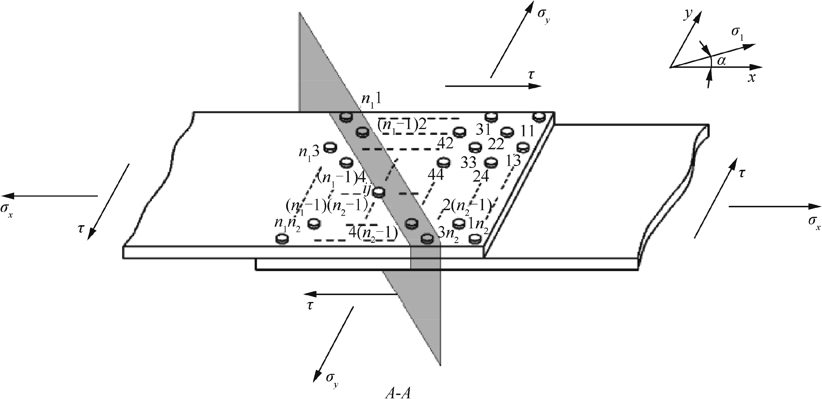
Fig.9 Idealized multi-fastener single-overlap-joint subjected to plane stress.
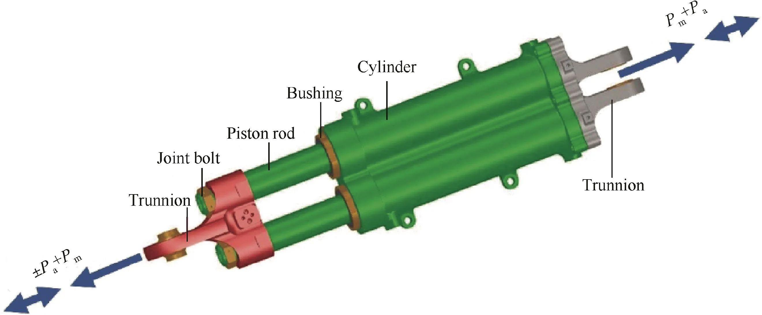
Fig.10 Hydraulic actuator diagram.
From Eq.(38),it is apparent that only structural fatigue endurance limit is unknown,and so it can be determined through numerical solution procedures.In addition,only one full-scale artefact needs to be provided for fatigue tests in order to determine structural fatigue characteristic of complicated mechanically artefacts.
4.2.Load interaction
In order to evaluate fatigue lifetime under random spectrum loading,some accumulation damage rules,such as the Palmgren-Miner and modified Miner models,etc.,have been proposed in the literature.The Palmgren-Miner model(i.e.,linear cumulative damage rule)is simple and,usually in many cases,effective in fatigue life prediction.A modified Miner model necessitates a number of experimental data sets to determine the accumulation damage variable,although the prediction precision is better than the Palmgren-Miner model.The Manson model(i.e.,double-linear cumulative damage rule)and the Miller model(or non-linear cumulative damage rule)are valid for predicting the lives of fatigue crack initiation and propagation.However,one drawback of these models is the difficulty and complexity to divide fatigue crack initiation and propagation.As a result,the Palmgren-Miner model is commonly used to evaluate fatigue lifetime.
It has been proved that the load interaction significantly affects fatigue life for random spectrum loading,due to the effects of tensile-overload-retardation and compression acceleration. The latter, overload-retardation-reduction,results from compression following the tensile-overload.However,it has been well understood that one drawback of aforementioned accumulation damage rules is their neglect of the load interaction in fatigue life prediction under random spectrum loading.In reality,some models(e.g.,the Wheeler,Willenborg,Elber,Newman and Willenborg-Chang models,etc.)have been devised for modelling the load interaction in residual life(or crack growth life)prediction.The Willenborg-Chang model,for instance,based on plastic zone theory,has been proved to be successful for modelling the load interaction on crack growth life(or residual life)under random spectrum loading.Nevertheless,to the best of our knowledge,these models considering the load interaction have been employed only for residual life prediction and never for fatigue life evaluation for random spectrum loading.The problem is that none of the aforementioned models accounting for the load interaction alone fulfils fatigue life prediction under random spectrum loading.Furthermore,the accumulation damage rule considering the load interaction in fatigue life prediction is scarcely reported.For this reason,a modified accumulation damage rule has been developed incorporating the Palmgren-Miner rule and the Willenborg-Chang model to take the load interaction into account in fatigue life prediction for random spectrum loading.4Actually,cyclic plastic deformation is a fatigue-driven force;the load interaction effect on fatigue damage fundamentally depends on the overload plastic zone.The concept of effective stress ratioReffin the Willenborg-Chang model has been utilized to consider the load interaction effect.This has been proved to be apt and effective in depicting the local stress ratio at crack tip within the overload plastic zone during cyclic loading.Consequently,analogous to the Willenborg-Chang model,the concept of effective stress ratioReffis introduced in the Palmgren-Miner rule to depict the local stress ratio at the micro-crack tip within the overload plastic zone during cyclic loading.This is argued to account for the load interaction on fatigue damage in fatigue life prediction.4
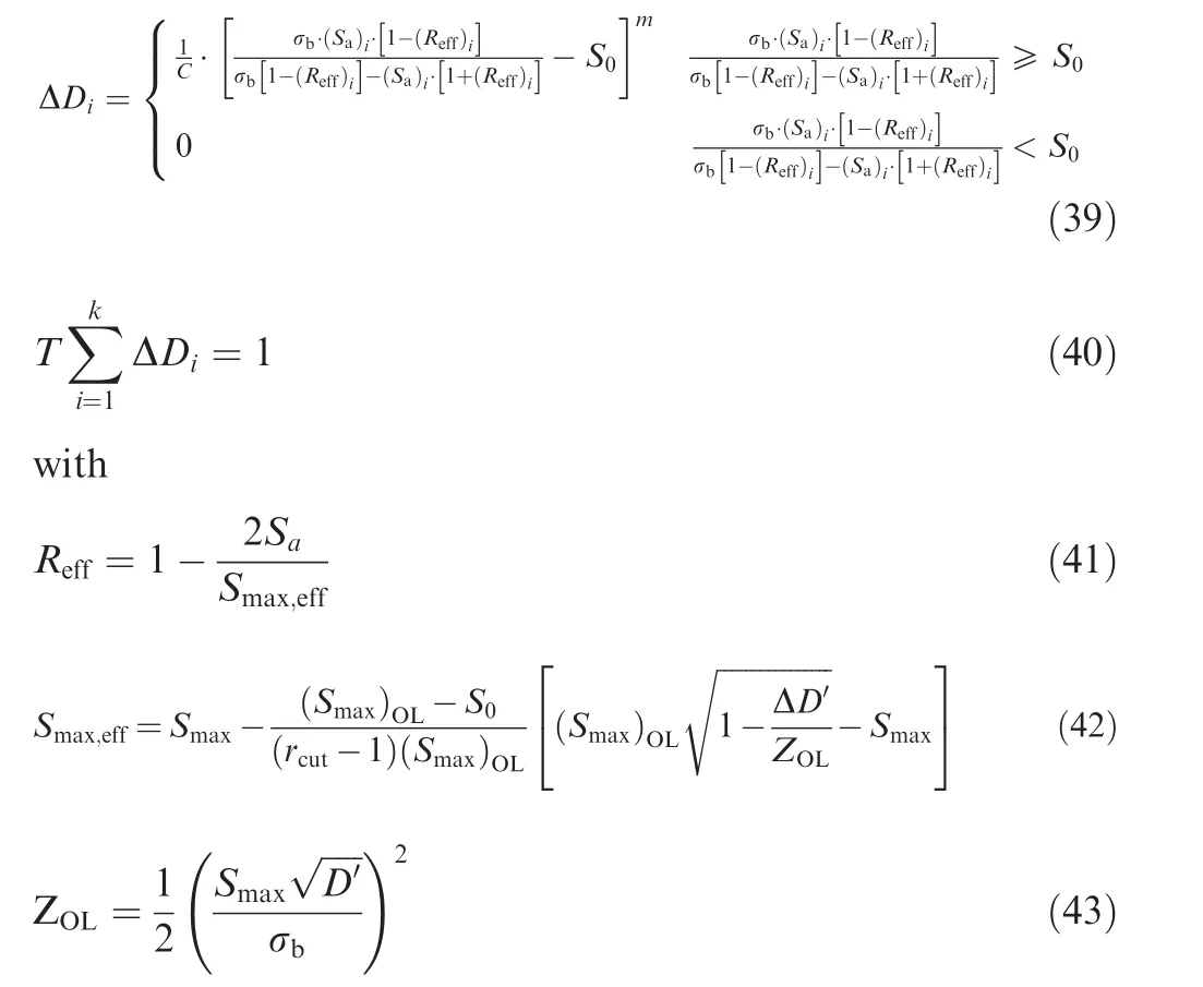
whereTis the block number of random spectrum load histories to fatigue failure;Drepresents the fatigue damage;ΔDiis the fatigue damage increment pertaining to theith stress cycle in random spectrum load history;kis the number of stress cycles in random spectrum load history;Reffis the effective stress ratio,or the local stress ratio at micro-crack tip within the overload plastic zone;Smax,effis the effective maximum nominal stress,or the local maximum nominal stress at micro-crack tip within the overload plastic zone; (Smax)OLis the overload maximum nominal stress;rcutis the overload shut-off ratio;ΔD′is the fatigue damage increment through the overload plastic zone;andZOLis the size of overload plastic zone.
From Eqs.(39)-(43)and material properties,together with actual random spectrum load history,fatigue life can be modeled through such cycle-by-cycle accumulation calculation.Importantly,the parameters and fatigue accumulative damage(or fatigue life)in this model can be expediently and easily determined.
In the same way and using Eq.(2),a slight modification to the Willenborg-Chang model can be established to account for the effects of fracture threshold,load interaction and stress ratio.5
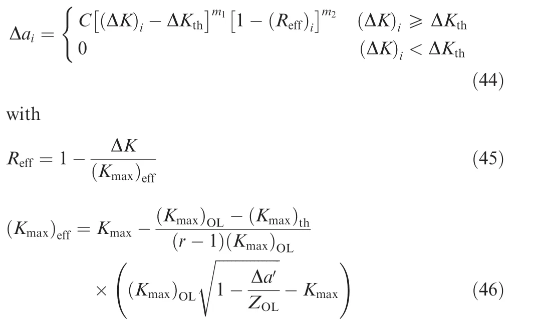

where(Kmax)effdenotes the effective spectrum peak stress intensity;(Kmax)threpresents the spectrum peak fracture threshold;(Kmax)OLdenotes the spectra peak stress intensity corresponding to overload stress cycles;Δa′denotes the crack growth increment following the overload.
Eqs.(44)-(48)can be used to model residual life under actual random spectrum load history.
5.Reliability-based service period
In general,through full-scale fatigue tests or theoretical prediction,the modelling result represents the median value of fatigue life for an engineering artefact,with the reliability level of 50%.Actually,fatigue life data is characterised by large scatter.Consequently,from a viewpoint of engineering,the scatter factor is introduced to consider fatigue damage randomness in safe fatigue life assessment.33
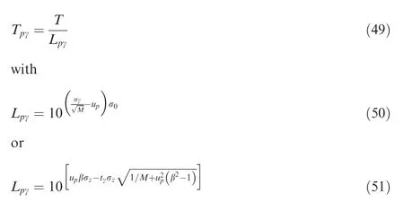
whereLpγandTpγare the scatter factor and safe life pertinent to a level of reliability and a level of confidence;σ0is the standard deviation of logarithmic fatigue life population,and usually ranges from 0.16 to 0.2;uγis the standard normal deviator pertaining to a level of confidence;tγis thet-distribution percentile corresponding to a level of confidence.
Eq.(50)is applied only for known standard deviation of population,while Eq.(51)is adopted only for unknown standard deviation of population.Since the fatigue process comprises of crack initiation and propagation,structural life assessment necessitates both safe life and damage tolerance approaches.Safe life approach is used to assess structural life,while damage tolerance method is implemented for ensuring operational safety.Accordingly,a reliability-based model has been devised for structural life assessment based on the concept of probable lifetimes at crack initiation and crack propagation to critical size.34For an engineering artefact comprising a system withi=1,2,...,mseries elements or components,the component reliability is given as.34

wherepiandp*irepresent the reliability levels for possible crack initiation and propagation of theith component,respectively;p0is the detection probability of crack;andRiis the reliability level for theith component.
The levels of reliabilitypandp*pertinent to the lives of crack initiation and propagation ofTandT*should be respectively obtained from Eq.(50)or Eq.(51)and the median lives of crack initiation and propagation from a small number of experimental data or theoretical prediction.Thus Eq.(52)can be written as

wherefi(Ti)andare the reliability levels for possible crack initiation and propagation of theith component,respectively.
It is worth noticing that Eq.(53)has described the possible events of the detection of the initial crack,and the crack initiation and propagation.However,it has not accounted for the events of more than one inspection and repair(in a temporal format or for different components)yet.Even so,Eq.(53)can still effectively and realistically evaluate the first inspection and maintenance period for a new and first used engineering artefact,in an easy way.When the first inspection and maintenance have been fulfilled,using the analogy of Eq.(53),a new reliability-based model should be established to determine the next inspection and maintenance period for the repaired artefact.
In case that the artefact is first used or new,and no crack is visibly detected(orp0=1),from the condition ofT=T*and Eq.(53),the first inspection and maintenance periodT1is

Notably,Eqs.(53)and(54)are suited only for assessing the first inspection and maintenance period for a first used and new artefact.Further,future work should focus on the consideration on the events and effects of more than one inspections and repairs (in a temporal format or for different components).
6.Adhesively bonded composite patch repair
Adhesively bonded composite patch repair is increasingly being applied for corroded or cracked metallic substrate because of the advantages over traditional mechanical repair.Experiments35have shown that adhesively bonded composite patch repair could improve static and fatigue strengths of repaired panel.Static and fatigue strengths of a repaired panel are significantly sensitive to the thickness of composite patch.A proper thickness could ultimately increase static and fatigue strengths,while an inappropriate thickness could induce only slight benefits,perhaps even adverse effects.The surfacenotched substrates of AA LY12CS adhesively repaired with three kinds of fibre/epoxy bonded composite patches of T300/3234,G803/3242 and SW220/2322 with the same thickness yielded the close static strength to the parent,virgin base structure,but different fatigue strengths.There was a slight difference in failure modes for surface-notched substrates with and without adhesively bonded composite patch repair under static tensile loading.With increasing tensile load,local buckling took place around the notch on the repaired substrate,which was followed by debonding of the interface between composite patch and notch.After this,the crack initiated at the notch front and quickly propagated.Thereafter,the interlaminar delamination appeared on the composite patch and the crack penetrated the aluminum-alloy substrate until final rupture.It is interesting to notice that no debonding between the substrate and bonded patches occurred until final failure.
It is essential to fully understand the effects of important parameters such as patch thickness,layer angles and patch material,etc.on the mechanical behavior of repaired panel.Therefore,a three-layer FE model(shown in Fig.11)and a progressive damage algorithm based on the birth-death element and the Tsai-Wu criterion have been presented to identify the failure modes,to model the failure mechanism and to understand the aforementioned effects.36The simulations revealed that an appropriate elastic modulus and thickness of adhesive layer could strongly improve static strength of the repaired panel.Similarly,a proper thickness,elastic modulus and length-width ratio of bonded composite patch could significantly increase static strength.The simulation efforts were consistent with the findings from tests.
7.Plain woven fabric composites and composite artefact
7.1.PWF composites
With the wide application of PWF composites,their mechanical properties and failure mechanism have been comprehensively investigated.A series of analytical models have been proposed to predict mechanical properties and strengths of PWF composites,including tensile,37compression,38in-plane shear39and biaxial tensile moduli40and residual thermal stress41of plain orthogonal weave fabric composites,and tensile and in-plane shear moduli42and strengths43of Triaxial Weave Fabric(TWF)composites,etc.Biaxial and triaxial yarns in a micromechanical Unit Cell(UC)(shown in Figs.12(a)and(b))are idealized as curved beams with a path expressed as sinusoidal functions.The mechanical properties and strengths of PWF composites are deduced using the principle of minimum complementary energy and with appropriate geometrical assumptions and approximation.The predictions from the new models agree well with experiments.Since the crimp,or undulation,of the yarns significantly affects the mechanical properties and strengths,it is desirable to optimize the microstructures of PWF composites to obtain the optimal mechanical properties and strengths in future.
7.2.Composite joints
Hybrid RTM-made composite joints(such as T-joint,I-joint,Π-joint and cross joint,etc.)are receiving wide application in structures(shown in Fig.13).Joints in composite structures are the weak links in structures.In some worst cases,their failures can cause global failures of structures.Moreover,a large number of factors such as mechanical properties of fibre and matrix, fibre volume fraction and bundle size,ply orientation and stacking sequence,processing condition,geometry and dimensions,loading condition and environment,etc.have an influence on static and fatigue strengths and failure mechanisms of hybrid RTM-made composite joints.Static strengths and failure mechanisms were systematically determined through static tensile tests of cross joints,44pull and push bending tests of T-joints,45three-point flexure tests of I-joints,46and four-point flexure tests of Π-joints.47Static failure mode for composite joints usually starts with a debonding initiation and propagation along the triangular zone boundary until completely separation and breakage occurs between adjacent skins.A progressive damage model incorporating mixed failure criteria and birth-death elements have been deduced to identify the failure modes,to model the failure mechanism and to predict initial and ultimate loads.Prediction results correlate well with experiments.
7.3.High-altitude balloon
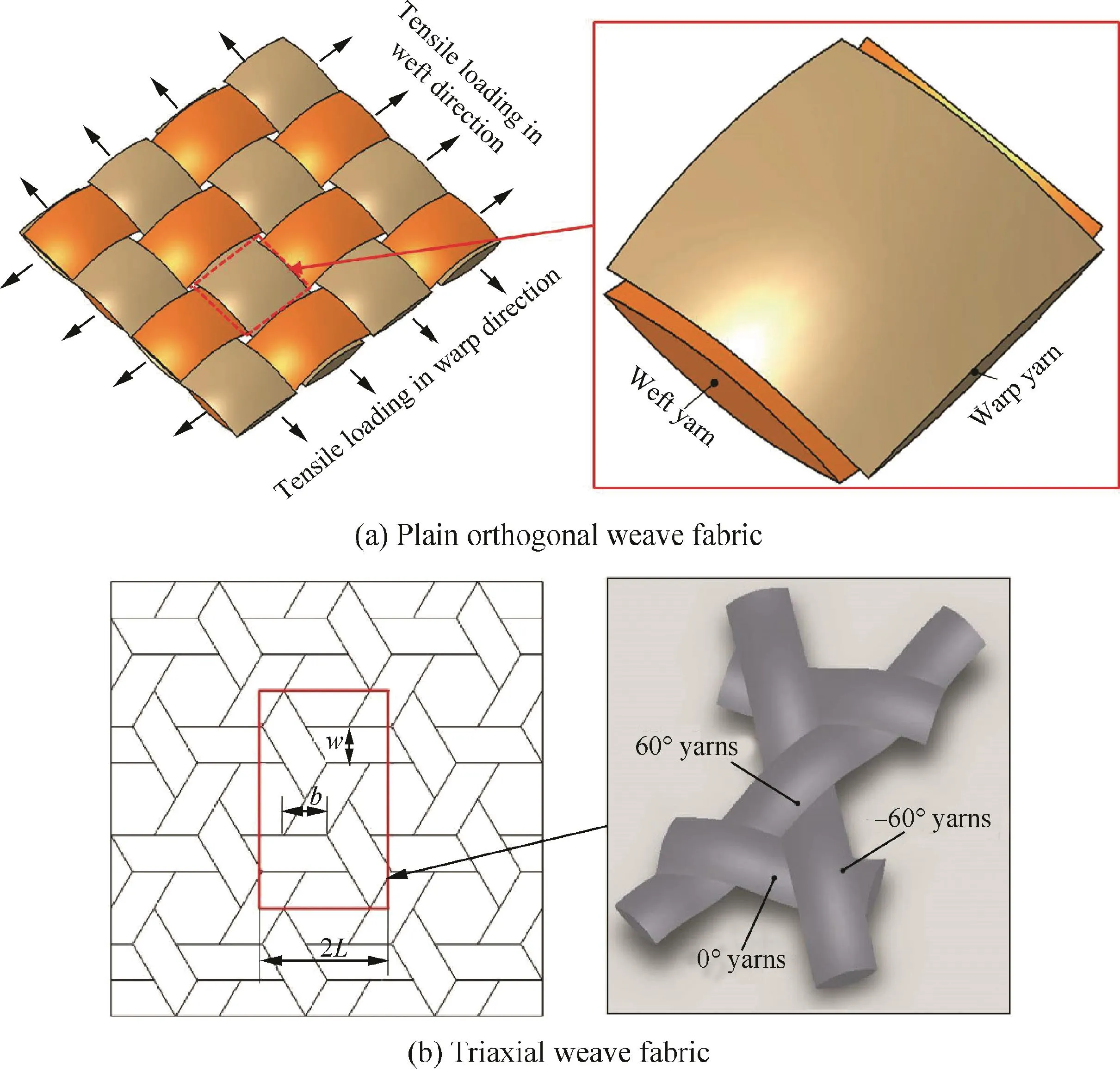
Fig.12 Representative unit cell of PWF composites.

Fig.13 RTM-made composite joints.
Modern large scientific high-altitude balloons subjected to a payload have the axisymmetric tear-drop-like natural geometric shapes.Meanwhile,their envelopes usually collapse and the top portions of the balloons often become smaller and more concentrated(shown in Figs.14(a)and(b)).Actually,like the standard membranes,the envelopes are under biaxial tension(shown in Fig.14(c)).The tensions are predominantly in the meridional direction,but negligibly small in the circumferential direction.Nevertheless,the circumferential tension is not necessarily zero for balancing against the pressure of lifting gas.However,it cannot resist the compressive loads arising from the payloads to result in a reduction in the circumferential radius,and ultimately causing the circumferential fine folds and wrinkling of excessenvelope material(shown in Fig.14(a)).Therefore,the meridional lengths of the balloon become greater;the circumferential radii are less with a payload as compared against without a payload.As shown in Fig.14(d),the outer broken,inner solid and broken curves illustrate the actual and idealized envelope boundary shape on the horizontal cross-section of balloon without and with a payload respectively.The axisymmetric tear-drop-like natural geometric shapes for the high-altitude balloons with a payload can be generally considered as the rotators of axial-symmetrical inplane curves around the axial-symmetrical axis(shown in Fig.14(b))and the axial-symmetrical in-plane curves can be depicted by the equivalent rotating radiusr2,which is the function with respect to the coordinatex.In order to analyse the envelope tensions,fundamental assumptions should be made including:(A)the balloon shape and envelope are regarded to be in static equilibrium and inextensible;(B)the forces in horizontal direction,the variation of wind gusts and the drag forces in spatial direction are ignored;(C)the weights of inflation tubes,caps and venting ducts are neglected;(D)the balloon envelope material remains unchanged in circumferential direction.Thus,by considering the circumferential tension influence on the natural-shape of high-altitude balloon,analytical solutions are derived to evaluate the meridional and circumferential envelope tensions48from the force equilibriums of the lower portion of balloon sphericity only along the vertical direction(shown in Fig.14(e)),and of the half balloon sphericity(shown in Fig.14(f)),respectively.
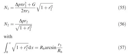
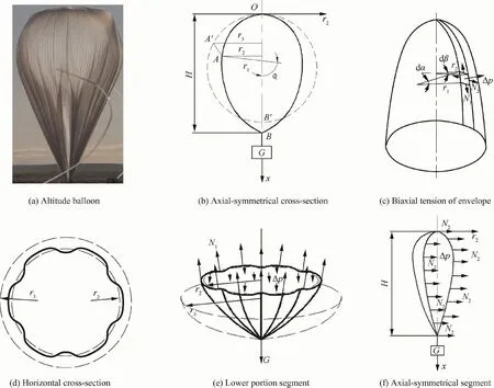
Fig.14 Natural-shape balloon with a payload.

whereN1andN2are the meridional and circumferential envelope tensions,respectively;Gis the payload;Δpis the pressure differential across balloon envelope;r2is the equivalent rotating radius;r3is the rotating radius of high-altitude balloon without the payload;andRbis the radius of balloon sphericity.
Eqs.(55)and(56)are the solutions of meridional and circumferential envelope tensions,which are the functions in regard to the equivalent rotating radiusr2and the pressure differential Δpacross balloon envelope.Eqs.(57)and(58)represent the circumferential constraints of balloon envelope,i.e.the meridional circumferences of the balloon envelope with and without a payload are constant.
With an increase in ascending altitude,the partially inflated shape and volume of balloon naturally increases and the fine wrinkling and folds decrease.At the floating altitude,the shape always fully inflates and the fine wrinkling and folds disappear.In practice,the density,temperature and pressure of atmosphere and lifting gas vary with the increase in altitude,changing the pressure differential across balloon envelope.The changes in density,temperature and pressure of the lifting gas are attributed to the heat transfer across balloon envelope.As a consequence,it is important to evaluate the steady equilibrium temperature within high-altitude balloon in the envelope tension analysis at ceiling floating altitude.Simplified thermal equilibrium models have been proposed to simulate the convective and radiative heat transfer,to estimate emission and absorption heat of balloon envelope and lifting gas,and to predict steady equilibrium temperatures at day and night times(shown in Fig.15).49
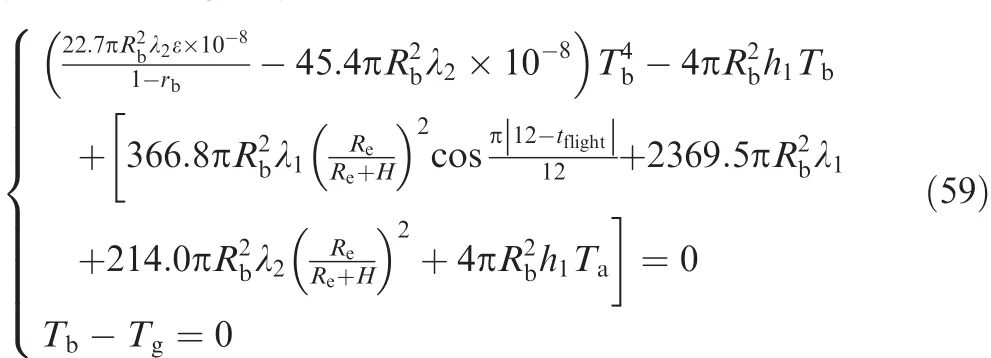
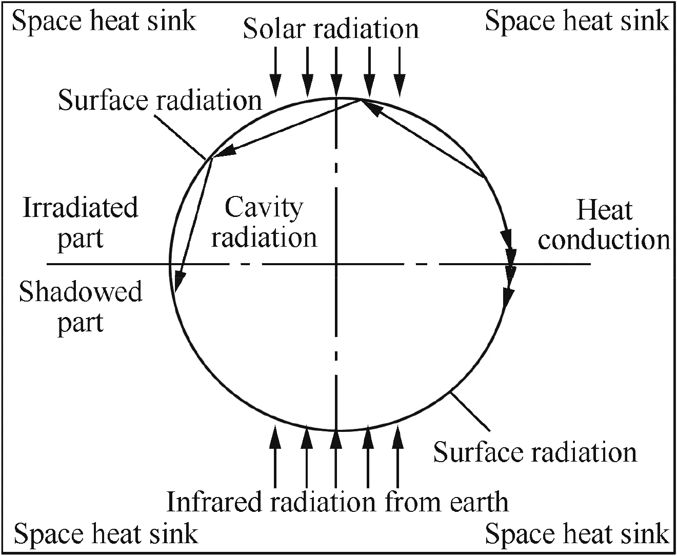
Fig.15 Thermal model for high-altitude balloon.
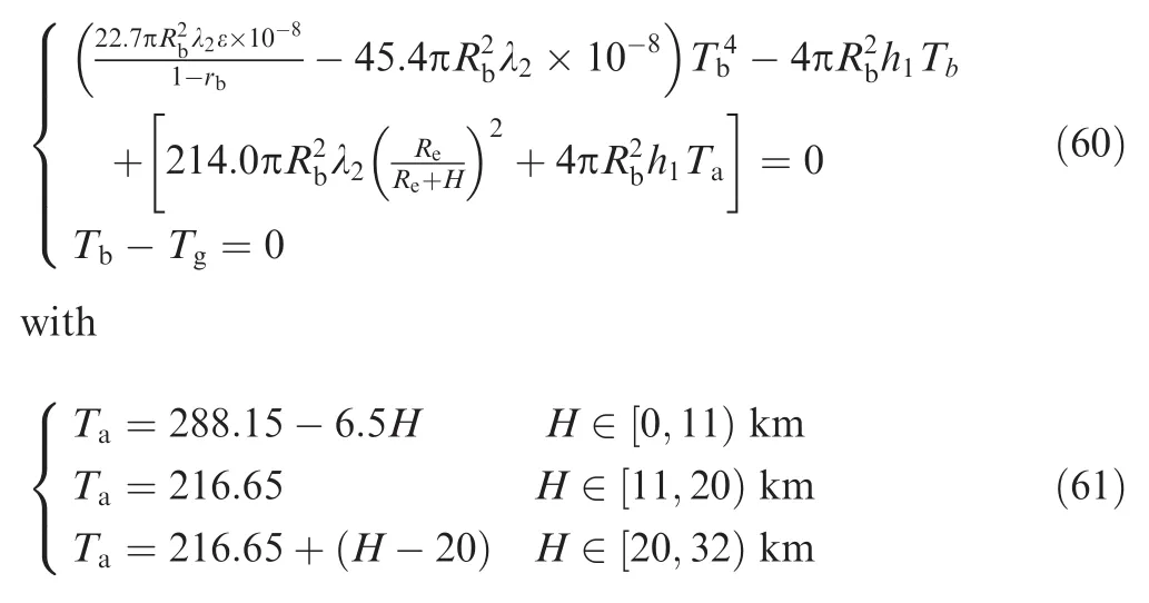
whereHis the altitude over the sea-level on the Earth;h1is the convective heat transfer coefficient between ambient air and balloon envelope;rbis the reflectivity of balloon envelope;Reis the radius of the Earth;tflightis the time at the balloon location;Ta,TbandTgare the absolute temperatures of ambient air,balloon envelope and lifting gas,respectively;λ1and λ2are the absorptivity of balloon envelope to directly incident from the Sun and to infrared radiation emitted from the Earth,separately;and ε is the infrared emissivity of balloon envelope.
From Eqs.(59)and(60),the steady equilibrium temperature of high-altitude balloon can be evaluated by accounting for the heat transfer mechanism and the thermal environment effects from the radiative properties of balloon envelope.Notably,as shown in Eqs.(59)and(60),no convective heat transfer between lifting gas and balloon envelope exists within the thermal equilibrium balloon(orTb=Tg).In fact,usually,the convective heat transfer still takes place until balloon thermal equilibrium(i.e.,Tb≠Tg).
7.4.Deployable ultra-thin-walled lenticular composite boom
Deployable and foldable thin-walled composite booms such as those shown in Figs.16(a)and(b)are finding wide application in aerospace field.These can be idealized as a curved beam with the biaxial-symmetrical lenticular cross-section consisting of concave and convex tangential circular arcs described by a multinomial function.Thus,on the basis of apt deformation approximations and geometrical assumptions,a geometric model can be derived to evaluate the fold deformation and in-plane strain as shown in Figs.16(c)and(d).An analytical solution can be deduced to predict the interlaminar shear stress on the bonding interface based on the linear-elastic constitutive equation founded on micromechanics.Flattening and curling deformation tests were performed on the deployable and foldable thin-walled composite boom.Good correlation was achieved between the predictions and the experiments.50
A corrugated Flexible Composite Skin(FCS)made from the composite booms was proposed for morphing aircraft;this can be extended through pure elastic deformation during a large deformation process as shown in Fig.17.Like in the previous case,a geometric model was derived for describing the extensional deformation of the FCS from apt deformation approximations and geometrical assumptions(see Fig.18).An analytical solution was deduced for evaluating the mechanical properties of the FCS in an extensional deformation process based on equilibrium equation and composite laminate theorems.Flattening and curling deformation tests were performed on the ultra-thin-walled composite boom and static tensile tests were carried out on the FCS specimens.Good cor-relation was again achieved between the predictions and the experiments.51
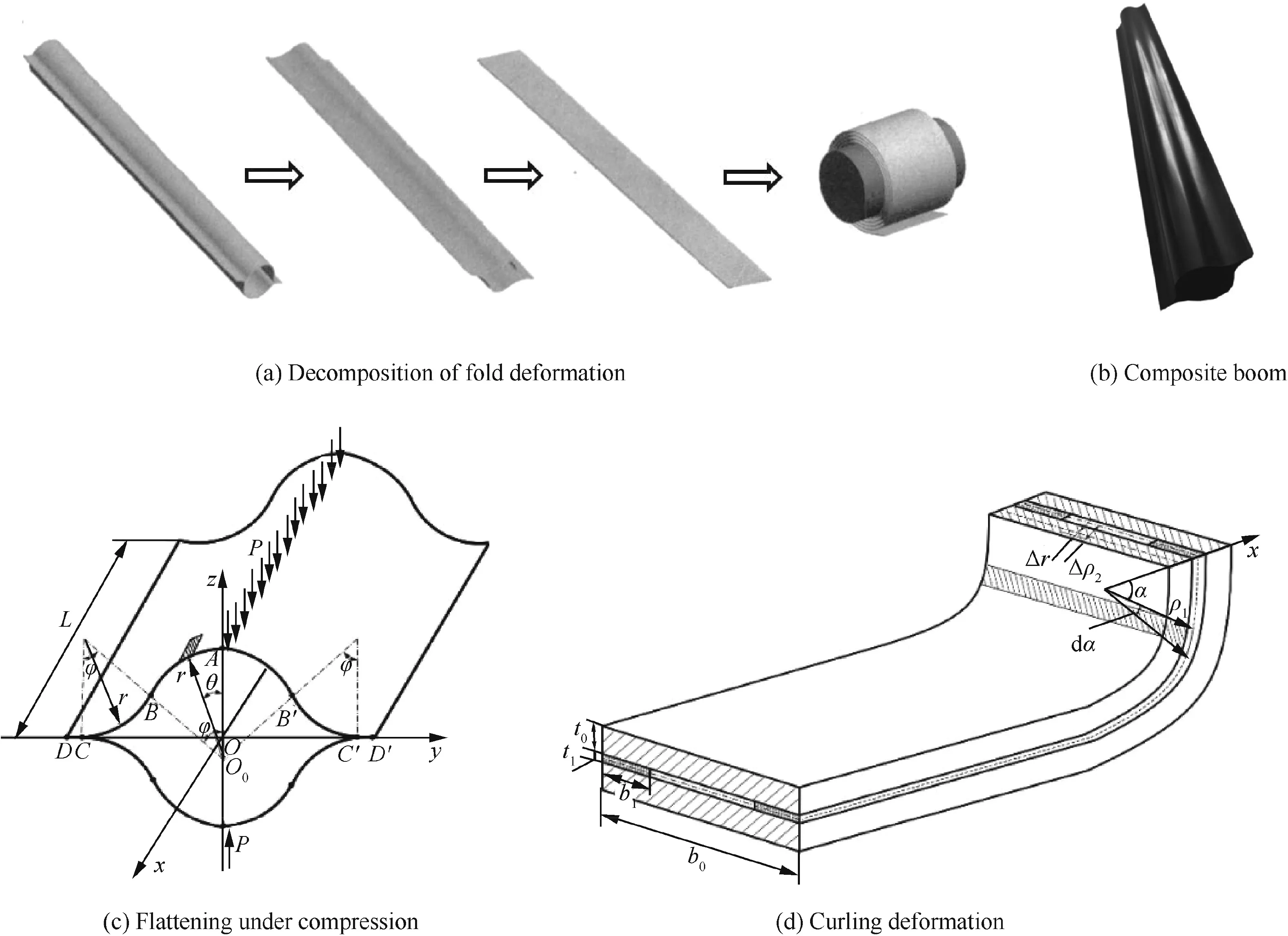
Fig.16 Geometrical configurations of ultra-thin-walled composite boom.
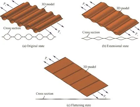
Fig.17 Functional mechanism of the flexible composite skin.
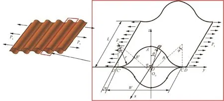
Fig.18 Geometry of FCS under tensile load in extensional deformation.
The thermal behavior of a thin-walled composite boom in a space environment is an interesting and topical area of enquiry.However,it is difficult and expensive to model true space thermal environment for determining thermal behavior of thin-walled composite boom.In literature,52,53space environment modelling tests were performed on a thin-walled composite boom to obtain thermal properties and ascertain thermal buckling behavior of a thin-walled composite boom.Further,FE models were generated to simulate the temperature pattern,thermal deformation and buckling.Good agreement was achieved between simulations and experiments.However,the ultra-low temperature is much harsher for the test system,and so the thermal distortion of thin-walled composite boom could not be measured in tests.Despite this limitation,the tests shed new light on our understanding about thin-walled composite booms in space environments.
8.Closure
The focus of this paper has been to outline new aspects on structural integrity.New findings and advances in engineering approaches,experimental methods,numerical algorithms and understanding of failure mechanisms on structural integrity have been highlighted.Furthermore,the probable problems and issues for further work have also been identified.This effort possibly constitutes a good basis for the next stages of further works on structural integrity.
Acknowledgements
This project was supported by the National Natural Science Foundation of China(Nos.51375033 and 51875021).
杂志排行
CHINESE JOURNAL OF AERONAUTICS的其它文章
- Recent development of casing treatments for aeroengine compressors
- Recent advances in physical understanding and quantitative prediction of impinging-jet dynamics and atomization
- Design and simulation of an innovative cylinder fabricated by selective laser melting
- Application of reliability technologies in civil aviation:Lessons learnt and perspectives
- FEC design for remote control and data transmission of aeronautic and astronautic vehicles
- Performance limitations in trajectory tracking control for air-breathing hypersonic vehicles
