Recent development of casing treatments for aeroengine compressors
2019-01-16XiaofengSUNXuDONGDakunSUN
Xiaofeng SUN,Xu DONG,Dakun SUN,*
aFluid and Acoustic Engineering Laboratory,Beihang University,Beijing 100083,China
bCollaborative Innovation Center for Advanced Aero-Engine,Beihang University,Beijing 100083,China
KEYWORDS Casing treatment;Compressor;Compressor stability;Rotating stall;Stall margin
Abstract Casing treatment is a mature stabilization technique which has been widely applied on aero-engines for modern aircrafts and turbo-chargers for automobiles.After the investigations of half century since the 1960s,this technique has been well developed for various configurations with different effectiveness.From the perspective of stabilization mechanism,this paper roughly categorizes the configurations of casing treatment into two types:traditional ones which work by affecting the flow structure of blade tip region;a novel one named as Stall Precursor-Suppressed(SPS)casing treatment.The effectiveness of both types will be demonstrated for their applications on axial compressors and centrifugal compressors with uniform or distorted inlet.And the stabilization mechanism of casing treatments for regular types and SPS one will also be explained respectively.In addition,this review will summarize the methodologies of casing treatments with the numerical simulations for regular grooved configurations and the eigenvalue approach for SPS casing treatment.Looking forward to the future of compressor stabilization,casing treatment technique will still exist as a general and inexpensive option,and the exploration for its effectiveness and mechanism will be deeper with the development of computational fluid dynamics and advanced measurement techniques.
1.Introduction
The compressor stability problem has been recognized as a significant bottleneck for the development of advanced aeroengines,and especially,it severely restricts those fan or compressor design with higher stage pressure ratio.Generally,the compressor stability problem refers to two phenomena:rotating stall and surge.And surge sometimes could be the deeply developed consequence from the rotating stall.So,for earlier time,investigations mainly focused on describing the form of rotating stall and its effects on compressor perfor-mance.1Hence,the early stabilization designs were basically aimed at removing the flow blockage or the stall cell.However,stall inceptions were discovered along with increasingly deep research about the evolution of rotating stall,which inspired many other stabilization methods associated with controlling the development process of rotating stall rather than the already developed stall cells.A well-known stabilization method is the active control which directly counteracts the stall inceptions through inducing antiphase disturbances.In addition,there is a novel casing treatment named as Stall Precursor-Suppressed(SPS)casing treatment which can affect the stall inceptions in a passive way.The mechanism differences between traditional casing treatments and the novel one have also determined their different effects on compressor performance and stability.
1.1.Traditional casing treatments
During the 60s of 20th century,NASA reported series of researches which were aimed at enhancing the stability of compressor with high-aspect-ratio blades,2and that was when casing treatment technique was presented and developed for the first time.The earliest investigation was implemented to study the effect of casing bleeding and blowing at the rotor blade tip on compressor performance and operating range.And in that report,2it was found that the slotted or grooved or porous casing could also have effect on compressor performance and operating range even without air bleeding or blowing.Since then,more attentions were paid on varying casing configurations to improve compressor flow structure for wider stall margin range.After that point,numerous investigations about casing treatment of various configurations were conducted with being applied on both low-speed(subsonic)compressors3,4and high-speed(transonic)compressors.5,6Among these researches,the most common designs for casing treatments are axial/chordwise recesses or circumferential grooves at the inner side of casing.3-11
Through the primary explorations on this stabilization approach,some general conclusions have been summarized:(A)a properly designed casing treatment can enhance the compressor stability;(B)the effectiveness of casing treatment is customized to one compressor,and its capability would be failed when being applied to another compressor;(C)the use of casing treatment nearly always change the compressor performance,mostly decrease the overall efficiency;(D)for some minority cases,the grooved casing can increase the overall efficiency but without significant stability improvement;(E)there is no specific criterion for designing the casing treatment aimed at different demands and different aerodynamic configurations.Thus,if it is for practical applications,how to design a better casing treatment has become an overwhelming problem.Investigations were carried out in order to get insight into the mechanism of casing treatment for stability enhancement.12,13It was found that for most successful applications of casing treatments,the treated configurations are all engaged in the casing over the rotor tips(while it can also be applied at the hub beneath the rotor or stator when it is believed that the instability phenomena,stall or surge,were generated from the hub region).This arrangement is mainly due to the knowledge of the stabilization mechanism for casing treatment because it can release the flow blockage at the rotor tips by supplying an additional path for secondary flow.Relevant results have indeed helped to decrease the efficiency penalty and to find the criterion for configuration design.With the development of advanced measurement techniques and numerical simulations,deeper investigations have stretched into the flow details at end-wall region even inside the skewed slots and grooves.14-18And except the existing casing treatment of simple geometry,some more geometrically complex designs can be considered because of the use of 3-D printer machine technique.But it should be noticed that all those casing treatment of conventional configurations still cannot solve the conflict between stability improvement and efficiency loss.Another fact which must not be neglected is that casing treatment can also be applied on the centrifugal turbomachines,not only the centrifugal compressors engaged in aero-engines but also the turbo chargers used by modern vehicles,and some published work has shown considerable successes.19-21
1.2.SPS casing treatments
For many years,researchers have been always looking for the new solutions of casing treatment with also new aspects of the mechanism.Especially when the stall inception was discovered,on one hand this discovery has enhanced the understanding of the physical process of the rotating stall,and on the other hand a new attempt,known as the active stabilization of rotating stall and surge,has fully made use of the concept of stall precursor waves to enhance the compressor stall margin.22Considering the significant effects of the withdrawing fluid near the pressure surface trailing edge and re-injecting it near the leading edge,active injecting flow was adopted at the blade tips.This technique could be regarded as an active application based on the mechanism of conventional casing treatment and the knowledge of stall inception.However,passive stabilization methods with casing treatments should be also noted,in particular when they can affect the stall precursor waves in a passive way.Since 1990s,a novel casing treatment which can suppress the stall precursor or affect its evolution,rather than only improve the blade tip flow structure has been suggested and developed by our laboratory.23-29The basic idea is to design a casing treatment which can affect the pressure waves in the compression system as a ‘‘soft” boundary condition or an additional damping for the dynamic system.23Investigations about this novel casing treatment have been systematically carried out during the past twenty years for both methodology24and experiment.25Based on its mechanism,this novel casing treatment is named as Stall Precursor-Suppressed(SPS)casing treatment,which means that it can suppress the amplification of stall precursor waves and improve the stability margin.Through the equivalent surface source method,the SPS casing treatment can be modeled as an impedance boundary condition,which can be included in a 3-D stability theoretical model.26Thus,an optimization design strategy which can take the major geometry parameters of SPS casing treatment into account has also been developed naturally.And besides this,these optimized configurations have been tested on both low-speed compressor rig25and transonic compressor rig,25,27and then the detail investigations aimed at the optimal design were conducted to fully assess its performance with both uniform and distortion inlet conditions.28,29Existing results show that SPS casing treatment can well improve the compressor stability nearly without inducing additional efficiency loss at the design point,and its application can obviously decrease the amplitude of pressure perturbations for circumferential modes(which contain the stall precursors)before the stall onset.It should be noted that,the existing casing treatments in traditional configurations have received numerous successes for actual applications,whether on axial compressors or centrifugal compressors.And there is still much work for us to have further explorations on SPS casing treatment and its practical use.
The following parts will firstly discuss the effectiveness of both traditional casing treatments and SPS casing treatment of which the advantaged performance on stabilization will be well demonstrated.The different performances are determined by the different perspectives about the compressor instability as well as their mechanisms.So,the other part will review the relevant investigations about the influences of regular configurations on compressor flow field and the mechanism of stall-precursor suppression.Besides,the different design methodologies of traditional casing treatments and SPS casing treatment will be emphasized in an independent part.The‘‘trial and error” design method for most traditional casing treatments is still a dominant methodology,while the design for SPS casing treatment can be instructed by a 3-D stability model which can consider the effects of SPS casing treatment as a boundary condition.Finally,a further discussion will be carried out to express some prospects on casing treatments of this paper.
2.Rotating stall
As mentioned in the introduction,rotating stall is a typical compressor instability phenomenon.The typical compressor characteristic with rotating stall is shown as Fig.1 in which the rotating stall immediately causes the pressure ratio decrease,or in other words,the rotating stall makes the compressor can only operate with a much lower pressure ratio compared with the design point.And when rotating stall happens,an accepted mature solution to unstall is opening the throttle and increasing the flow rate as indicated by the black arrows.While,for most compressors,they require a much larger flow rate to unstall than that at which the stall first occurred.This phenomenon is usually considered as hysteresis and can be a significant problem for operating any compressors when rotating stall might occur.
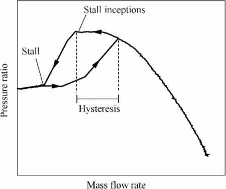
Fig.1 Characteristic of compressor with rotating stall.

Fig.2 Sketch of rotating stall.
As mentioned above,nearly all the pioneer investigations on rotating stall mainly focused on describing the stall pattern,such as Fig.2.A classic description about rotating stall is that a local flow separation which initiates in one blade passage will bring about a local blockage and affect the incident angles of its neighboring blade passages,and this spread will cause a rotation movement of the flow separation region relative to the blades rotation.In this description,the flow blockage plays an important role for the formation of rotating stall.For this reason,a direct stabilization intention is to remove the flow blockage which mostly exists at the blade tip region through actuators or structures,and casing treatment is a typical technique based on this design guideline.Traditional casing treatments usually are with the porous configurations overlapping the blade tip to release the flow blockages,and in order to have significant effects,the perforated ratio is usually more than 50%.
Before the initiation of rotating stall as shown in Fig.1,stall inceptions could be captured through the circumferentially arrayed dynamic pressure sensors.Two common types of stall inceptions were discovered and defined as the indicators of rotating stall,as shown in Fig.3,which are the dynamic pressure signals from channel 1(CH1)to channel 8(CH8).The existence of stall inception is related to the dynamic feature of compressor system,which reflects the evolution process of small disturbances in flow field with the restriction of system damping.From this point,stall inception is the nearest flow perturbation to the stall onset but which cannot amplify into rotating stall because of the system damping.Therefore,technically,before the appearance of stall inception,all the flow disturbances could be the factors which would lead to a detectable stall inception,and all these flow disturbances can be treated as stall precursor waves.
From the time-resolved evolution process of rotating stall such as Fig.4,which shows the Power Spectrum Density(PSD)distribution in both frequency domain and time domain,it is obvious that the stall precursors are broadband disturbances existing in the flow field,and some of them with particular frequencies will be directly amplified into rotating stall.So,the SPS casing treatment is designed to suppress the stall precursors in broadband,its effecting target is the unsteady perturbation waves rather than the fully developed stall cell.Broadly speaking,compared with the traditional casing treatment which is aimed at improving the ‘‘developed”result( flow blockage caused by rotating stall),the SPS casing treatment prefers to influence the ‘‘developing” process of flow disturbances before rotating stall.Besides,the traditional casing treatments are usually designed through ‘‘trial and error”,and the effects on flow field nearly always reduces the compression capability and overall efficiency of compressor;while at the same time,the design of SPS casing treatment can be instructed by a 3-D stability model,and it has only slight effects on compressor performance because of its mechanism as well as the novel configuration.
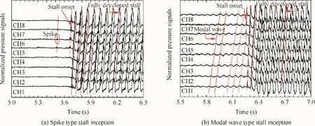
Fig.3 Two types of stall inceptions.
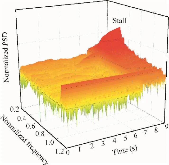
Fig.4 Dynamic evolution of rotating stall.
3.Effectiveness and mechanism of traditional casing treatments
3.1.Effectiveness
Literatures referenced in the introduction have well indicated the effectiveness of casing treatment on stall margin enhancement for compressor system.This part will explain the effectiveness of traditional casing treatments in terms of the stabilization capability of casing treatment and the penalty of peak efficiency in detail when this technique is adopted on both axial compressors(mainly)and centrifugal compressors.And then the performance of SPS casing treatment will be demonstrated individually later.
3.1.1.Axial compressors
3.1.1.1.Experimental tests.As mentioned in the introduction,it seems that the benefits of casing treatment were discovered by accident.2Chasing down this discovery,NASA Lewis carried out series tests focusing on the effects of porous casing treatments in different configurations.8,14Mostly,casing treatments applied on axial compressors are installed overlapping the rotor blades in the inner side of casing,as shown in Fig.5.The insert part is indicated as casing treatment,and this part can also be installed at the rotor or stator hub as a hub treatment.
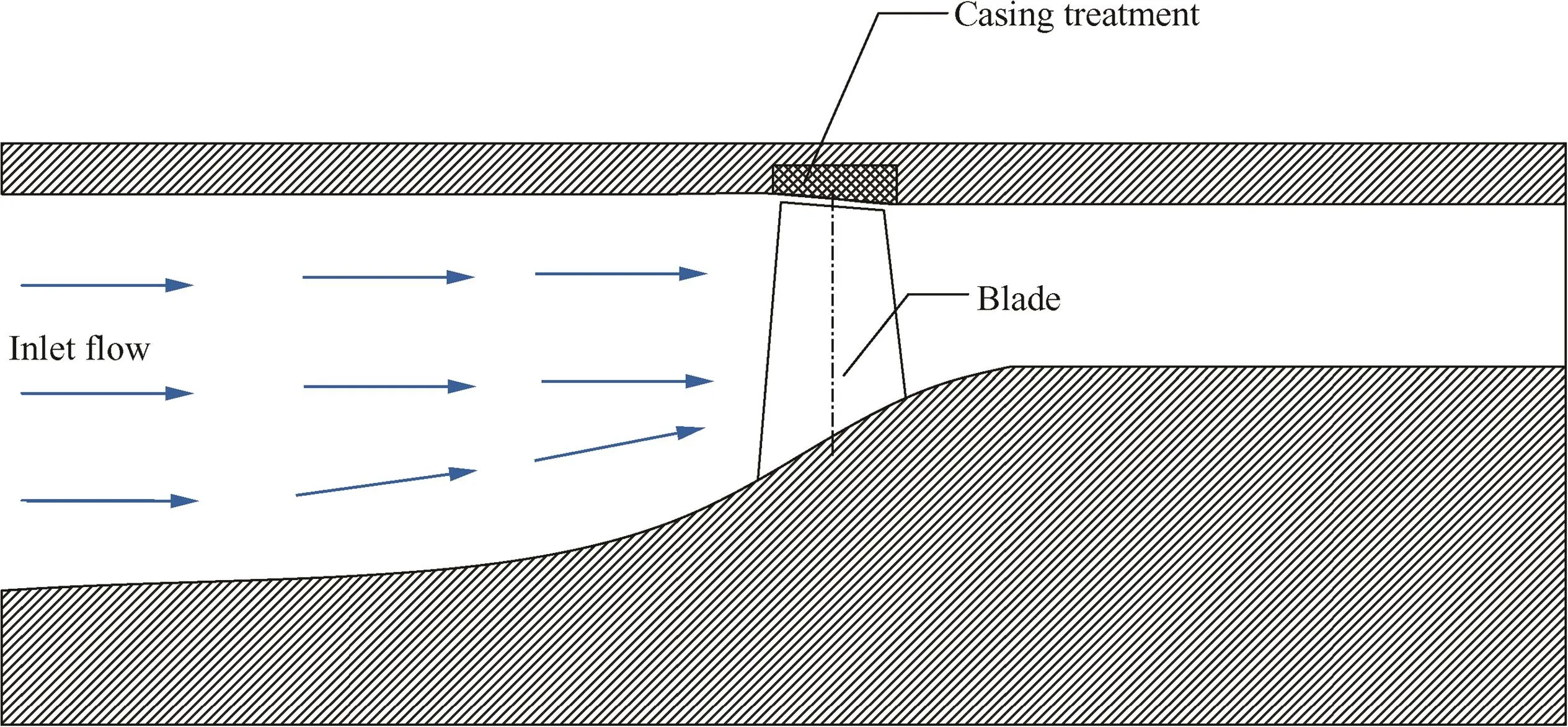
Fig.5 Installing of casing treatment.
In the research carried out by Osborn et al.at NASA Lewis,8nearly all the configurations which were able to be designed at that time were considered and tested.There are mainly five types of casing treatments engaged in this report,as shown in Fig.6.8They are perforated casing with back chamber,honeycomb casings with cell cavities in different depths,circumferentially grooved casing,axially slotted casing and skewed slotted casings in different geometries(skewed angle/axial length/cavity depth etc.).And based on the previous investigations reported by NASA,a single rotor that was tip critical was used to test the effects of these casing treatments.Results presented in this report illustrated the performance curves of single rotor for uniform inlet flow with a solid casing and with all these casing treatments and the performance curves of the rotor for radial and circumferential inlet distortions with solid casing and selected casing treatments.
Performance results for three types of casing treatments with uniform inlet flow are shown in Fig.78(in which the equivalent weight flow is shown in lb/s,1 lb=0.45359 kg).There are two lines indicating the stall limits of solid casing case and casing treatment case of different operating speeds(in percentages of design speednd).Gap between these two stall-limit lines represents the stall margin improvement which is the key effect of casing treatment.Although these performance results have clearly show out the stabilization degrees of different casing treatments,there was no detail comparison between the whole pressure-rise curves with and without casing treatments,which means that the stability benefit may be compared with other performance degradations such as compression ability.Aiming at this concern,Takata and Tsukuda3carried out some experiments on a low-speed compressor to investigate the effects of casing treatment on the compressor performance and on the flow through the blade row as well as the flow within the treatment slots.In that investigation,they declared the skewed slot and axial slot casing treatments had better ability on stability improvement.
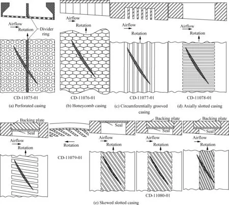
Fig.6 Casing treatments of different configurations.8
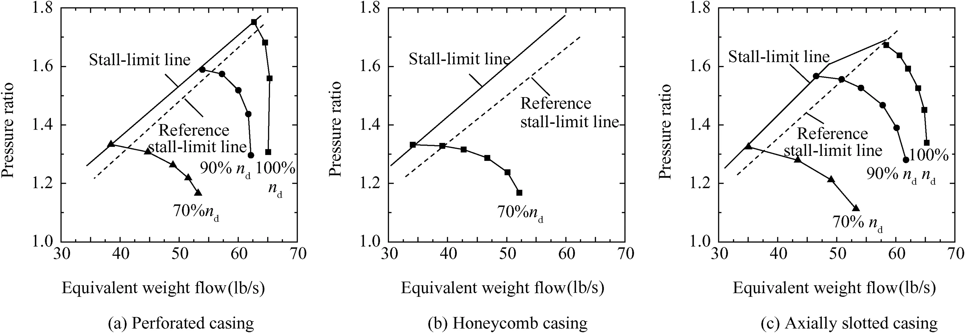
Fig.7 Overall rotor performance for different casing treatments(uniform inlet flow).8
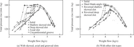
Fig.8 Effect of casing treatment on overall performance(tip clearance 0.6 mm).3

Fig.9 Effects of casing treatment on blade loading(tip clearance 0.6 mm).3
They presented the comparison between the whole pressure-rise curves with and without casing treatments,as shown in Fig.8,3so that the effect of casing treatment on overall performance,not only the stall margin improvement but also the compression capability(the pressure rise is shown in the millimeter of water,mm Aq),could be well demonstrated.The obvious changes of the speed lines indicated that the tested casing treatment had influenced the flow through the blade row as well as the radial distribution of blade loading.Specifically,the radial distribution of axial velocities at stall point and radial distribution of total pressure loss coefficients at dif-ferent operating conditions(the ‘‘Th.opening” values show the throttle opening positions for different operating conditions)were shown in that paper.In Fig.9,3the radial distribution of axial velocities indicted the influence on the flow through the blade row and the radial distribution of total pressure loss coefficients represented the additional flow losses induced by casing treatment rather than through illustrating the overall efficiency of compressor.Besides,based on the results of flow structures at casing slots,a possible mechanism for which the casing treatment is considered to improve the stall margin was proposed for the first time.At that time,people started to believe that the momentum interchange between main flow and reinjection flow played an essential role in the stabilization mechanism of casing treatment.
By reviewing the early researches,Greitzer et al.30gave a fundamental criterion for the application of rotor casing treatment with a general comments on rotating stall which considered there were two modes for compressor to be stalled:blade stall and wall stall.And it was believed that only the case of wall stall was worth to be(or could be)improved by casing treatment.They also referred some common trends for using casing treatment:(A)the use of a grooved casing can provide substantial improvement in compressor stall range over a smooth wall casing,(B)the use of a grooved casing can lead to somewhat increased efficiency over a smooth wall casing,(C)those configurations which are best for improving stall range have some performance penalty(i.e.,efficiency)associated with their use,(D)those configurations which give increased efficiency are not as effective in increasing the stall range,(E)the same trends with configuration hold over the entire range of blade tip Mach numbers(MaTIP)tested-for example,those configurations which have a substantial effect on stall margin atMaTIP=0.15 also have a substantial effect atMaTIP=1.5.30Focusing on the influence of casing treatment on compressor efficiency,Fujita and Takata31carried out a particular explanation,and addressed that the efficiency loss was the major disadvantage of casing treatment.And at the same time,they also investigated the effects of casing treatments not only by varying the casing type but also varying the geometry of casing treatment.Relevant results are summarized in Fig.10,31in which the maximum efficiency decrease continuously with the increase of stall margin improvement,and there is not much sensitivities to the geometric variation.
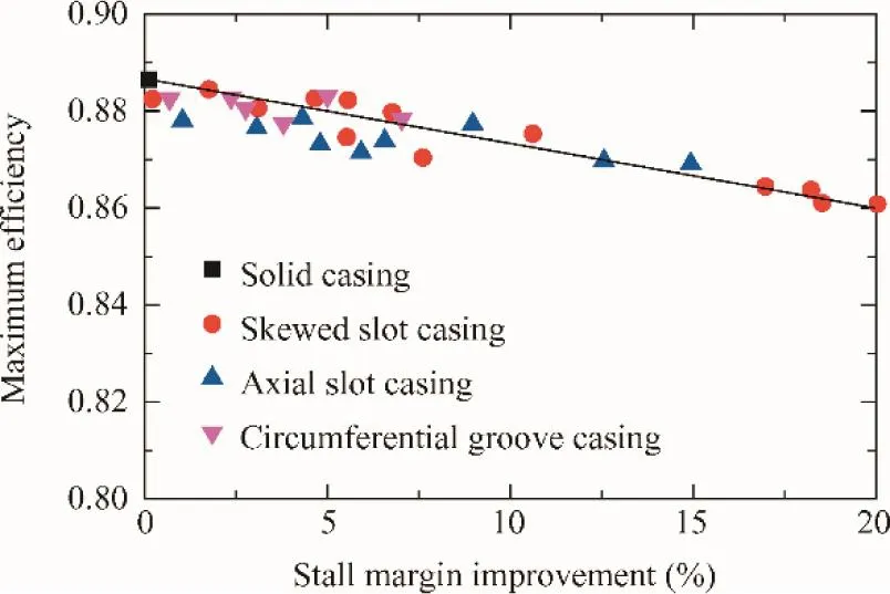
Fig.10 Relation between rotor maximum efficiency and stall margin improvement.31
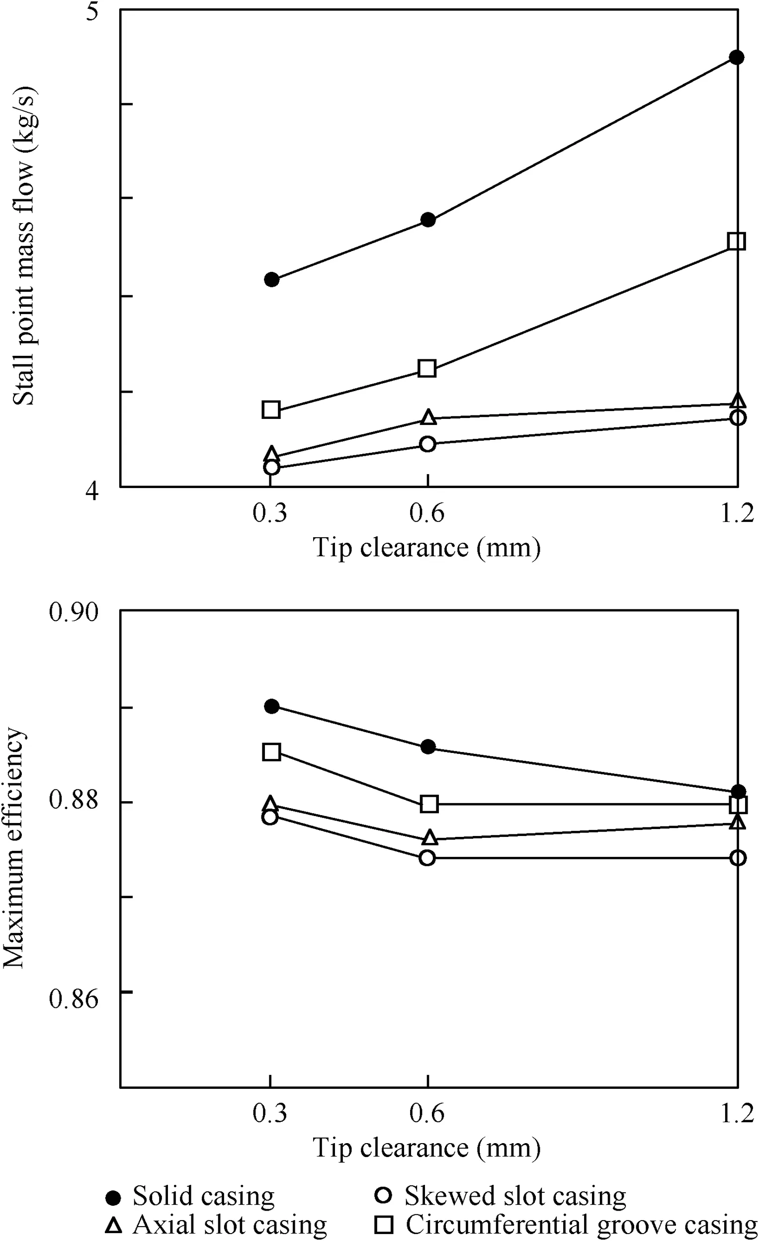
Fig.11 Influence of tip clearance.31
Besides that,they have also conducted some preliminary studies on the influence of tip clearance which was quite essential for the possible mechanism of casing treatment,results are shown in Fig.11.31It seems that casing treatment would not change the trend of the influence of tip clearance:with the increase of tip clearance the maximum efficiency decreases and mass flow at stall point increases.And based on just a few data points in Fig.11,a rough effect might be summarized as that the efficiency loss increases and the stall margin improvement increases as the tip clearance is raised until the tip clearance becomes large enough.
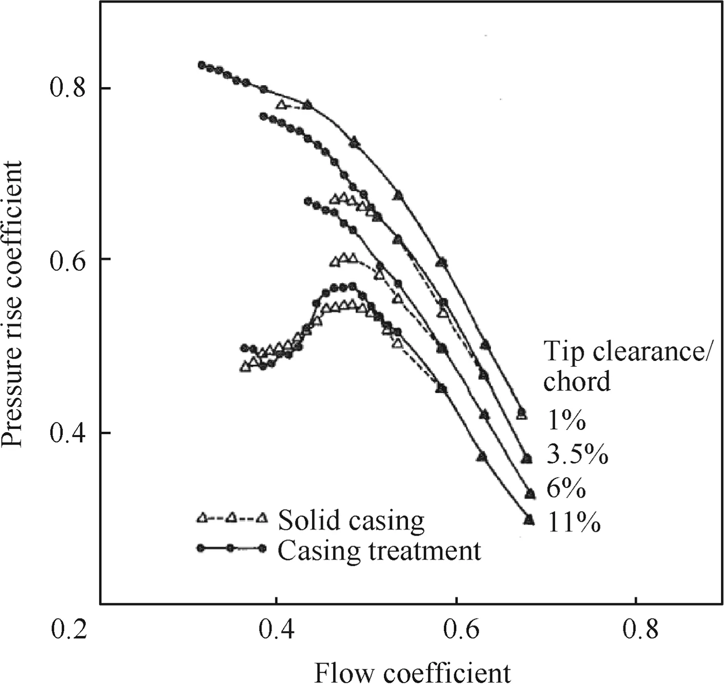
Fig.12 Static pressure rise characteristics at various tip clearances.15
Smith and Cumpsty15also investigated the effect of tip clearance on the stabilization ability of casing treatment,as shown in Fig.12.When the tip clearance is small,the casing treatment can obviously enhance the compressor stability,and the stall margin improvement becomes limited when the tip clearance is very large.There are two ways to interpret this phenomenon:(A)the stabilization ability of casing treatment would be restricted by large tip clearance;(B)the application of casing treatment can mitigate the detrimental effect of large tip clearance.No matter what explanation it is for this effect,this result has well demonstrated the relationship between casing treatment and tip clearance,which is quite conducive to the application of casing treatment.
3.1.1.2.Numericalsimulations.Numerical computation method has also been widely used to assess the effects of casing treatment for recent years.While,among all these types of casing treatment,the grooved one is the simplest configuration,so most CFD investigations are focusing on the grooved casing treatments of different geometric parameters.32,33The first attempt for numerical simulation was carried out focusing on the circumferentially grooved casing treatment for which the configuration is symmetric and simple.An earlier work was conducted by Houghton and Day,10,11and the effects of circumferentially grooved casing treatment were carefully investigated and analysed through both experimental test and numerical simulation.Subsequently,Du et al.32investigated the impact of single grooved casing treatments at different axial locations on compressor stability and even on stall inception.Experimental and numerical pressure rise coefficient curves versus the flow coefficient for the solid casing and two groove casings are shown in Fig.13.32The stall margin improvements calculated by CFD methods show a good agreement with the experimental results.Through these results,they have also mentioned that the CFD methods would usually overestimate the stall margin for the three casings because of the circumferential irregularities of the test rig and the uniform assumption in circumferential for calculations.By tracing and analysing the time-resolved static pressures,the calculated result of the stall inception process with grooved casing is also demonstrated as shown in Fig.14.32FromT1toT3(Tis different time step),the result captures the whole process of rotating stall from initiation to fully development.A series of similar results have uncovered the influence of grooved casing treatment on stall inception and stall process,which should be considered as an active attempt to explain the unsteady effect of casing treatment on compressor characteristic rather than the steady overall performance.
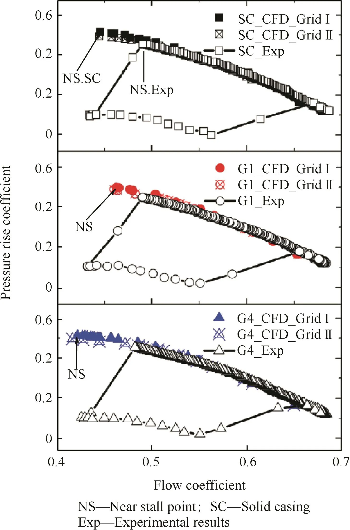
Fig.13 Characteristic lines for solid wall casing,G1,and G4 grooved casing treatments.32
Similarly,more configurations of groove casing treatments were engaged in a CFD analysis carried out by Sakuma et al.33Results in Fig.15 illustrate the effects of circumferential single grooved casing treatments on the overall total pressure ratio and overall efficiency of NASA Rotor 37.It is noted that the stall margin improvements of different configurations are quite different too,but the overall efficiencies do not change accordingly to the casing configurations.In addition,all these numerical investigations are with the description of flow structures,such as flow in blade passages or blade tip region near the casing treatment,so the relationship between flow and casing treatment can be depicted to explain the mechanism of casing treatment for its stabilization capability.Those work will be further discussed later in this paper.
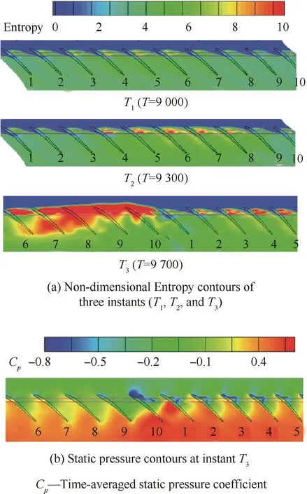
Fig.14 Calculated stall inception process for grooved casing.32

Fig.15 Characteristics plots at shallow and deep groove conditions.33

Fig.16 Self-recirculating casing treatment.34
3.1.1.3.Other investigations.There are also some other types of casing treatments whose geometric properties are different with the traditional ones.34,35For example,Hathaway34proposed a kind of self-recirculating casing treatment of which the bleeding and injecting flow were supplied by two valves rather than the two sides of slot,as shown in Fig.16.This arrangement was an first attempt for modeling the casing treatment(Fig.16(a))and investigated its effect mechanism,and then this configuration was evolved into a new type of casing treatment(Fig.16(b)).Based on the relevant results,this configuration could provide a considerable benefit in compressor stability without inducing loss in efficiency or compression capability.
Another special casing treatment is recessed casing which is usually a simply geometric recess over the rotor blade,as shown in Fig.17(a).35This kind of casing treatment is believed that it can improve the compressor stability by affecting the tip flow through the covering effect.Considering the simply geometric property of the recesses,a statistical model for the effect of this configuration on compressor performance has been developed besides the direct investigations targeting the effectiveness of casing treatment.35This model can summarize the influence of geometric parameters on compressor performance(stable operating range and efficiency),and give an objective assessment for the effectiveness of casing treatment in this kind.A more complex configuration for recessed casing treatment was investigated by Kang et al.,4in which a vaned recess casing treatment was designed and tested.
Although the effectiveness of casing treatments on axial compressors has an available trend and there are already many successful applications,this technique still needs more investigations and attempts because of the complexity of flow instability.With the further exploration for rotating stall and surge,a more effective casing treatment may come from the novel geometric design based on deeper understanding of its mechanism.
3.1.2.Centrifugal compressors
Compared with axial compressors,there are relatively less applications of casing treatments on centrifugal compressors,not only because the stability problem for centrifugal compressor is less severe but also the shroud for centrifugal impeller is quite geometrically complex and very asymmetric.However,with the more and more turbo chargers being applied on modern automobiles,this stabilization technique has been well developed and applied to extend the stable operating range of turbo chargers.
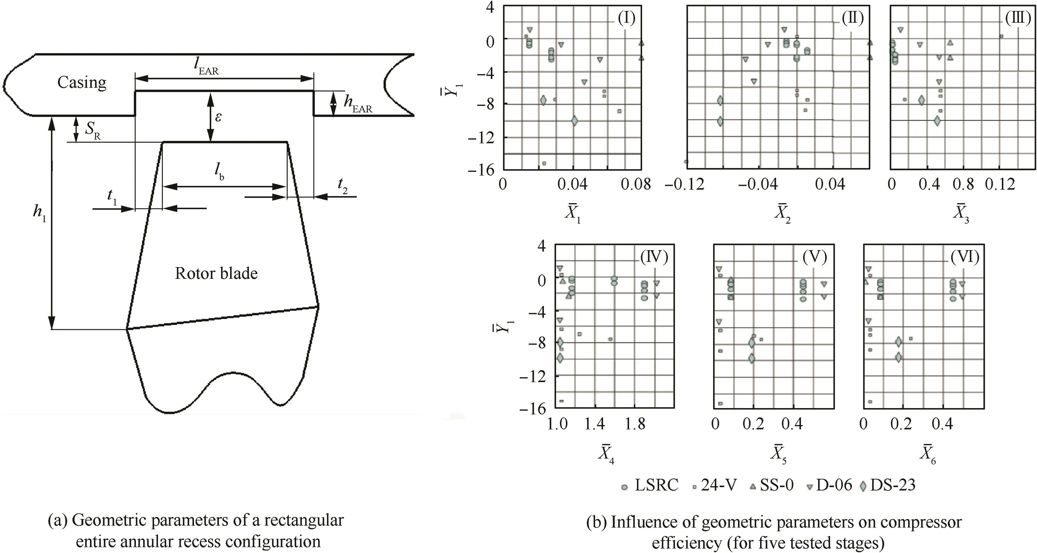
Fig.17 Rectangular entire annular recess.35
An earlier work was carried out by Amann et al.,36in which a centrifugal compressor of an automotive gas turbine was investigated.The stable operating range was restricted by the acceleration process which was required by the automotive duty cycle.For this concern,a circumferential slot surrounding the rotor was applied as a flow relief path which was in the shroud near the impeller tip and connected with a chamber,as shown in Fig.18.36The results of the compressor performance map with and without circumferential slot have shown a substantial improvement for surge margin.Similarly,Wiggins and Waltz37set a circumferential groove casing treatment at the inlet over the inducer,and this arrangement also obtained considerable stability improvement.Unlike the casing treatment applied on axial compressor which generally must be installed over lap the blade leading edge,casing treatment for centrifugal compressor could be arranged at anywhere of the shroud(inlet or outlet,even at the shroud of inducer or diffuser)based on the position of instability initiation.Investigations conducted by Jansen et al.38have well explained this issue.Thirty different methods were tried to improve the stall margin in their paper,while some of them were successful(which means most of them were unsuccessful)and tested on two impellers of different pressure ratios and blade shapes.In that research,the casing treatment was highly effective when it was just over the inducer for the testing with a vaneless diffuser because it was believed that only the inducer had a real contribution to the overall stability(as shown in Fig.19).38When tested with the vaned diffuser and rotating slots at diffuse inlet,the stall margin was extended smaller,but the mass flow at chocking point was unexpectedly increased because of the release of blockage(results of different correlation speeds are shown in Fig.20,38the solid points show the results with slotted inducer or diffuser and the hollow points show the results with solid casing).
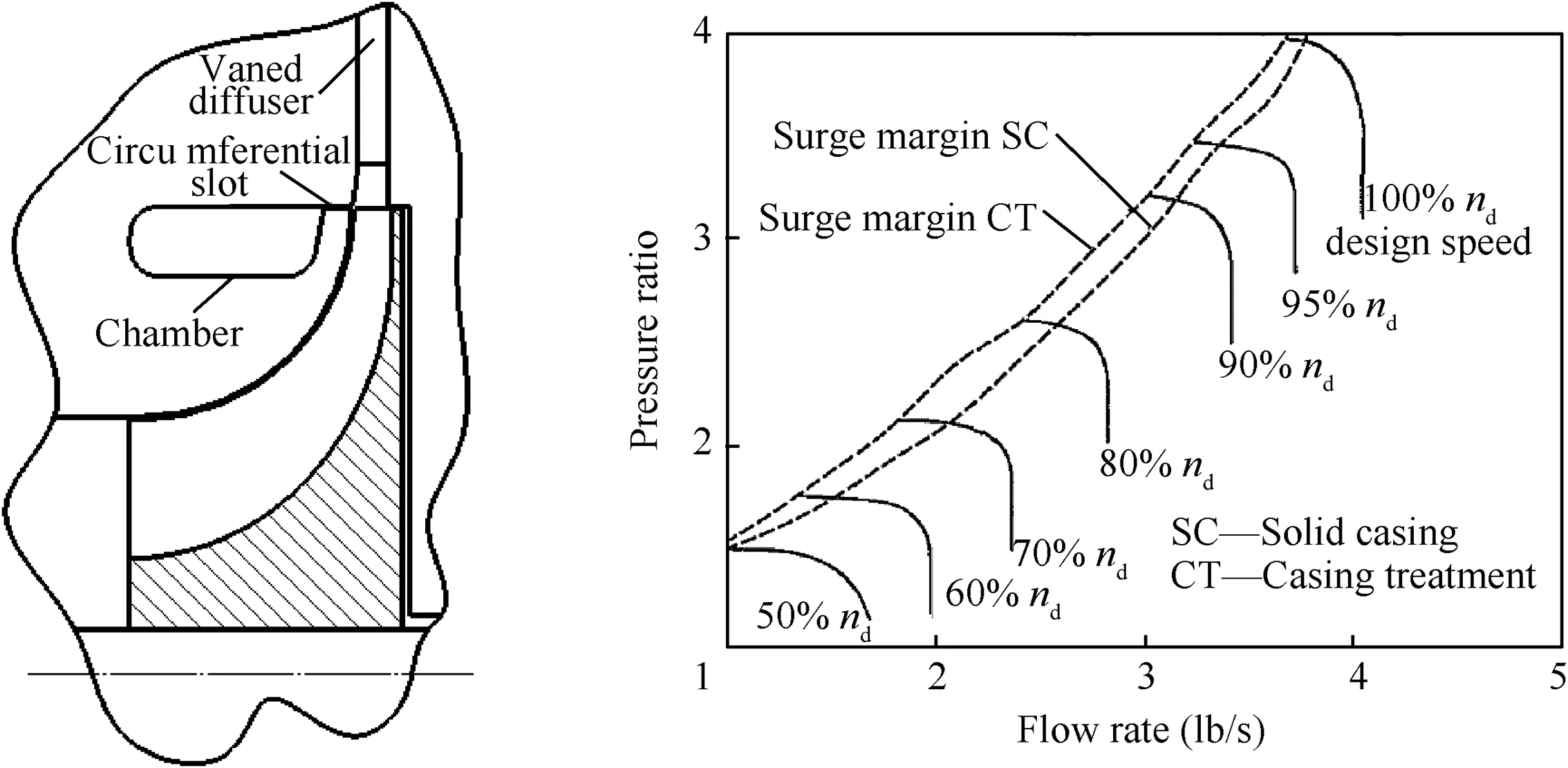
Fig.18 Casing treatment configuration and its effect(1 lb=0.45359 kg).36
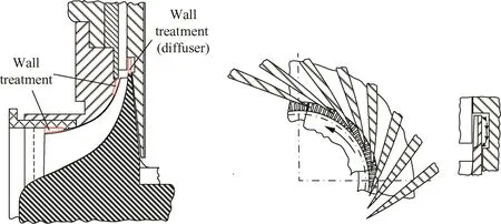
Fig.19 Casing treatment at inducer and at diffuser inlet.38

Fig.20 Performances of test impellers with and without casing treatments.38
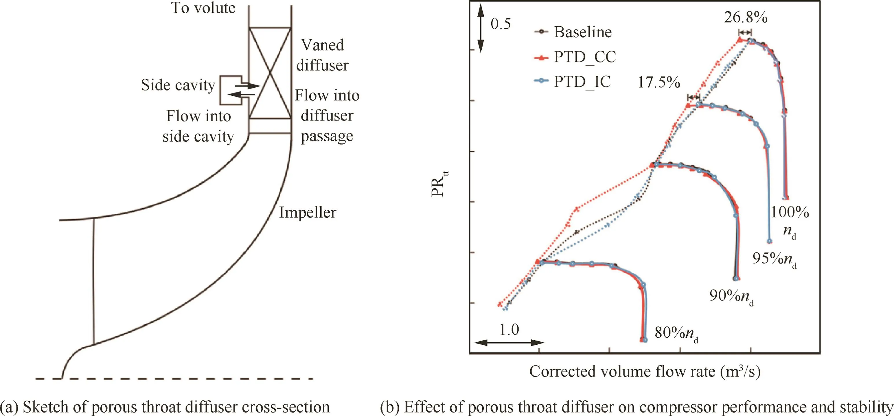
Fig.21 Porous throat diffuser and it effects.21
Fisher39summarized the effects of different casing treatments(axial groove type and circular groove type)on centrifugal compressor and first proposed the impeller recirculation device to enhance the stability margin of turbocharger compressor stage.The impeller recirculation device could obviously improvement the compressor performance in map width and enable single stage compressors to be matched to diesel engines without limiting speed range.Recently,researches about casing treatment applying on turbochargers are quite abundant.19-21Raw19once proposed a Porous Throat Diffuser(PTD)which was a successful casing treatment and this kind of casing treatment has been applied to turbochargers by Ono.20The configuration of PTD mainly consists of openings at the diffuser throat,with a communicating side cavity which can link all the diffuser passages.The latest investigation about PTD is carried out by Galloway et al.,21in which the effects of PTD with Common side Cavity(CC)and Individual side Cavity(IC)were demonstrated.The configuration of porous throat diffuser engaged in that investigation is shown in Fig.21(a)21and the effect of this technique on compressor performance (total to total pressure ratio(PRtt)-corrected volume flow rate)and stability is shown in Fig.21(b).21From the performance results,it is noted that three solid lines are corresponding well to each other,which means the PTD nearly does not change the compressor performance.The PTD with individual side cavity shows no improvement for compressor stability,while the PTD with common side cavity can extend the stability margin by 17.5%at 95%design speed and 26.8%at 100%design speed as indicated.This effect means that the stabilization capability of PTD is related to the cavity condition,and the communication between cavities plays an important role in this situation.The most recognized explanation for this effect is that the porous throat diffuser with common cavity could equalize the pressure at the throat of all diffuser passages and thus average the risk of stall at any one passage.Meanwhile,the effect of PTD on stall inception also has been investigated in that work.
All these studies have supplied enough evidence for that casing treatment is a considerable and effective approach to improve the stability of centrifugal compressors wherever it might be applied,at the inducer or diffuser.An accurate and comprehensive pre-assessment of the objective compressor is the key precondition for a successful application of casing treatment on centrifugal compressor.
3.2.Stabilization mechanism
The effectiveness of casing treatment has close association with its impact on the flow field,especially on the flow structures of end-wall regions.Existing investigations have excavated the mechanism of casing treatment as deep as possible via both numerical simulations and experimental analyses.For most general conditions,the stabilization mechanism of casing treatment could be demonstrated through depicting the flow structures at the blade passages,clearance gaps or even in the groove cavities.Meanwhile,some dynamic properties of the compression system operating with the casing treatment could be reflected in the time-resolved measurements and modal analyses.A general recognition for the mechanism of casing treatments in regular configurations is that the porous casing or grooved casing can affect the flow field and release the tip blockage,through which the stability margin can be improved.So,most investigations attempting to uncover the mechanism of regular casing treatment are concentrated on the flow structure with/without casing treatment and even the interaction between casing treatment and stall onset.
When this stabilization method was first proposed,most tests were conducted focusing on the overall performance of compressors,and only few of them have looked into the flow phenomena in the treated casing or blade passages.The earliest literature which can be traced back was reported by Prince et al.,14which is a NASA report supplied by General Electric company in 1975 about the results of the investigation into the flow patterns and mechanisms by which porous wall casing treatments act to postpone the onset of stall and improve the usefuloperating range.Time-averaged probes,hot film anemometers and B&K pressure sensors were engaged in that investigation for steady-state and transient pressures or velocities measurements.Through the visual observation on a low speed research compressor,the flow phenomenon into and out the cavity of axial-skewed slots was observed.They also confirmed the existence of large circumferential velocities in circumferential grooves,and random flow patterns in all other cavities.Besides these,static pressures were measured on the blade surfaces,through which the modification of pressure loading on blade could be measured and analyzed.Results showed the pressure recovery was improved by the circumferential groove configuration in 50%-75%chord region,so that the pressure loading was shifted,which means almost half of the flow field in spanwise was influenced by casing treatment.Effects of casing treatment on wall boundary layers were investigated as well,and relevant results showed that the circumferential groove treatment had little impact on the boundary layers;the axial-skewed and blade angle slot treatments had little influence too at the stable operating range,but caused substantial decrease in boundary layer momentum defect close to stall.

Fig.22 Unsteady flow in treatment slot(shallow skewed slot casing,tip clearance 0.6 mm).3
As mentioned in Section 3.1,Takata and Tsukuda3carried out some experiments on a low-speed compressor to investigate the effects of casing treatment on the compressor performance,besides they have also looked into the unsteady flow pattern at the casing slots or grooves to penetrate the mechanism of stall margin improvement.They tried to measure the unsteady velocity and pressure perturbation at the casing slots through a special tandem hot wire probe.Results shown in Fig.223are the traces of the rotor blade tip pulse,the flow velocity in the slot,the total pressure in the slot,and the output of the hot wire placed ahead of the rotor respectively from the bottom upward.At the design point(Fig.22(a)),a periodical jetlike flow being discharged from the inside of the slots into the main flow is noted at the blade passing frequency,and the highest velocity of this jetlike flow can reach 40 m/s which is higher than the axial velocity of main flow(25-40 m/s).And the velocity becomes higher when the compressor is operating near stall point,which means the fluid interchange between the slots and main flow become more intense(Fig.22(b)).Fig.22(c)shows the same four traces as Fig.22(a)and(b),of which the operating point is with rotating stall.The magnitude of the jet velocity is modulated by the rotating stall,and the fluid interchange still exists in a high intensity.These results can roughly depict the flow patterns at the casing slots and support a possible explanation for the stabilization mechanism which is close related to the high speed jetlike flow.Although this work conducted careful measurements for fluctuated velocities,the result is still a rough description for flow structures which cannot draw a solid conclusion of the stabilization mechanism of slotted casing treatment.But this attempt indeed gave a interesting direction where the assured stabilization mechanism would be found.
For real flow structure measurements,Greitzer et al.30carried out a careful experiment based on the hypothesis that stall could be categorized as wall stall and blade stall through either of which the stall could initiate.Thus,detailed measurements were conducted in the rotor relative coordinate to capture the feature of the flow in the end-wall region.The relative frame total pressure results,as shown in Fig.23,30indicated that the application of casing treatment could cause a large decrease for the relative total pressure at the rotor exit when present with the wall stall blades,but little change in the relative total pressure field when the stall pattern was blade stall.
A notable investigation which had well considered both the effectiveness and mechanism of casing treatment was conducted by Smith and Cumpsty.15The axial velocity was measured with an angled hot wire which could cover a radial tangential plane 10 mm downstream of the rotor trailing edges.Results in Fig.2415show the contours of axial velocity for this measured region with solid wall casing and casing treatment.From these two contours,the solid casing case shows that the rotor tip is highly staggered and the high loss flow with low axial velocity tends to pile up in the pressure surface corner of casing;and the casing treatment case shows that the low axial velocity region is replaced by a high velocity one as well as high relative total pressure.This comparison looks like that the casing treatment effects on the compressor flow field by withdrawing fluid from the main flow near trailing edge of pressure surface and reinjecting the fluid into the main flow near the leading edge.
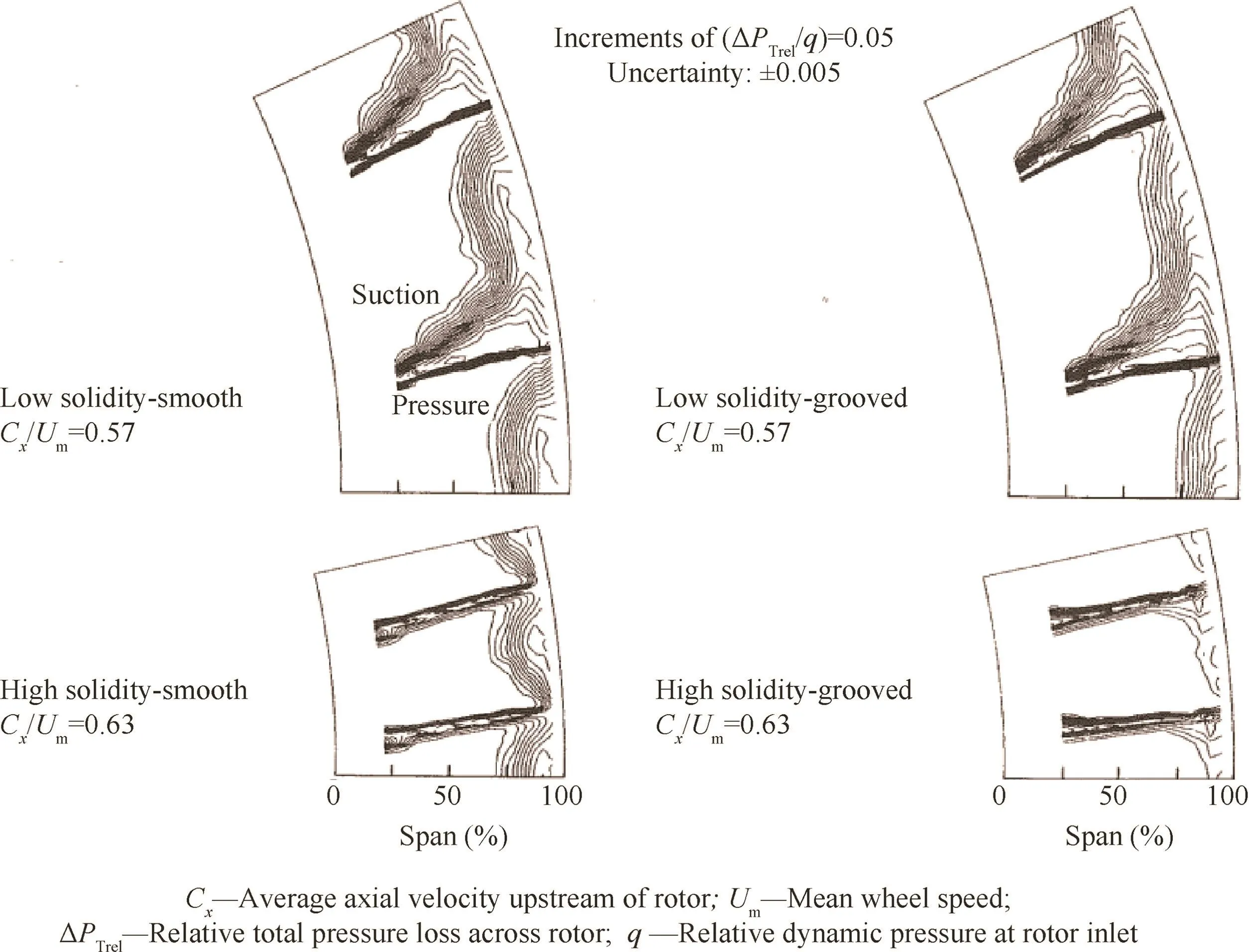
Fig.23 Relative frame total pressure contours downstream of rotor.30
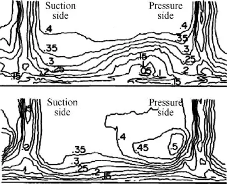
Fig.24 Axial velocity measured in radial-tangential plane downstream of solid wall/treated rotor and nondimensionalized by Um( flow coefficient φ=0.32).15
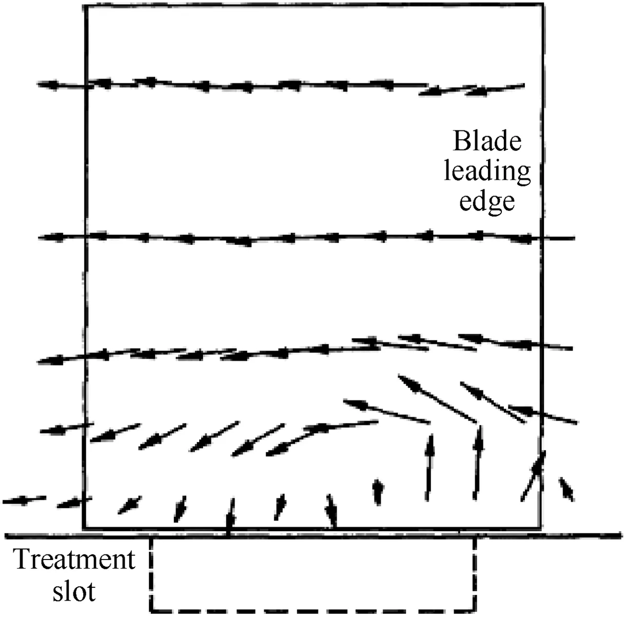
Fig.25 Spanwise flows 20%of pitch from pressure surface(φ=0.34).15
Meanwhile,the velocity distribution in spanwise near the casing treatment slot,20%of the pitch from the pressure surface was measured,as shown in Fig.25.15In this figure,the fluid flows in and out the casing slot is obviously demonstrated.For this reason,the skewed axial slots are relatively easier for this flow interchange with the actuation of rotor blade and so that have a better effectiveness for stabilization.The velocity distributions in axial and radial directions fully demonstrated the flow pattern in the blade passage near the casing wall when slotted casing treatment is engaged in.The particular flow interchange phenomenon was believed by Smith and Cumpsty as the essential mechanism for stabilization.
Except the slotted or grooved casing treatment,mechanism of the vaned recess casing treatment was also experimentally investigated by Kang et al.in 19954by detailed 3-D flow measurements in the end wall region and in the casing recess with a hot-wire.Three configurations of vaned recess casing treatment were considered in this research and measurement results of flow in vane passages are shown in Fig.264(Vais the axial velocity,Vris the radial velocity,Vtis the tangential velocity,Umidis the mid span blade speed andRis the recessed pattern).These results of velocity vectors clearly indicate the recirculation flow phenomena at both high flow rate and low flow rate,and it is confirmed as a clue to the mechanism by which the vaned recess casing treatment effects.
As we know,for modern aero-engines,the overall efficiency is a significant performance index,and even 1%drop of efficiency is also unacceptable for a mature casing treatment design.In recent years,with the development of advanced measurement techniques,some more detailed investigations have been conducted focusing on the blade passage flow and the efficiency loss caused by recirculation flow in the slots or grooves of casing treatments.Emmrich et al.40carried out an experimental investigation by means of detailed time averaged and time resolved measurements on an efficient casing treatment which can enhance the stall margin of the test compressor by 50%with only 1.4%efficiency loss.There are three measurement planes in their research:plane at the rotor inlet,plane at the rotor exit and the plane at the stator exit.Both velocity results and total pressure results of the rotor exit can well demonstrate the effect of casing treatment on the performance and flow structure of the test compressor.The circumferential averaged absolute flow angle(α)results at rotor exit(E2 measuring plane)are shown in Fig.27.40From this figure,there are no significant changes between the SC case and CT case at the maximum efficiency(Max.Eff.)conditions when the operating speed is 12000 r/min.While at the stall point of solid casing case,the averaged flow angle is reduced 10°by the application of casing treatment.This decrease of the incidence angle of the stator is related to the decrease of axial velocity with the throttle process.Considering the stall point of CT case,the maximum change can reach 30°,which is close associated with the separation at the casing wall induced by casing treatment.
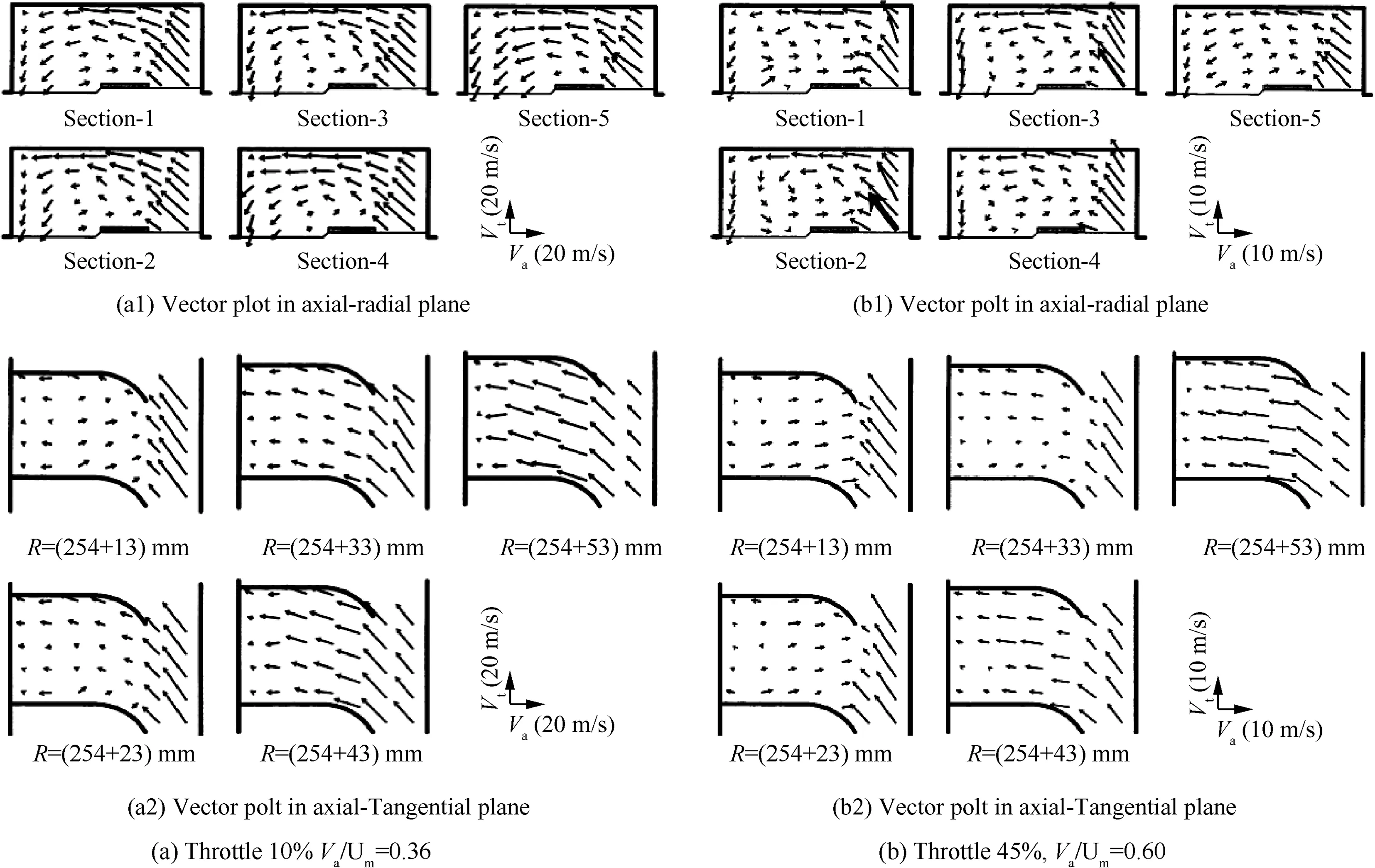
Fig.26 Flow in vane passage of casing treatment.4
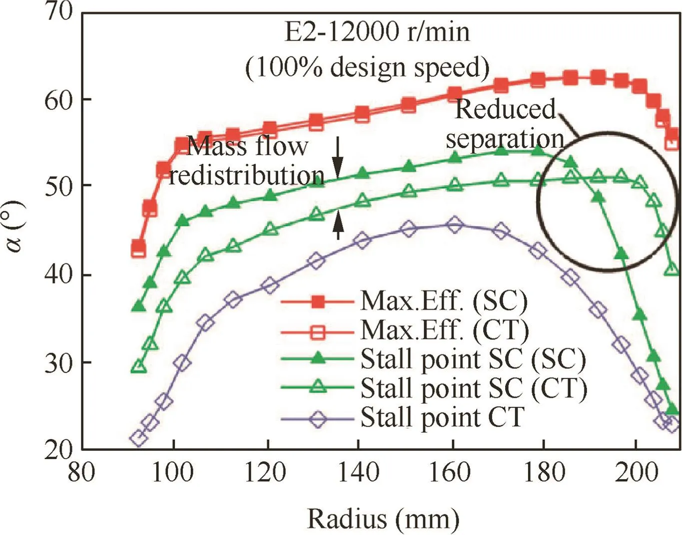
Fig.27 Circumferential averaged absolute flow angle in rotor exit.40
The time resolved flow field at stall point measured by Emmrich et al.40is presented as Fig.28.40This figure makes a comparison of the averaged total pressure(Pt)distributions at rotor exit between solid casing case and casing treatment case.From this comparison,it is noted that the grown blockage effect at the casing wall become more significant.The stabilization influence of the casing treatment can be well observed for the total pressure ratio after the rotor increases and a better aerodynamic performance has be achieved with the application of casing treatment.From this research,there are two confirmed aspects for the stabilization mechanism of casing treatment:the changed flow angle at the rotor exit over the whole span indicates that the blade loading of nearly whole span is influenced by the casing treatment stabilization effects;and the efficiency loss is mostly caused by the separation region induced by casing treatment.These conclusions agree well with the previous investigations.

Fig.28 Snapshot of averaged total pressure distribution in rotor exit at solid casing stall point.40
So far people have already unsatisfied with just depicting the steady flow field or analyzing the pressure traces in time domain.New angle of view has been proposed to explore the more complicated mechanism for the effects of casing treatment on stall inceptions which are quite transient and unsteady.Houghton and Day10declared the importance of stall inception for the effectiveness of casing treatment.Based on their statement,for an effective circumferentially grooved casing treatment,the stall margin improvement increases with the increase of groove number but combined with more overall efficiency loss.Besides,a more important fact is that this trend might only valid when the stall inception of test compressor is spike type.As mentioned above,the mechanism of casing treatment is close related with affecting the flow structure,especially releasing the blade tip blockage via flow bleeding and blowing.A common understanding for spike type stall inception considers that the spike feature comes from the transient tip vortexes with large amplitude.Thus the spike like stall inception seems easy to be impacted by casing treatment because of its stabilization mechanism.However,for the stall inception of modal wave type,it is hard for casing treatment(especially for axial slotted or skewed slotted ones)to establish an effect on the flow perturbation in circumferential mode.
A latest experimental investigation carried out by Brandstetter et al.41by means of the Particle Image Velocimetry(PIV)measurement technique.Results showed the flow field of the blade tip region underneath the casing treatment which has a significant modification compared to the solid casing case.Fig.2941shows the time resolved injection process for axial slot casing treatment,in which the Mach number contours are superimposed.The flow observation technique clear shows the reinjection zones and the shock distribution.Results of this kind could greatly enrich the understanding for the mechanism of casing treatment.
Another notable thing is that for most casing treatments of axially or skewed slotted configurations,the slots exist at just over the blade tip and the blade passage at the same time.This is to say the interactions of slots-blades and slots-blade passages are simultaneous as well as their effects on the compressor.Although there already have been abundant descriptions for the flow structures at the blade tip regions and in the blade passages,it is still complicated to fully explain the mechanism of casing treatments with regular configurations.As for SPS casing treatment,its slots amount is nearly equal to the blade number,which means the flow pattern and the effect of casing slots are relatively more unitary and simpler.
4.SPS casing treatment
4.1.Effectiveness of SPS casing treatment

Fig.29 Time resolved injection process measured with phase locked PIV for axial slot configuration at NSAS operating point(the rotor is locked,CT travels upward;four time-steps from left to right;interpolation in hidden areas;all CT-IGV(Inlet Guide Vane)phases averaged).41

Fig.30 Sketch of SPS casing treatment.
The effectiveness of stall precursor-suppressed casing treatment is stressed in this individual part for its unique configuration and novel mechanism.After the find of stall inceptions,it is the first time to apply a passive configuration to affect the stall precursor waves with an active design for geometric parameters.23-29As reviewed in the introduction part,the stall inceptions have led to a kind of active control for compressor stability,but its application is subjected to serious barriers due to too short time interval for the control of stall precursor.However the SPS casing treatment has been developed as a‘‘soft” boundary condition or an additional system damping to suppress the stall precursors.The sketch of SPS casing treatment is shown in Fig.30,in which the SPS casing treatment mainly consists of perforated plate and annular back chamber.The perforated part could be circular holes,rectangular slots or circular-arc slots as shown in this figure.hbis the height of the back chamber,lbis the length of the back chamber,Mabpresents the injection Mach number and σbis the calculated perforated ratio.The SPS casing treatment is installed in the upstream of rotor blade with its perforated part overlapping the leading edge of blade tip.Through varying the geometry of this configuration,such as the height and length of the annular back-chamber,the shape of slots and the perforated ratio,the effectiveness of SPS casing treatment can be optimized.For SPS casing treatment,the perforated ratio is usually between 6%-12%which is much smaller than that of traditional casing treatment(over 50%).Thus,there is less recirculating flow,which means the efficiency loss could be quite small.Experimental investigations have been systematically conducted to test the effectiveness of SPS casing treatment on the performances and stabilities of a low-speed fan,a two-stage low-speed compressor,a transonic single rotor and a transonic compressor with uniform inlet and inlet distortions.The effectiveness of SPS casing treatment on these test rigs will be demonstrated separately as follow.
4.1.1.Low-speed fan(TA36)rig
Results of stall margin improvement using SPS Casing Treatment-L60(SPSCT-L60,circular-arc slots,perforated ratio is 6.4%,length of the back-chamber is 75 mm and height of back-chamber is 60 mm)on this low-speed fan at different speeds are shown in Fig.31,25in whichGis the mass flow rate and the compression capability is shown in the static pressure difference of outlet(P2)and inlet(P1).It is obvious that the stable operating range of this fan is extended by the SPS casing treatment for the whole operating map.Efficiency(η)results of different casing conditions are shown in Fig.32,25in which the SPS casing treatment nearly does not cause efficiency loss and the peak efficiency is not sensitive to the height of backchamber.
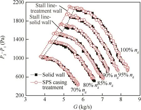
Fig.31 Effect of SPSCT-L60 on performance of TA36.25
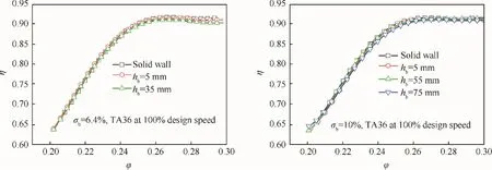
Fig.32 Effect of SPS casing treatment on efficiency of TA36.25
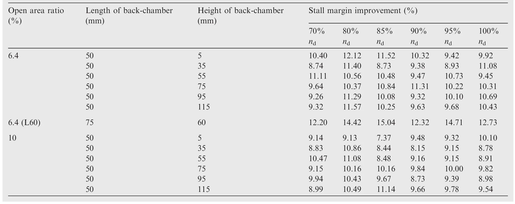
Table 1 Stall margin improvement of SPS casing treatment on TA36.25
As normally concerned,the effectiveness of SPS casing treatment might be quite sensitive to the geometry,so investigations aimed at the effect of casing geometry were also conducted. Table 125gives the results of stall margin improvement for several SPS casing treatments with different back-chambers and different perforated ratios.The rotor speed varies from 70%to 100%design speed.The smallest back-chamber height is only 5 mm,and stall margin improvement of about 8%-12%can be achieved.It should be noted that when the open area ratio is changed from 6.4%to 10%,the stall margin improvement does not increase significantly,and may even deteriorate.This means that the increase of open area ratio does not necessarily result in more stall margin enhancement.In contrast,it is possible to produce more momentum loss due to the generation of more recirculating flow.
4.1.2.Low-speed fan rig with inlet distortions
For aero-engines operating at the real circumstances,they often encounter various inlet distortions.Most inlet distortions would bring about significant detrimental effects on the compressor performance and stability.Basically,the non-uniform total pressure for inlet flows of both steady and transient patterns are considered as the most common inlet distortions.Particularly,the steady non-uniform total pressure inlet distortions can be summarized as radial distortion and circumferential distortion for their non-uniform distributions.The radial one usually induced by the growth of boundary layer in annular inlet duct,and the circumferential one is mainly caused by cross wind or take-off with large angle of attack.And the transient ones can also be categorized as rotating distortion which often exists in the multi-spool compressor,and swirl distortion which always exists for the aero-engines with S inlet ducts.The effectiveness of SPS casing treatment on TA36 with inlet distortions was also tested by Li28and Dong29et al.The stall margin improvement of SPSCT-L60 with rotating inlet distortions is shown in Fig.33.29Rotating inlet distortions were generated by rotating screens set in the inlet duct and this setup could continuously input the disturbance with particular frequency into the compressor system.In this figure,for Solid Casing case(SC)the Stall Margin(SM)decreases with the increase of the Positive(P)distortion speed,while the stall margin nearly does not change with the increase of the Negative(N)distortion speed.More importantly,the application of SPS Casing Treatment(CT cases)can obviously improve the stall margin.
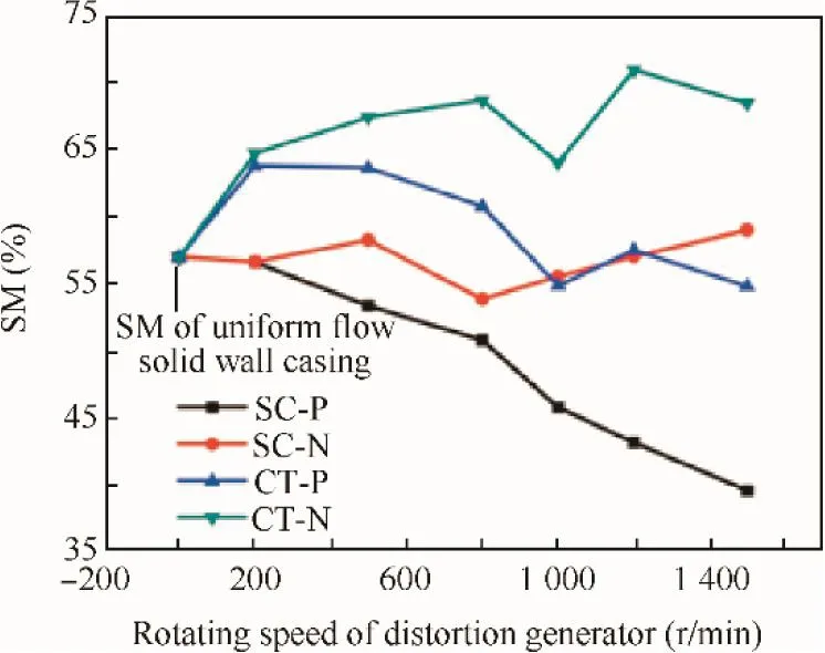
Fig.33 Stall margin improvement of SPS casing treatment with rotating inlet distortions.29
The stall margin improvement of SPS casing treatment(SPSCT-L60)with 10%circumferential inlet distortion is shown in Fig.34,42in which 10%distortion means the covered area by a distortion plate is 10%of the whole inlet area,ψ is the pressure rise coefficient,and the uniform inlet case is indicated as ‘‘UI”.From the zoom in graphs,the stall points move to the right narrowing the stability margin,and the application of SPS casing treatment can pull the stall points back to the reference point.Under 80%design speed,the stall margin loss caused by 10%inlet distortion can be reduced from 7.22%to 1.30%;under 100%design speed,the stall margin loss can be reduced from 7.09%to 0.51%.The rated efficiency results with 10%distortion are shown in Fig.35.42In this figure,the inlet distortion causes a significant peak efficiency loss,but the application of SPS casing treatment nearly does not induce additional efficiency loss.
The comparison of the SM losses for the different distorted conditions(distortion on one side and distortion on both sides)is shown in Fig.36.42It is clearly noted that these kinds of circumferential pressure distortion can make an obvious SM loss,and with the increase of the distortion degree the loss becomes larger and larger.At the same time,by applying SPS casing treatment,the SM loss can be recovered to a certain extent.But the ability of this SPS casing treatment is limited when involved with large distortion(30%),because the effects of SPS casing treatment only exist as a boundary condition for the compressor system,and it cannot influence or change the holistic internal flow structure.
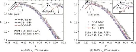
Fig.34 Characteristic curves of TA36 with SPS casing treatment(σb=6.4%)and circumferential inlet distortion.42
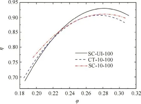
Fig.35 Efficiency curves of TA36 with SPS casing treatment(σb=6.4%)and circumferential inlet distortion.42
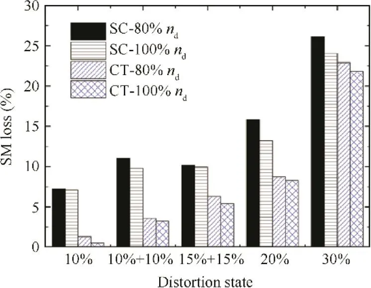
Fig.36 Stall margin improvement of SPS casing treatment with circumferential inlet distortions.42
The investigations also have dealt with the distortion of radial pattern,and relevant results are shown in Fig.37.28For this radial distortion,the inlet duct is covered by a distortion generator which is an annulus plate at the inlet casing.The covering ratio is used to represent the intensity of distortion.The 10%radial distortion case is shown in Fig.37(a),from which the SPS casing treatment not only makes up the stall margin loss caused by inlet distortion(3.11%)but also extends the stall margin by 2.57%.The 20%radial distortion case is shown in Fig.37(b),from which the SPS casing treatment can reduce the stall margin loss caused by inlet distortion from 12.05%to 2.99%.Meanwhile,efficiency results of these two conditions are shown in Fig.37(c)and(d),in which the impact of SPS casing treatment on peak efficiency is negligible.
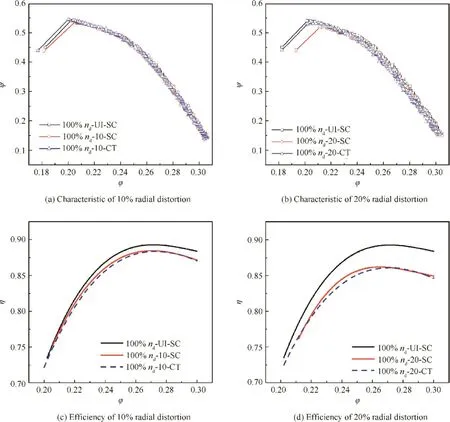
Fig.37 Effect of SPS casing treatment(σb=6.4%)on TA36 with radial inlet distortion.28
Recently,the effectiveness of SPS casing treatment subjected to swirl inlet distortion has been investigated.43Through installing a set of inlet guide vanes into the inlet duct,the swirl flow could be generated to simulate a kind of distortion caused by S duct inlet.The stagger angle is used to represent the degree of swirl distortion,for example+5 means the stagger angle of vanes is 5°and the swirl direction is the same as rotating direction of rotor.Performance results are demonstrated in Fig.3843(dPs=P2-P1),in which the test compressor are subjected+5 and+10 swirl distortion with and without SPS casing treatment.Although in these results the pressure rise curves are significantly changed by swirl flow,the stall margin nearly does not move.Meanwhile,the SPS casing treatment can improve the stall margin in different degrees under different conditions,and even can obtain some efficiency benefits.The examinations for SPS casing treatment subjected to various inlet distortions are essential.As a stabilization approach,it should be certainly effective when the stable operating range of compressor is narrowed due to inlet distortion.These existing results have well demonstrated the effectiveness of SPS casing treatment on the low-speed compressor,which can always improve the stall margin and minimize the impact on peak efficiency.
4.1.3.Two-stage low-speed compressor rig
When the compressor system becomes multi-stage,a bigger technical barrier will be showed out as the matching problem which can detrimentally affect the stability of multi-stage compressor.And with the increase of blade loading for multi-stage compressor,it is extremely difficult to meet the requirement of sufficient stall margin.Thus the flow stability problem of multi-stage compressor is the key issue for improving the holistic performance of modern aeroengine.Experimental investigations are also carried out on a two-stage axial compressor with the participating of the SPS casing treatment.The performance in compression capability and the efficiency of this two stage compressor are tested and illustrated with and without the effects of SPS casing treatment as shown in Fig.39.The results under the circumstance that the SPS casing treatment is installed at the first stage with 12%open ratio,circulararc slots,75 mm length of back-chamber and 60 mm height of back-chamber are shown in this figure.From the pressure-rise curves and the efficiency curves,it is obvious that the SPS casing treatment can enhance the stall margin without induce additional efficiency loss.But,a non-negligible fact is that the line of hollow points is little lower than the line of solid points,which means that the SPS casing treatment can cause a wispy decrease in compression capability.This decrease is a loss from that flow which participates in the recir-culating in and out the casing slots.Fortunately,the open ratio of SPS casing treatment is small enough and there is not additional significant flow loss induced.As mentioned previously,the stabilization effect of SPS casing treatment is sensitive to the open ratio which determines the system boundary impedance.So the stabilization effects of different casing conditions at 100%design working speed are also investigated,as shown in Fig.40.And in these figures the ‘‘st1” means the first stage,‘‘st2” means the second stage,and X%means that the open ratio is X%.
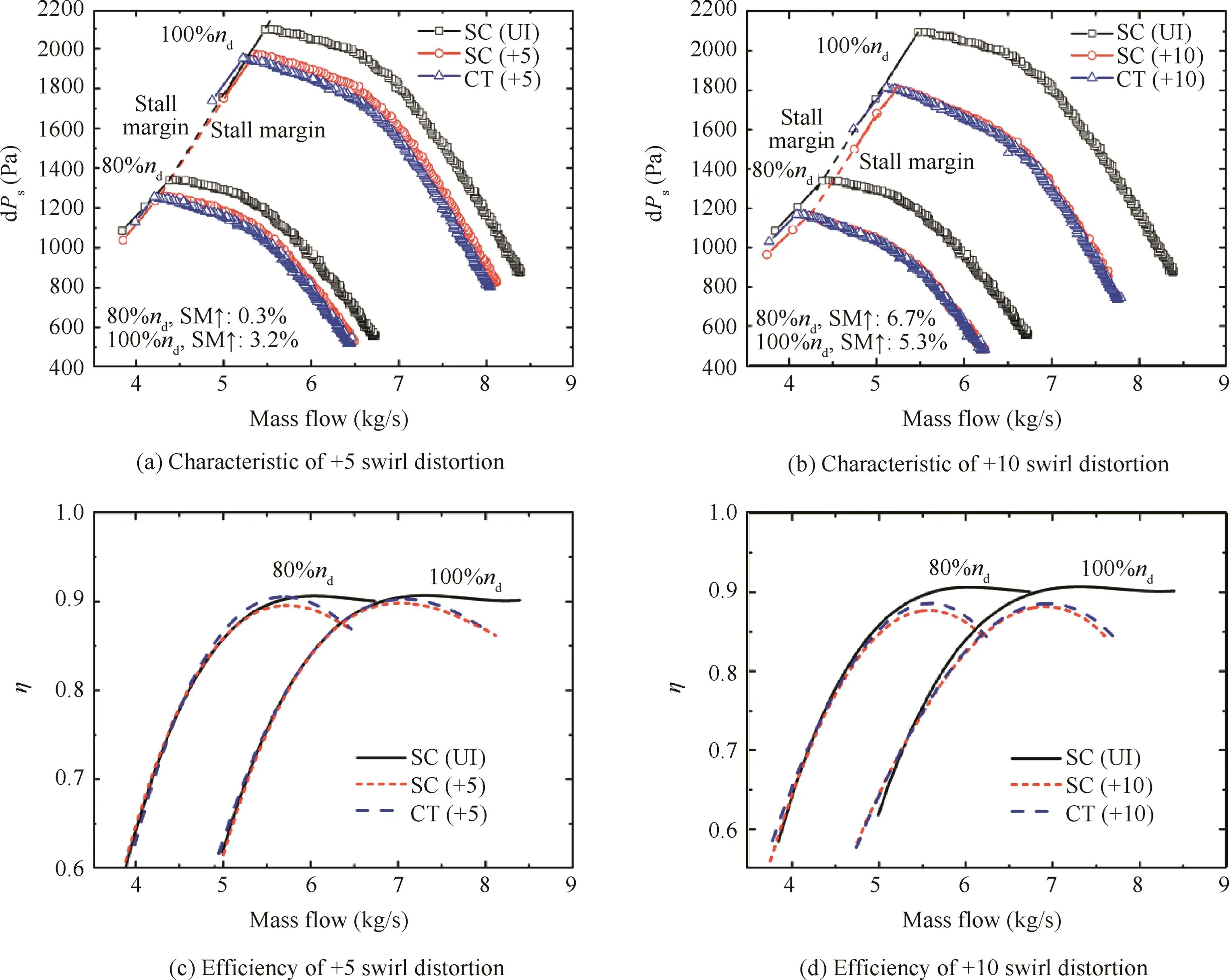
Fig.38 Effect of SPS casing treatment(σb=6.4%)on TA36 with swirl inlet distortion.43
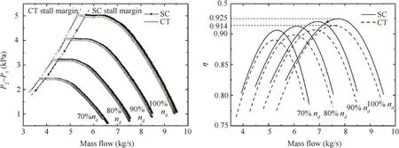
Fig.39 Effect of SPS casing treatment(σb=6.4%)on performance of TA66(four operating speeds).
Compared with the cases that the SPS casing treatment is installed at the first stage,the SM increases with the increase of open ratio,and the efficiency performances nearly do not change.And there are only a little SM benefits when SPS casing treatment is engaged in both stages because the stall precursors earlier generated at the first stage is suppressed by the casing treatment.While,the results also show that there is a tiny negative effect on SM when SPS casing treatment is only installed at the second stage.This phenomenon indicates that SPS casing treatment cannot affect the revolution of stall precursors generated at far field,which means that the main part of stall precursors is cannot infinitely spread in duct in axial direction because of the cut off condition.And the negative effect on SM may just come from the experiment error,or the specific reason might be relevant to the wispy change of compression capability of second stage caused by SPS casing treatment.Besides,from the efficiency curves,case of the lowest open ratio(CT-1)also shows the lowest peak efficiency,and the other cases seem to have the same peak efficiency.However,the error range in efficiency in this present result is about 1%,so a more proper conclusion should be that the variation of open ratio nearly does not change the compressor performance in peak efficiency.
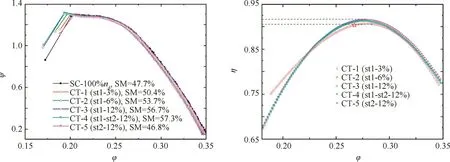
Fig.40 Effect of different casing conditions on performance of TA66.
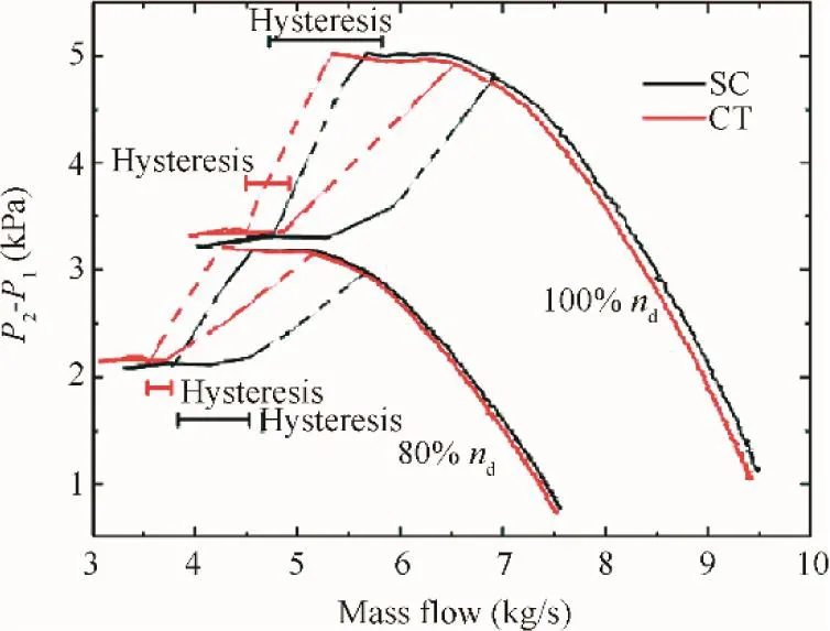
Fig.41 Effect of SPS casing treatment on post-stall behavior of TA66.
When rotating stall happens,an accepted mature solution to unstall is opening the throttle and increasing the flow rate.While,for most compressors,they require a much larger flow rate to unstall than that at which the stall first occurs.This phenomenon is usually considered as hysteresis and can be a significant problem for operating any compressor when stall might occur.The hysteresis characteristic of TA66 has also been investigated as shown in Fig.41.In this figure,the black lines represent the solid casing cases,and the red lines represent the cases with SPS casing treatment,and the solid lines are the real operating lines,while the dash lines are the virtual process.These operating lines clearly show out the hysteresis characteristic of this test compressor,and it is noted that the SPS casing treatment can significantly decrease the hysteresis process.It means that when this stabilization method is engaged,the compressor can quit the rotating stall more easily.This effect is another advantage for those aeroengine manufactures who eagerly want to put any novel stabilization method into use and gain the most benefits.The beneficial effects of SPS casing treatment exist during the pre-stall period affecting the evolution of stall precursors and still exist when stall is fully developed by accelerating the unstall process and shortening the hysteresis process.
4.1.4.Transonic compressor J69 rig
As stressed by Greitzer et al.30in their paper,the casing treatment would show the same effects on both low-speed and highs peed compressor.And generally,high-speed compressors have different aerodynamic features,which are usually more unsteady and more complex.So,it is meaningful to carry out an equal investigation on high-speed compressor for the effectiveness of SPS casing treatment.J69 is a typical transonic compressor,on which the effectiveness of SPS casing treatment has been tested.25The experimental results from 60%(high subsonic)to 96%(transonic)design rotation speed are shown in Figs.4225and 4325,in which π is the pressure ratio and REF60 indicates the reference operating point for 60%design speed as well as the REF96.It is found that the SPS casing treatment does not change the pressure-rise characteristics which follow the original slope.This means that the SPS casing treatment does not result in any obvious change of characteristics but significant stall margin enhancement.

Fig.42 Characteristics of J69 with SPS casing treatment at 60%design speed.25

Fig.44 Effect of SPS casing treatment on J69 efficiency characteristics.25
The efficiency variation for the J69 with and without the SPS casing treatment is illustrated as in Fig.4425.It can be seen that the compressor efficiency with the SPS casing treatment with lower open area ratio is even higher than that without the SPS casing treatment,which means that the SPS casing treatment can obviously improve compressor efficiency characteristics during the whole throttling process.While,with the increase of the open area ratio,the compressor efficiency will decrease because there is more recirculating flow resulting in more momentum loss.The investigations also showed that the SPS casing treatment with lower open area ratio not only results in stall margin enhancement but also improves compressor peak efficiency.This is well agreed with the expectation for a novel casing treatment.
From the results of compressor characteristics,the SPS casing treatment does not change the pressure-rise characteristics which follow the original slope.And in order to further assess the influence of SPS casing treatment on the flow structure,the spanwise distributions of the total pressure ratio have been measured with and without SPS casing treatment at three operating speeds,as shown in Fig.4527.It is believed that if the spanwise distribution is obviously changed,the SPS casing treatment seriously impacts the flow structure.And in contrast,if the spanwise distribution is not obviously changed,the SPS casing treatment does not directly influence the mean flow field.From Fig.45(a)-(c),the SPS casing treatments with small open area ratio scarcely change the spanwise distribution of the total pressure ratio at different design speed.Meanwhile,as shown in Figs.42 and 43,the SPS casing treatment can still enhance the stall margin at these circumstances although it does not significantly change the flow structures.However,if the SPS casing treatment with unsuitable geometric configurations obviously decreases the total pressure ratio,and it can be seen that the total pressure ratio along the spanwise direction will be redistributed as shown in Fig.45(d).These results can well demonstrate the effect of SPS casing treatment on the flow structure:the SPS casing treatment of proper geometry does not influence the main flow field.This phenomenon can indicate that the mechanism of SPS casing treatment does not affect the flow structure and release the blockage in the blade passages.And with the unsteady time-resolved results,the mechanism of SPS casing treatment can be explained as delaying the nonlinear amplification of stall-precursors by supplying a ‘‘soft” boundary condition or additional damping to the compressor system.This view will be discussed in detail along via existing numerical and experimental results in the next part.
4.2.Stall precursor evolution with SPS casing treatment
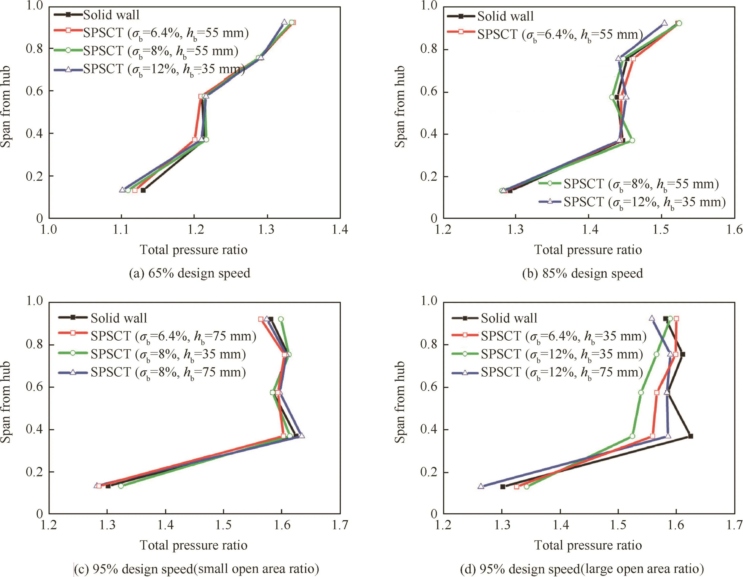
Fig.45 Spanwise distribution of total pressure ratio behind stator at near stall point of mass flow with solid wall.27
For SPS casing treatment whose stabilization mechanism is believed as suppressing the stall precursors,thus more concern has been put on the response of the dynamic system with and without SPS casing treatment.A further explanation for this mechanism will be given in this part through some relevant experimental results and detailed discussion.The configuration of SPS casing treatment is inspired by perforated acoustic liners which are often applied on civil aero-engine nacelles to absorb fan noise.After series of investigations about the interaction between perforated plate with back chamber and air flow,Jing et al.44-47found that only if the absolute velocities were equal,the inlet and outlet bias flow of micro-hole could cause the same impedance boundary condition.Meanwhile,the inlet/outlet bias flow could generate a series of vortex rings and vortex streets at the edge of perforated slots,and these vortexes would interact with pressure waves along with energy exchange.Experimental results also indicated that the energy exchange mainly was the energy transfer from pressure wave to vortex shedding.This phenomenon is called vortex pressure wave interaction(or vortex-sound interaction)which is the fundamental mechanism of the acoustic liners as well as the SPS casing treatment.
There are some relevant experimental results published in recent years,25,27-29in which the pre-stall behaviour was measured and analysed to verify the mechanism of SPS casing treatment.In these existing work,wall static pressure signals were measured by 8 pressure sensors of high-frequency response(Kulite XT-190 M),and these signals can be used to calculate the perturbation energy of pre-stall flow so as to analysis the pre-stall behavior of the test compressor with/without SPS casing treatment.The filtered time histories of the individual sensors can be used to calculate the modal information by taking a Discrete Fourier Transform(DFT)in space about the circumference of the compressor at each point in time.All the information on the wave position and amplitude is contained in the Fourier coefficients as a function of time.According to a mature power spectrum analysis method,given N measurements about the machine,the complex Fourier coefficients for each mode k are expressed by

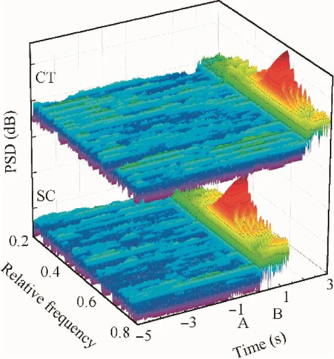
Fig.46 PSD of normalized frequency at 100%design working speed during a period of pre-stall.
where Ck(t)is the Fourier coefficient of k order,pn(t)is the pressure signal of number n sensor,N is the amount of pressure sensors,here N=8.In order to illustrate the perturbation evolution,C1(t)is used to do the process of Fast Fourier Transform(FFT)and Power Spectrum Density(PSD)which can obtain the first order energy spectrum of the perturbation.The following results are all carried out on the lowspeed fan rig(TA36)of which the design speed is 2960 r/min,and the normalized frequency is the ratio of the perturbation frequency to the shaft frequency.The PSD of the normalized frequency for the stall development process is shown in Fig.46 in terms of the comparison between SC case and CT case.In this figure,A is a near-stall point,and B is the stall point with solid casing.Hence,the flow range is equivalent for both CT and SC situations.It is obviously noted that stall of CT case is about 2 s delayed compared with the SC case,and the amplitudes of the perturbations before stall and within stall are clearly demonstrated.
In order to compare the pre-stall behaviour and the stalling behaviour respectively,two time processes are used to do the PSD analyzation,as shown in Fig.47.Fig.47(a)shows the process which starts at 2 s before the stall point of SC case and ends at the stall point of SC case;and Fig.47(b)shows the process which starts at the same start point A and ends at the first stall points of two cases respectively.During these two processes,the PSD results are shown as Figs.48 and 49.
In Fig.48,27the perturbation energy of CT case is much smaller than that of SC case,which means that the SPS casing treatment can absorb the perturbation energy in broadband.And in Fig.49,27during the stalling process,it is also obvious that the amplitude of the perturbation energy is reduced by SPS casing treatment at both stall onset and fully developed stall stages.Based on these results,it could be confirmed that the SPS casing treatment can absorb the perturbation energy in broadband in the whole stall process(from pre-stall to stall).This can directly explain the mechanism of SPS casing treatment for its ‘‘soft” boundary or additional damping effect on the compressor system.
The investigations also have been conducted subjected to different distorted inlet conditions.While,the inlet distortions usually induce significant disturbances into the compressor system,which make the amplitude of the perturbation energy become much larger than that of uniform cases,and make the comparison become unclear between SC cases and CT cases in the 3-D PSD results.So,Figs.50-5728,29,42,43show the 2-D pre-stall PSD results at different inlet conditions with and without SPS casing treatment,in which the time axes are cancelled and the power spectral densities of all time resolution steps are plotted in one moment.These figures can clearly show out the reduction of perturbation energy caused by SPS casing treatment at each condition.Such as in Figs.50 and 51,29the indicated frequency is the distortion frequency(which is determined by the rotating speed of rotating inlet distortion),and the amplitude peaks are decreased as well as the broadband perturbation energy.
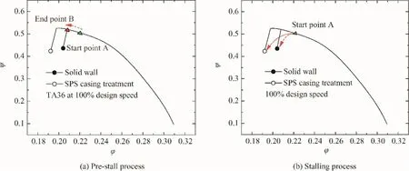
Fig.47 Time processes of PSD analyzation.
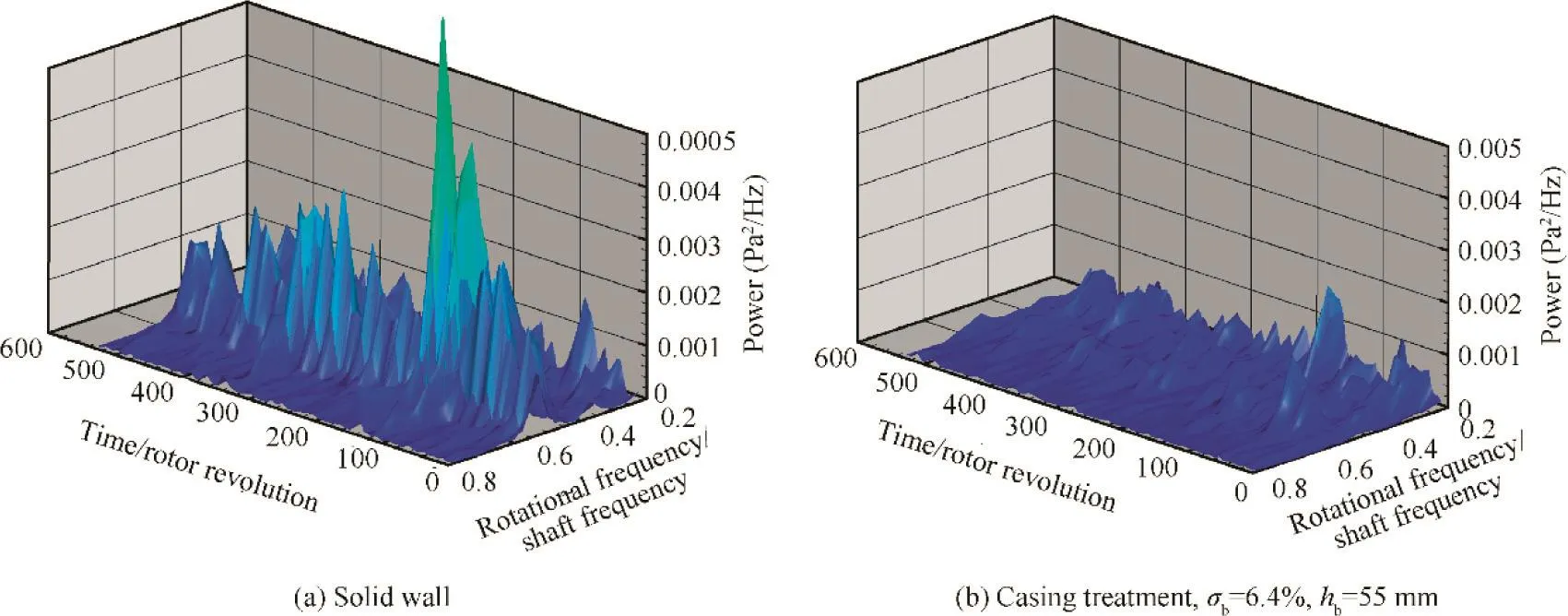
Fig.48 Comparison of PSD with and without casing treatment pre-stall at 95%design speed.27

Fig.49 Comparison of PSD with and without casing treatment stalling at 95%design speed.27
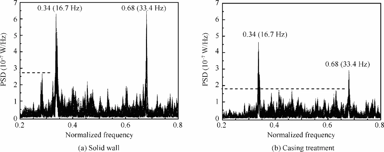
Fig.50 PSD at 100%design speed with P500 inlet distortion.29
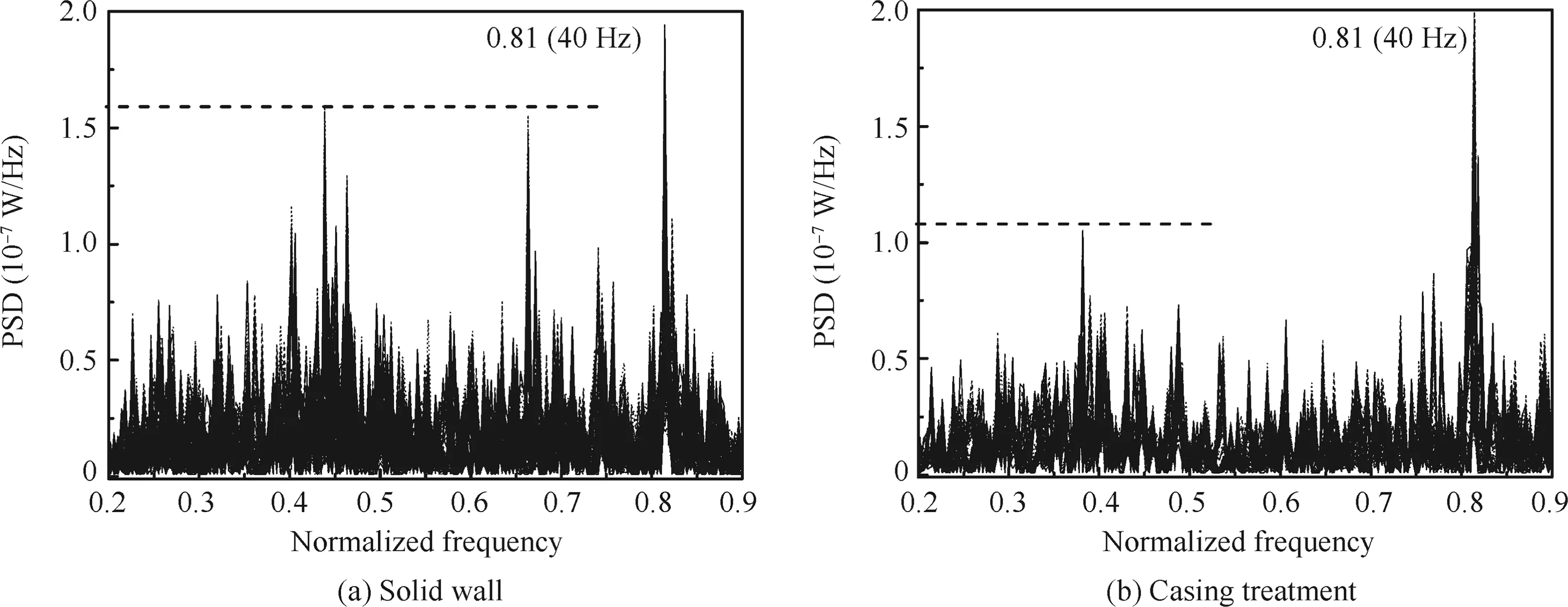
Fig.51 PSD at 100%design speed with P1200 inlet distortion.29
When the test compressor operates with the swirl inlet distortion,relevant results are shown in Figs.52 and 53.43There are swirl distortions of two directions shown in these figures,and as indicated by the horizontal dash lines,the perturbation energy is lower for CT cases.
Similar results of inlet distortions in circumferential and radial patterns are demonstrated in Figs.54-5728,42.The distortion intensities are as same as the explanation in Section 4.1,and the conclusion draw from these results is still the same:the SPS casing treatment can decrease the perturbation energy all the time,and this phenomenon proves that the SPS casing treatment can indeed provide a ‘‘soft” boundary condition as a damping to the compressor system so as to absorb the perturbation energy in flow field.

Fig.52 PSD at 100%design speed with-5 swirl inlet distortion.43
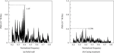
Fig.54 PSD at 100%design speed with 10%circumferential inlet distortion.42
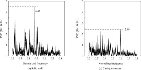
Fig.55 PSD at 100%design speed with 20%circumferential inlet distortion.42
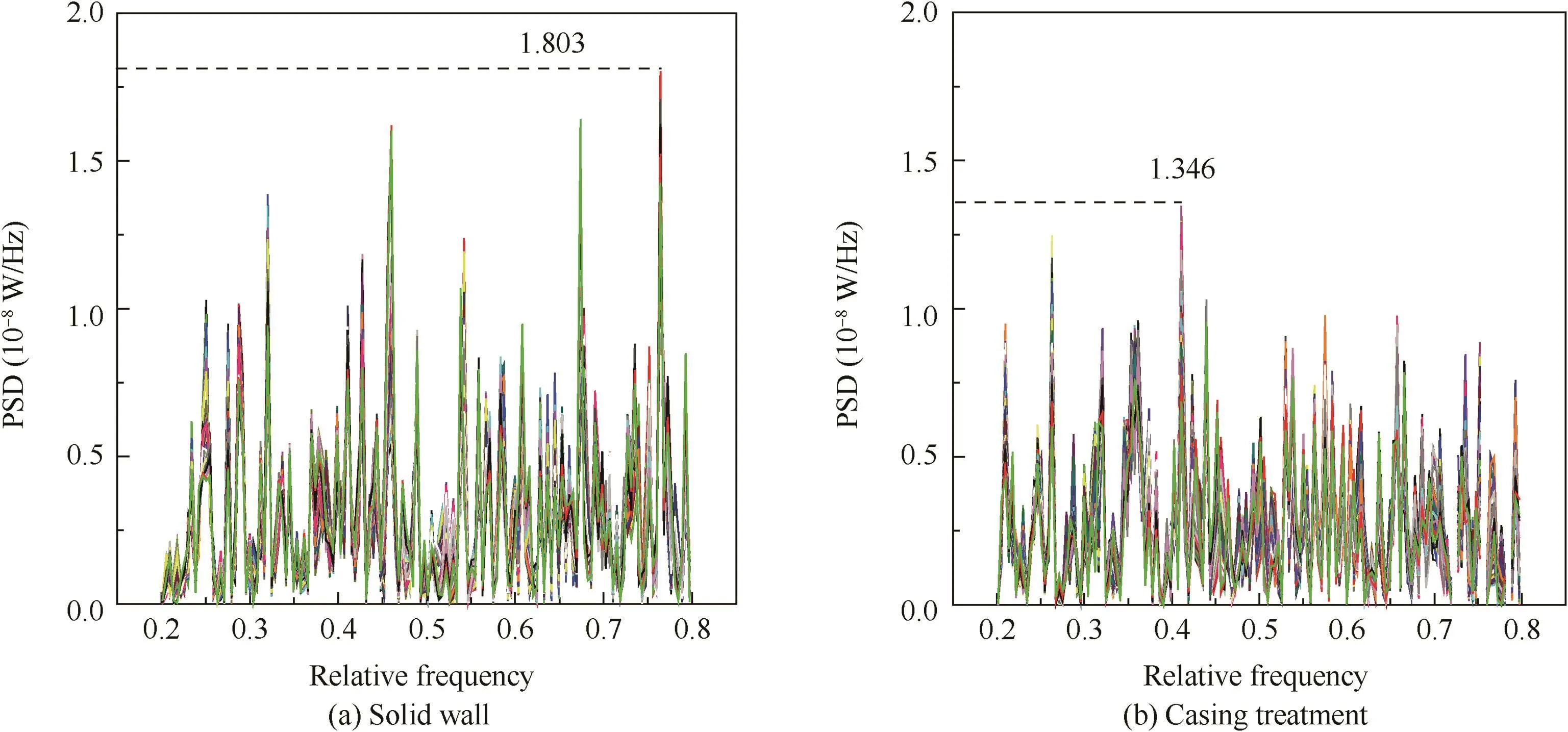
Fig.56 PSD at 100%design speed with 10%radial inlet distortion.28
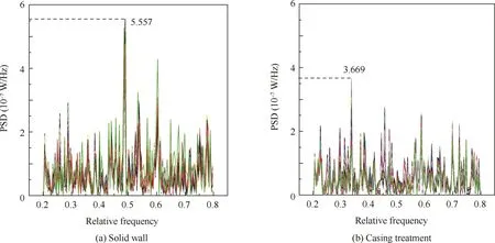
Fig.57 PSD at 100%design speed with 20%radial inlet distortion.28
Therefore,by suppressing the pressure perturbation which contains the stall precursors,SPS casing treatment can delay the nonlinear amplification of stall precursors and enhance the compressor stall margin.
5.Methodology
For a mature engineering application of casing treatment,there should be a systematic and scientific guidance approach for its design and assessment.We would like to call this guidance approach as the methodology which can guide the geometrical design and assess the performance when casing treatment is being applied.Although there is still no absolute law for casing treatment design,and most casing treatment of traditional configurations were designed through ‘‘trial and error”,there are still some assessment methods for the effectiveness of casing treatment have been developed based on computational fluid dynamic approach.Those numerical simulations which can obtain the insight into the general features of the flow structure at the blade tip region and even in the casing slots or grooves have not only explained and verified the mechanism of casing treatment but also guided the casing design by simulating various casing configurations.
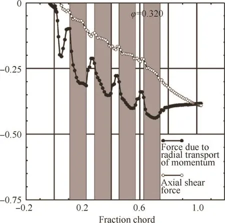
Fig.58 Evolution of cumulative sum in axial direction for axial shear force and force due to radial transport of momentum for four casing grooves configuration.50
Crook et al.48used a developed Jameson49procedure to investigate the end wall flow feature with and without grooved casing treatment numerically.In this research,the tip blockage was captured and displayed for the solid casing case,and the withdrawing and reinjecting phenomenon was simulated to induce the effect of grooved casing treatment.Compared with the experimental results,the numerical results could fully simulate the endwall flow structures for both solid casing case and treated casing case.That is to say this CFD method can be applied to pre-investigate the effectiveness of grooved casing treatment before the expensive rig test.With the further development of CFD technique,Shabbir and Adamczyk50proposed an axial momentum budget analysis which could show the fluid mechanism introduced by circumferential casing grooves at the casing over the rotor based on the regular control volume computation.Series configurations of grooved casing treatments were investigated in this research,and through this axial momentum budget analysis the contribution of each groove to stall margin improvement could be ascertained.The radial transport of momentum could be reflected in the cumulative sum for the axial shear force in the axial direction,as shown in Fig.58 of which the ordinate is the balances of the axial momentum equation.50As the authors stated in their paper,this approach could provide guidance in selecting the number of grooves required and assess the effectiveness of each groove in redistributing the radial transport of axial momentum to the power stream.For example,the relevant result showed that the five grooves casing treatment investigated in this study could be replaced by one in which the last groove was eliminated and the four grooves configuration provided the same pressure rise characteristic as the five grooves configuration.
The Shabbir and Adamczyk approach was also been applied by Legras et al.51to further investigate the mechanism of casing treatment,and through the extend Shabbir and Adamczyk approach,the effectiveness of grooved casing could be well assessed.As reviewed in the Section 3.1,Du32and Sakuma33et al.sequentially carried out the numerical simulations for the effect of grooved casing treatments and the flow structure at the blade tip region,as shown in Fig.59.In these investigations,the geometry features of grooved casing treatments were taken into consideration,such as the location,axial space and depth.Through their work,the optimal geometry could be found and assessed,which means these findings reflected from their numerical simulations could supply significant references for casing treatment designers to pre-assess the effectiveness of different designs and to improve the existing designs.

Fig.59 Geometry features of grooved casing treatment.32,33
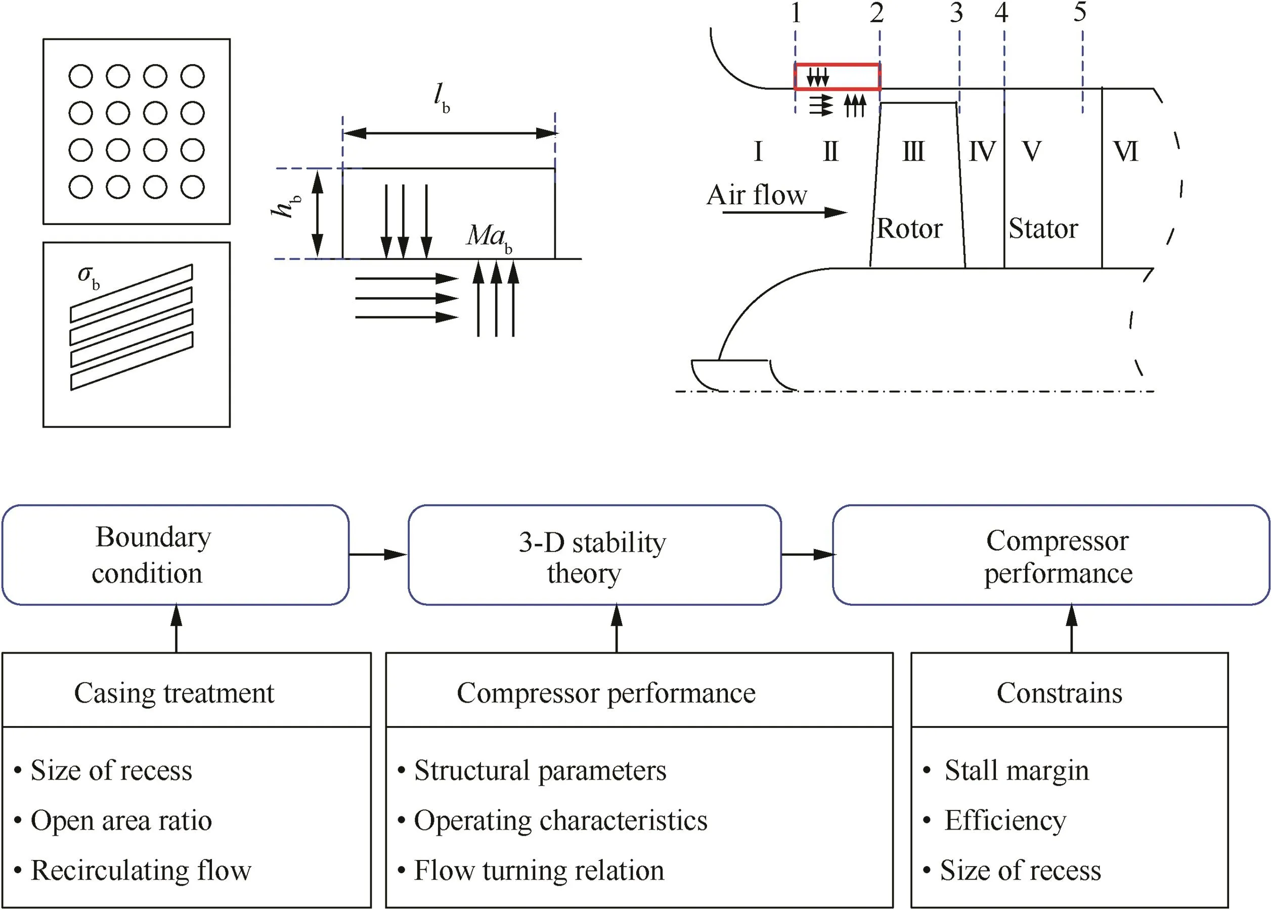
Fig.60 Road map for SPS casing treatment design.24
However,the above methodologies are mainly CFD simulations,and that is to say if we want to pre-assess or optimize the configuration design of casing treatment,we have to calculate the whole flow field for which the fast convergence and accuracy are eagerly pursued.Besides,restricted by the capability of numerical technique,all these methods only can assess the effectiveness of circumferentially grooved casing treatment by simulate the axisymmetric flow field,and for axial slotted or skewed slotted casing treatment,the CFD method become helplessly weak,let alone be applied to SPS casing treatment.As mentioned in Section 4.2,we experimentally confirmed that the mechanism of SPS casing treatment to affect the development of stall precursor waves by supplying an impedance boundary condition.Based on this understanding,we also believed that the effectiveness of SPS casing treatment on the compressor could be regarded as the influence of boundary condition on the dynamic system.And when the SPS casing treatment is considered as a boundary condition,its geometric effects could also be translated into the parameters variations of boundary condition which could be engaged in any proper compressor stability models.Based on these concerns,the design strategy for the SPS casing treatment has been developed,as shown in Fig.60,24for which the design parameters of the SPS casing treatment is determined by a study of the sensitivity of stall inception to boundary conditions under some restrictions.And then the effects of SPS casing treatment can be appropriately included in the three-dimensional stability model26,52,53as a boundary condition.Finally,through the compressor performance,the effects of SPS casing treatment can be assessed.
Through applying the equivalent surface source method,the SPS casing treatment is assumed just ahead of a compressor rotor at a negligible distance and the model for SPS casing treatment is also established.Thus,a new stability eigenvalue equation by using the continuity of pressure and velocity at both ends of the casing treatment is obtained combining the model for the casing treatment with the theoretical model to predict the stall inception of subsonic/transonic compressors,as shown in Fig.61.24In this composite model,the annular cascade was considered as a liner one with hub plate and tip,as shown in Fig.61(a)(the meanings of different variables and the matching method can be referred in Ref.24),and the casing treatment was simply assumed to be installed just ahead of a blade row at a negligible distance,as shown in Fig.61(b).
Therefore,through using the imaginary part (ωI)of the eigenvalue as a stability judgment,the compressor stability can be judged and assessed.In the model for SPS casing treatment,design parameters are extracted as open area ratio,height of back-chamber,length of back-chamber and bias flow Mach number.Results obtained on NASA stage 37,fan TA36 and J69 have shown the effects of these parameters on the compressor stability,as shown in Figs.62-64.24The results are shown in four different figures,in which one of the four parameters is adjusted while the others are kept unchanged.And it should be noted that in consideration of the actual restricting conditions of the casing treatments,the ranges of these parameters cannot be arbitrarily decided.
From the above examples,the open area ratio is a very sensitive parameter for SPS casing treatment,and for general applications,the SPS casing treatment with low open area ratio can satisfy the stabilization requirement.As mentioned in Section 3.2,low open area ratio is quite conducive to the compressor efficiency.As for height of back-chamber,results show that a larger height of back-chamber promises a more stable situation,and for different compressors,the proper values of the height of back-chamber(considering the stability and the geometric dimensioning)are also different.The effect of the length of back-chamber is seems similar to the effect of the height of back-chamber.And for the bias flow Mach number,the trends are different,but a common thing is that the bias flow with large speed is always combined with more intense vortex shedding.Based on the vortex-pressure wave interaction theory,more additional damping can be obtained through the enhanced interaction between vortex shedding and pressure wave,and the compressor system would be more stable.
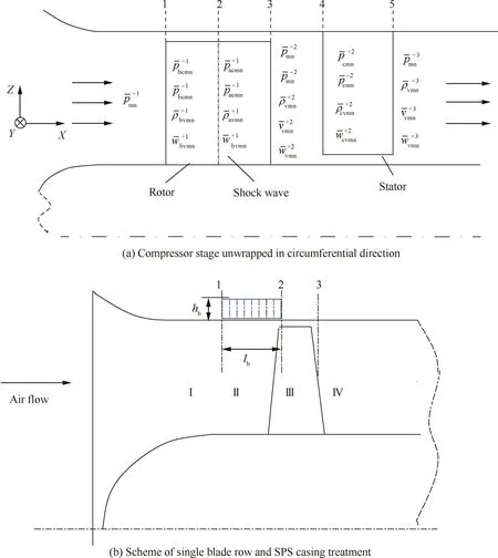
Fig.61 Compressor model with SPS casing treatment.24
This extend 3-D compressor stability model combined with the effects of SPS casing treatment is a successful methodology for the design of SPS casing treatment.Through this method,the most sensitive parameter can be captured and the optimal geometric configuration can be also obtained.Unlike those methods based on CFD simulations,the eigenvalue approach is more efficient,and it can directly supply the effect trends of different design parameters as a guiding opinion.
6.Further discussion
6.1.Casing treatments and the inception of rotating stall
It is easier to describe and explain the effects of casing treatments when they are significantly affecting the endwall flow structure.While for a hydrodynamic system,the affect on the flow structure can also cause the variation on the system response,which is usually reflected from the pattern and evolution of stall inception waves.Based on the initial investigations(McDougall et al.,54Garnier et al.55and Day56),the stall inception waves have been regarded as circumferentially active perturbations,and generally defined as two types for the different wave scales:short scale ‘‘spike” type and long scale ‘‘modal wave”type.And the form of stall inception is the combination result of many comprehensive factors such as blade shape,aerodynamic loading,tip clearance and even casing condition.Through the spatial structure analyses,the circumferentially travelling wave could be well captured and demonstrated.55,57,58For the sake of applying active stability control,the modal wave stall inception has become the most anticipated stall initiate.However,for a long time,casing treatment technique as a typical passive stabilization approach has not been connected with the investigations about the stall inceptions.58,59In these very few attempts,Gorrell and Russler58found that a kind of recirculating cavity casing treatment could bring about circumferential action mode at the rotating stall initiation,and they confirmed that it was the modal wave stall inception.As shown in Fig.65,58the pressure traces in time domain clearly shows the travelling circumferential waves(indicated by the red line),and the SFT(Spatial Fourier Transform)phase result contains three wave modes in which the dominated one(Mode 1)shows the circumferentially travelling speed and the speed conversion phenomenon.The rotating stall onset is 71%shaft frequency and the fully developed stall is 53%shaft frequency.The only reason for the present of modal wave is associated with the recirculating cavity which has connected every casing slot as well as every blade passages.
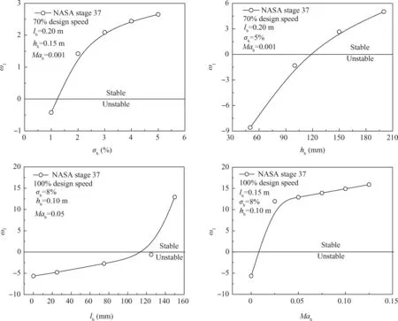
Fig.62 Effects of CT parameters on compressor stability,NASA stage 37,mode number(1,1).24
The time-resolved results have also indicated the significant effect of SPS casing treatment on the stall inception of this test two-stage low-speed compressor.This two-stage compressor engaged in this research is also a typical spike one,of which the stall evolutions with different casing conditions and two working speeds are demonstrated in Figs.66 and 67.In Fig.66(a),there is an indicated spike type stall inception which is 0.2 s before the detectable stall onset,and then the stall onset develops into the fully developed rotating stall as indicated.While unexpectedly,the case with SPS casing treatment shows an obvious circumferential perturbation wave before the stall onset,as shown in Fig.66(b).The detectable wave transporting circumferentially is believed as a modal wave stall inception.When the operating speed is 100%design speed,the solid casing case still shows spike type stall inception,and the application of SPS casing treatment can convert the stall inception into the type with circumferential action,as shown in Fig.67.
This phenomenon was also found by Houghton and Day10when they investigated the effects of circumferentially grooved casing treatment concentrating on the inception mechanism and solidity.The common feature for circumferentially grooved casing treatment and the SPS casing treatment is that they both contain a circumferentially communicated cavity,the grooved cavity and the annular back-chamber,which can not only supply a bypass for endwall flow but also can enhance the perturbation of circumferential mode.For SPS casing treatment,the local disturbance(as well as the spike stall inception)could be absorbed by the vortex-pressure wave interaction,but the energy of the disturbance would exist for a while and become a circumferential action when approaching the rotating stall.This convert could be considered as a circumferential redistribution for blade loading,which means the effectiveness of SPS casing treatment(maybe other circumferentially grooved ones)is firstly based on the vortex-pressure wave interaction which can affect and absorb the stall precursor,and then the circumferentially communicated cavity can supply an additional system damping by converting the radial disturbance into a circumferential one,which can significantly increase the attenuation time through a longer attenuation distance.
6.2.Insufficiency of casing treatment

Fig.63 Effects of CT parameters on compressor stability,fan TA36,mode number(1,1).24
Although there are many successful applications of casing treatments carried out by manufacturers,this technique is still a developing one of which the insufficiency and prospect should be of great concern.The biggest problem is how to properly design the configurations targeting at different rotor types.While,as mentioned in the Section 3.1,an optimistic fact is that those configurations which have a substantial effect on stall margin at low-speed stages also have a substantial effect at high-speed stages.A proper design is quite related to the sufficient and correct understanding for the stabilization mechanism of casing treatment.The existing investigations have pointed out that for traditional configurations,the injecting and withdrawing flow at the edge of slots supplies the necessary momentum exchange between healthy flow and unhealthy flow,and for SPS casing treatment,the vortexpressure wave interaction and communicated back chamber constitute the additional system damping for suppressing the stall precursors.But these understanding for the stabilization mechanism have not been connected with the rotor aerodynamic design,which means one has to cater to the aerodynamics to carry out proper casing configuration rather than conduct a combination design to optimize the endwall flow.Another disadvantage for casing treatment is the additional weight for the extra configuration,and weight is a strictly controlled factor for any flight vehicles.So a promising option is to combine casing treatment with some other technique such as the acoustic liners,and the combination can save weight and space both.
7.Summary and conclusions
Casing treatment technique as a typical stabilization approach,whose effectiveness is undoubted,has been verified by numerous successful applications.With investigating the phenomenon of compressor instability increasingly,the understanding for the stabilization mechanism of casing treatment has been unprecedentedly deep and comprehensive.Besides the casing treatments of regular configurations,novel design such as SPS casing treatment has also shown remarkable stabilization capability based on the new aspect for its mechanism.It is worth noting that SPS casing treatment originates from a totally different perspective about the compressor instability with regard to the traditional casing treatments.It plays as a passive stabilization role in the compressor system,but it can affect the dynamic evolution process of the stall precursor waves.This fact also determines that this novel design can avoid the most insufficiencies usually induced by traditional casing treatments,such as the decrease of compression capability and overall efficiency.While,for all these reviewed investigations,the most general features about casing treatment can be summarized as follows:
(1)The most commonly applied configurations for casing treatment are axial slotted,skewed slotted and circumferential grooved.
(2)Nearly all the efficient casing treatments can improve the compressor stability but with efficiency loss as penalty.While a proper design aimed at particular compressor can realize a minimum efficiency loss.
(3)Besides axial compressor,casing treatment technique can also be applied on centrifugal compressor at the shroud of inducer or diffuser to extend the stability margin.
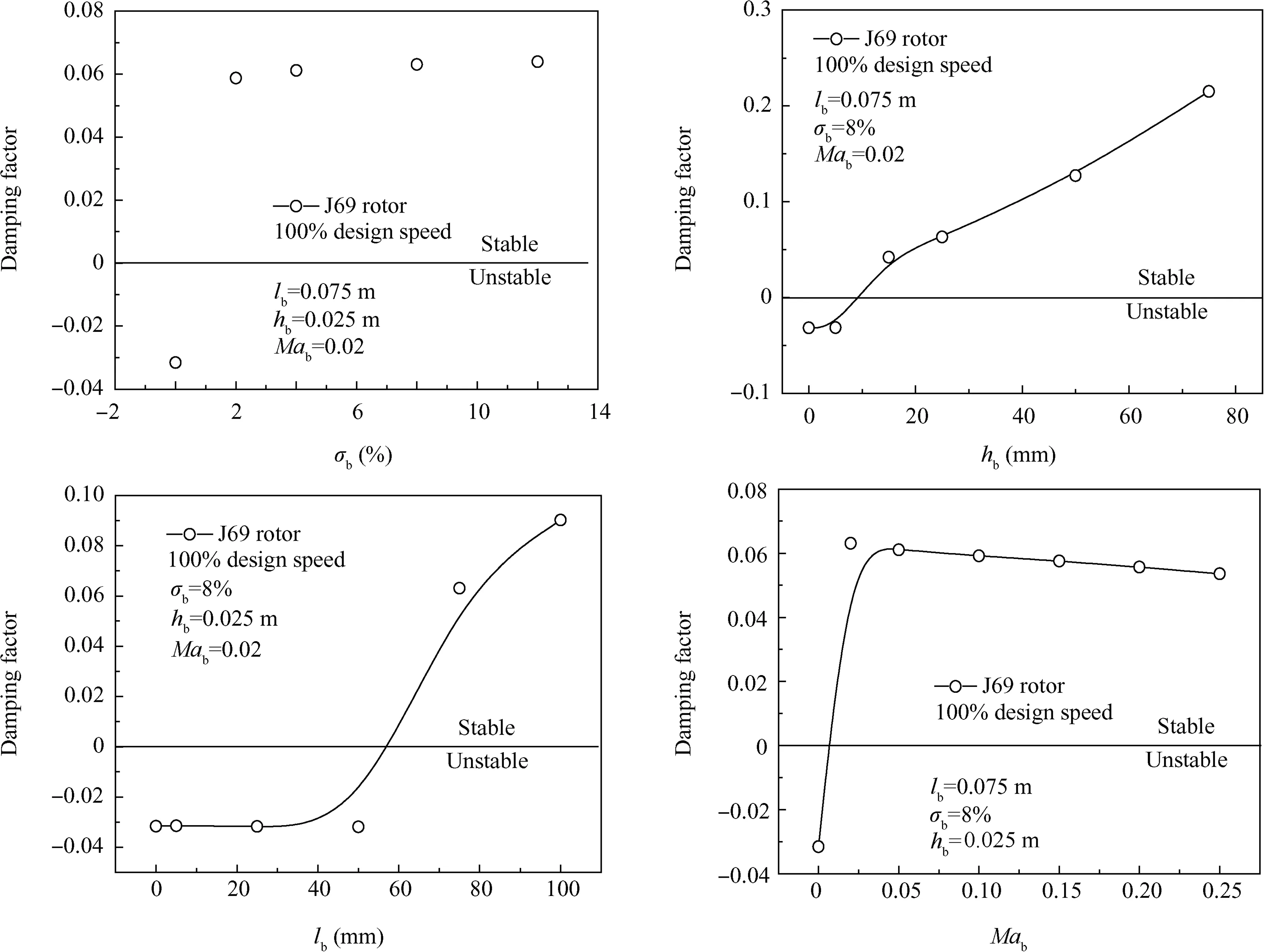
Fig.64 Effect of CT parameters on compressor stability,transonic J69,mode number(1,1).24
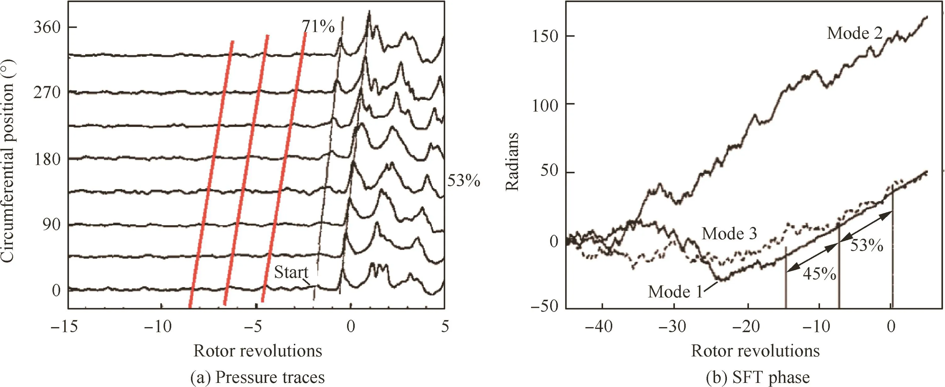
Fig.65 85%speed with recirculating cavity casing treatment.58
(4)For casing treatments of regular configurations,the main aspects of the reason for stability improvement are removal of low energy fluid from the high loading part on blade and release of the flow blockage via the additional flow path and with drawing-re injecting flow supplied by treated casing.
(5)Casing treatment not only changes the compressor steady performance,but also the stall inception.The circumferential grooved casing treatment has significant influence on stall inception which could be converted from a short-length local mode into a long-length circumferential mode.
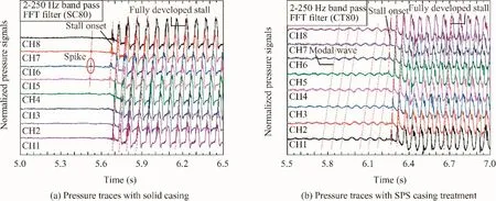
Fig.66 Pressure traces of stall evolution at 80%design speed.
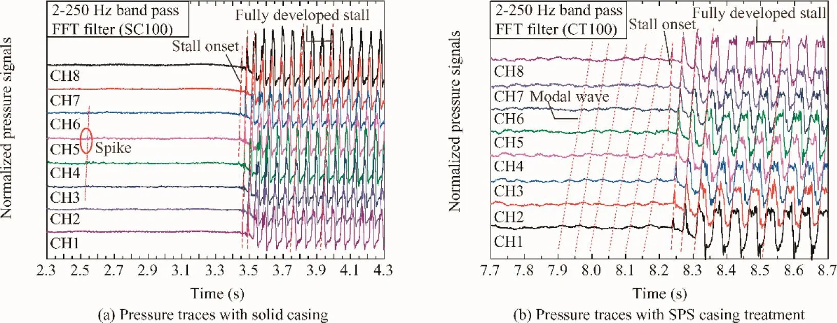
Fig.67 Pressure traces of stall evolution at 100%design speed.
(6)A SPS casing treatment has been well developed,which shows remarkable effectiveness on stability improvement.The most outstanding features of this novel casing treatment are its simple configuration and low(nearly no)efficiency penalty.(7)The mechanism of SPS casing treatment is associated with the interaction between shedding vortexes and pressure waves on casing boundary,which can suppress the nonlinear amplification of compressor stall precursor and therefore improve its stability.
(8)There are many methods to pre-assess the effectiveness and guide the design of casing treatment,and most are CFD simulations for circumferential grooved configurations.Through these methods,the flow structures with the presence of casing treatment can be obtained as well as the assessment for the effectiveness of different configurations.
(9)An extended 3-D compressor stability model combined with the effects of SPS casing treatment can successfully guide the design of SPS casing treatment by obtaining the most sensitive parameters and the optimal geometric configuration.
Finally,considering the rapid development of aero-engines,there must be higher requirement for compressor stability in the future.We should not be stalled on the way of exploring the technique of casing treatment just like the operating compressor should not be stalled with the presence of casing treatment.
Acknowledgments
The research presented here is supported by the National Natural Science Foundation of China(Nos.51790514,11661141020 and 51576008).
杂志排行
CHINESE JOURNAL OF AERONAUTICS的其它文章
- Recent advances in physical understanding and quantitative prediction of impinging-jet dynamics and atomization
- General aspects on structural integrity
- Design and simulation of an innovative cylinder fabricated by selective laser melting
- Application of reliability technologies in civil aviation:Lessons learnt and perspectives
- FEC design for remote control and data transmission of aeronautic and astronautic vehicles
- Performance limitations in trajectory tracking control for air-breathing hypersonic vehicles
