Design and simulation of an innovative cylinder fabricated by selective laser melting
2019-01-16GuangMENGBinJIHanHANChengzhangGURenbangLINFujunPENG
Guang MENG,Bin JI,Han HAN,Chengzhang GU,Renbang LIN,Fujun PENG
aShanghai Academy of Spacelight Technology,Shanghai 201109,China
bShanghai Key Laboratory of Spacecraft Mechanism,Shanghai 201109,China
cAerospace System Engineering Shanghai,Shanghai 201109,China
KEYWORDS Axial compression;Cylinder;Failure;Imperfection;Lattice sandwich structure;Selective laser melting
Abstract Additive Manufacturing(AM)processing has attracted wide attention due to its advantages,e.g.,rapid prototyping and free design.In aeronautic and astronautic engineering,it is especially attractive to apply AM processing,especially Selective Laser Melting(SLM),into primary structures that always occupy most of the whole mass of aircraft or spacecraft.In this paper,an innovative lattice sandwich structure that is suitable to be manufactured with SLM is adopted to design the typical cylinder under axial compression.Firstly,the mechanical properties of pyramidal lattice are investigated,and the bearing capacity of the lattice sandwich cylinder is given analytically for each failure mode.Secondly,a composite cylinder is re-designed in the form of lattice sandwich structure,which sizes are ultimately obtained through optimization.Finally, finite element model of the innovative cylinder is established and several kinds of imperfection are introduced to simulate the defects caused by SLM.Numerical result shows that the lattice sandwich design can obviously enhance the bearing capacity of cylindrical shell even though the original one is designed with composite material.In other words,SLM has great potential in improving the primary structure of spacecraft in the future.
1.Introduction
Additive Manufacturing(AM)technology is a novel and advanced processing methodology that appeared in the 1990s.Defined as ‘‘process of joining materials to make parts from 3D model data,usually layer upon layer,as opposed to subtractive manufacturing and formative manufacturing methodologies”by the International Organization for Standardization (ISO)/American Society for Testing and Materials(ASTM)52900:2015 standard,AM technology has many advantages,such as schedule and cost savings,part count reductions and suitability for complex structures,and therefore has caused wide concern in engineering.
Operated in multi-stages including ground transportation,launch stage and orbit stage,most space structures are subjected to many types of loads,such as quasi-static force,heat and vibration,and therefore require complicated configuration.Moreover,many space structures represent small batch and low-rate production.All of these features make them suitable to be fabricated by AM processing.
The most common AM technology for metal material can be divided into two kinds.One kind is directed energy deposition process such as Laser Engineered Net Shaping(LENS),1and another is powder bed fusion processes such as Selective Laser Melting(SLM).2,3Compared with the former one,powder bed fusion processes can fabricate the product with high precision and need less surface treatment.Many kinds of space structures have already been fabricated by SLM processing,4such as engine or satellite bracket.
In fact,the primary structure takes up most of the dry weight of the whole spacecraft.Therefore,it would be very attractive if the weight of primary structures can be reduced through combining AM processing and the novel design.Although there are some constraints for this processing at present,such as the size limits in SLM methods,they may be eliminated with the rapid development.However,there has been little study on the primary structures fabricated by SLM processing in spacecraft.
As a stretch-dominated material,lattice material has many advantages,such as high strength and high stiffness to density ratio.5,6Many researchers have adopted lattice material to fabricate various sandwich cylinders,including pyramid lattice sandwich cylinders7-9and Kagome lattice sandwich cylinder.10However,all of these cylinders are fabricated with traditional processing,instead of AM processing.Some researchers have also begun to design other structures involved with lattice material in recent years.Taken the three-point bending specimen as an example,Daynes et al.11applied a novel isostatic line method in designing the functionally-graded lattice core.Mahshid et al.12adopted SLM method to fabricate cylinders of 28 mm diameter and 46 mm height based on four architectures—solid,hollow,lattice structure and rotated lattice structure.Compared with the hollow one,the cylinder with lattice structure can carry 10%more load.Combining topology optimization and AM processing,Richards and Liu13devised the lattice-reinforced penetrative warheads with some internal stiffeners and micro-lattice.Walker et al.14redesigned the wing from a Van’s RV-4 homebuilt aircraft in several different forms.When adopting lattice sandwich design,the performance was greatly enhanced even though the mass was significantly increased.In this paper,a novel lattice sandwich design is attempted to applied in a primary structure of spacecraft,which is suitable to be fabricated by SLM methods.Some key points including the effects of imperfections are analyzed,and the advantage of this innovative design is highlighted by comparison with the initial Carbon Fiber Reinforced Polymer(CFRP)cylinder.
2.Design and experimental result of initial CFRP cylinder
In this section,a CFRP cabin in a spacecraft are introduced as shown in Fig.1.It is an anisogrid stiffened composite cylinder with the upper and bottom frames,the skin and the Kagome stiffeners,all of which are integrated on a mandrel and cocured in an autoclave by the filament winding process.The upper and bottom frames have 490 mm and 504 mm outer diameters,and 490 mm and 470 mm inner diameters,respectively;the whole height isH=310 mm;the inner diameter of the cylinder isR=486 mm.The practical specimen weighs 5.5 kg.
During the progress of the experiment,the specimen is placed on a steel support base,with 24 steel M6 bolts connected with the bottom frame.Its upper frame is connected with a steel cap through 24 steel M6 bolts.The axial displacement is measured through 4 sensors on the upper frame,each per quadrant.Axial compression load is slowly applied to the steel cap by means of a universal hydraulic testing machine,being set 20 kN as an increment.When it reaches about 400 kN,there is a clear turn point in the force-displacement curve(see Fig.2),which shows that the cylinder has some obvious damage.This value should be identified as the limit load due to the great reduction of the stiffness.However,the shell can continuously carry the load.The cylinder is eventually destroyed at 469.5 kN with a loud sound.Fig.3 gives its failure mode,which appears in the second axial Kagome grid.
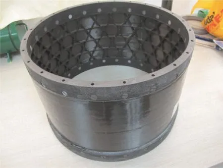
Fig.1 CFRP cylinder specimen.
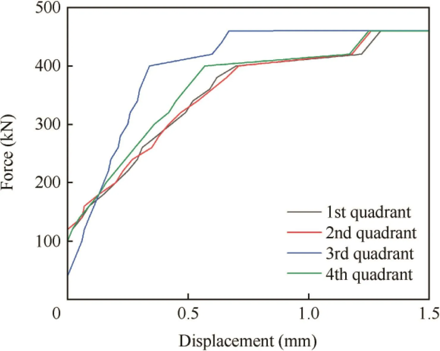
Fig.2 Force vs axial displacement curves for upper frame of CFRP cylinder.
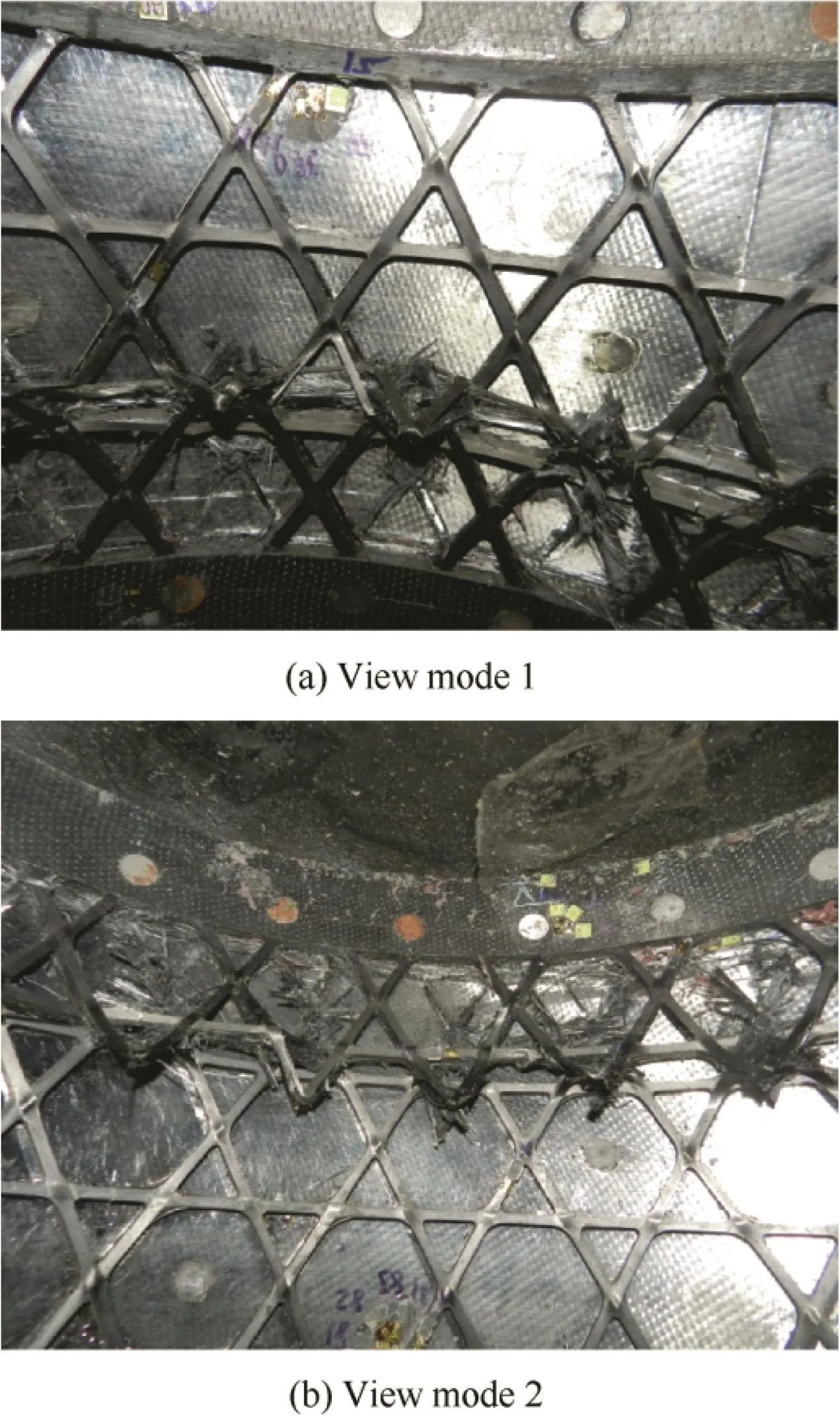
Fig.3 Failure modes of CFRP cylinder.
3.Innovative design of lattice sandwich cylinder
Under the same height 310 mm and internal radius 486 mm as in Section 2,the cylinder would be redesigned as an innovative lattice sandwich shell with the pyramidal core in this section.
3.1.Mechanical properties of pyramidal lattice core
The mechanical properties of a generalized lattice core cell are firstly introduced,as shown in Fig.4.The bottom face of the cell has unequal length and width.The strut in the lattice cell has the circle cross-section with radiusrand the lengthl/nz,wherenzis the number of cells in normal direction of the lattice core.The inclination angle between the strut and the bottom plane is ω,and the angle between the diagonal and the longitudinal direction of the bottom plane is α.Moreover,the elastic modulus,the Possion’s ratio and the yield strength of the solid of which the lattice is made areEs,μsand σs,respectively.
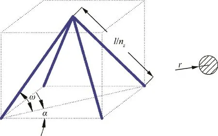
Fig.4 Pyramidal lattice cell.
The relative density of the pyramidal lattice is related to the cell geometry via

The equivalent elastic modulus of the lattice is

The equivalent out-of-plane shear modulus of the pyramidal lattice can be deduced from the deformation compatibility principle

where the subscript‘‘13” and ‘‘23” represent the 13-component and 23-component of transverse shear stresses,respectively.In this paper,only the 13-component of transverse shear stress is used for the lattice core because of the direction of compression load,and it can be rewritten as

The interval of the adjacent points in the struts along the axial directionlccan be expressed as follows for the pyramid lattice cell

3.2.Bearing capability of lattice sandwich cylinder
The primary structure of spacecraft is mainly subjected to moments and axial force,both of which can be simplified into the equivalent axial compression.Many researchers have studied failure behavior of the sandwich cylinder with the honeycomb core15or foam core.16However,the8re is few research on the lattice sandwich cylinder.Xiong et al.adopted an interlocking fabrication technique to manufacture a CFRP cylinder with aluminum pyramidal lattice core,and made an axial compression experiment.They gave several failure modes in analytical form including Euler buckling,shell buckling,skin dimpling and skin crushing.Based on this work,the more comprehensive failure modes are given in this section including five forms as shown in Fig.5.
3.2.1.Euler buckling
Euler buckling would appear when the length of the cylinderHgreatly exceeds its radiusR,that isH>>R.The bearing capability can be obtained from

wherekeis the coefficient that depends on the up and bottom boundary condition,and can be conservatively assumed to beke=1;Dis the bending stiffness of sandwich cylinder,which can be divided into three part,that of the outer skinDf1,that of the inner skinDf2and that of the lattice coreDc.


Fig.5 Failure modes of lattice sandwich cylinder.
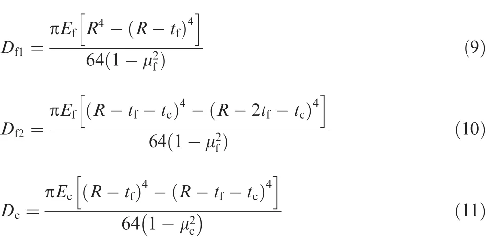
wheretfandtcare the thickness of the skins and the lattice core,respectively;EfandEcare their elastic modulus;μfand μcare their Poisson’s radio.
3.2.2.Macro buckling
For a sandwich cylinder,when the skins have much larger stiffness than the core,the bearing capability can be obtained through

wherekmis the coefficient that needs to be confirmed by the test data.In this paper,it is referred as that of the foam,i.e.,km=0.7.
3.2.3.Skin wrinkling
For the sandwich structure with the isotropic skin,when the core is much thicker than the skin,the skin may wrinkle due to the compressive stress

wherekwis the coefficient that is obtained as 0.78 by Allen,170.825 by Plantema18and 0.91 by Hoff and Mautner19;EfandEcare the elastic modulus of skins and lattice core in the normal direction.
Ignoring the axial force in the lattice core,the bearing capability of the sandwich cylinder can be expressed as

3.2.4.Skin dimpling
If the interval of the adjacent points along the axial direction are large enough,the skins can easily dimple.The bearing capability of the sandwich cylinder can be calculated by

wherekdis the coefficient that depends on the supporting condition,andkd=1 is chosen in this section.
3.2.5.Skin yield
When the skin stress reaches the yield strength,the cylinder is conservatively considered to be destroyed,and the bearing capability can be easily obtained as

3.3.Optimized design
The mathematic model of the optimization problem for lattice sandwich cylinder can be expressed as

where x is the vector of all the optimization variables;xlband xubare the lower and upper limits of the optimization variables;P0is the constraint of the bearing capability.Considering the possible errors between theoretical and practical specimen,the constraint of the bearing capability is set to a bit higher than the experiment result 469.5 kN,that is,P0=700 kN.Finally,the optimal variables are solved as listed in Table 1 through a simple exhaustive method,whereNRowandNColare the numbers of lattice cell along the axial and circumferential direction.The main body of the innovative cylinder only weighs 2.95 kg.If the frame has 5 mm thickness and 30 mm width,both of them weighs 1.28 kg.The whole mass is 4.13 kg,only 75%of the initial CFRP cylinder.

Table 1 Results by optimized design.
4.Imperfections brought by SLM processing
In this section,a practical product is used to investigate the imperfections caused by SLM processing.It is the sandwich plate specimen with pyramid lattice core,and two samples are fabricated using EOSINI M280 machine.The raw material is AlSi10Mg,and its elastic modulus isEs=(65±5)GPa,yield strength is σs=(220 ± 10)MPa,failure strength is σb=(325 ± 20)MPa and failure strain is εs=0.07 ± 0.02.According to technical index provided by EOS company,the surface roughness isRa=6-10 μm andRz=30-40 μm.
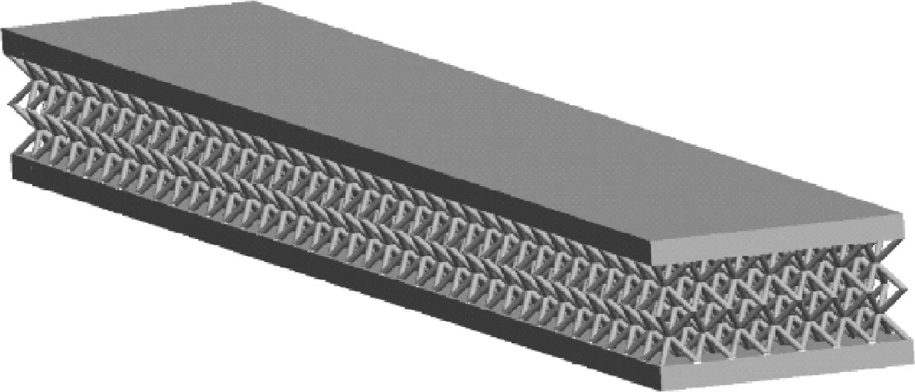
Fig.6 CAD model of lattice sandwich specimen.
The CAD model of the specimen is shown in Fig.6 and their sizes are given in Table 2.Fig.7 shows additive manufacturing direction and Fig.8 gives the local enlarged photographs of both sides of the struts.Obviously,the imperfections in the back side of the struts are more visible than those in the front side due to lack of the supports of powers during fabricating.Fig.9 gives the metallographic photographs of both skins and lattice core.The imperfections can be ignored for the skins because they are much smaller than the thickness,however,they should be considered for the struts in respect that the largest imperfection is about 0.1 mm and may affect the slender struts with the radius 0.4 mm.
Defined as Eq.(18),the relative deviation is used to estimate the stability of SLM processing,i.e.,

where δxis the relative deviation;xiis theith test value;x-is the average value.The weight of two samples is 170.86 g and 170.65 g,and its relative deviation is 0.06%.The high consistence shows that AM processing is effective to fabricate the high-quality specimens.

Table 2 Specimen sizes for lattice sandwich plate.

Fig.7 Scheme of additive manufacturing direction.
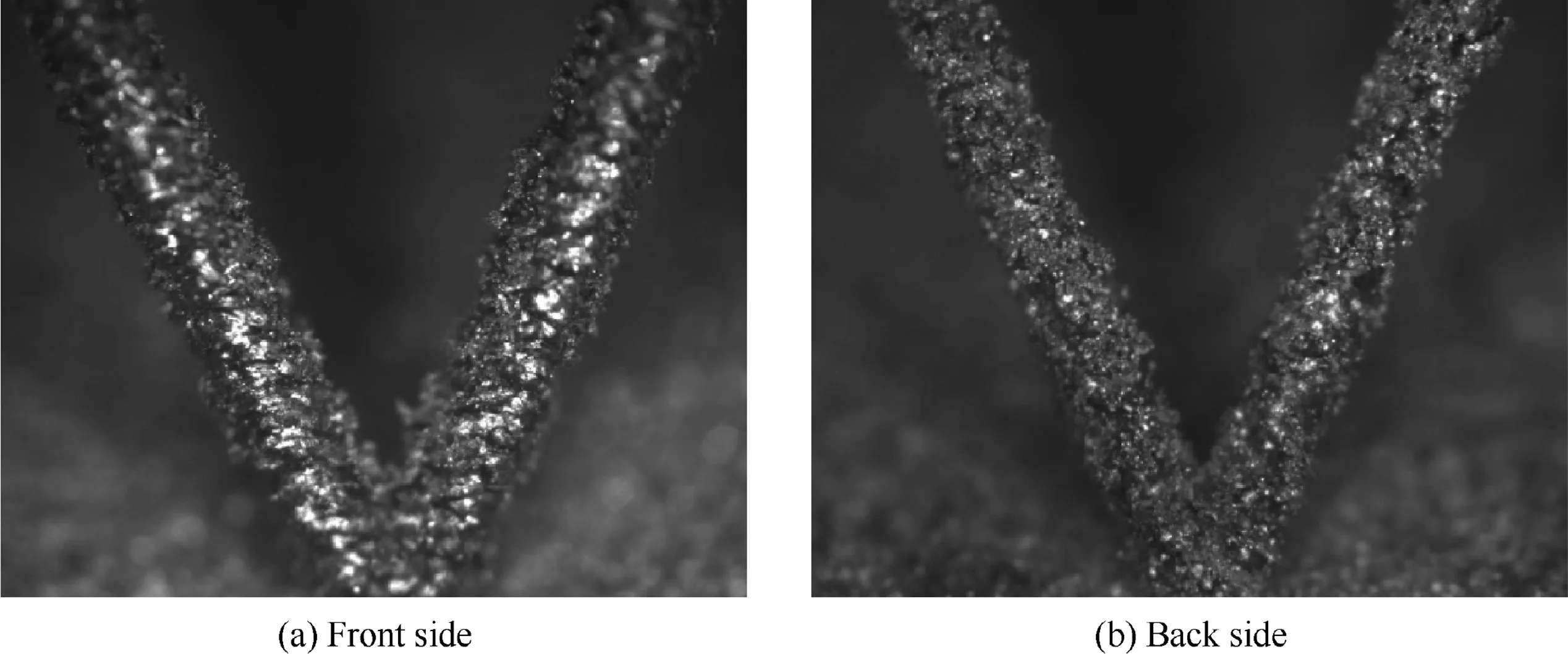
Fig.8 Local photographs of lattice sandwich specimen.
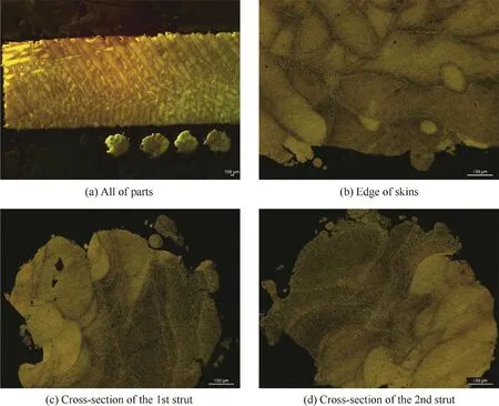
Fig.9 Metallographic photographs of lattice sandwich specimen.

Fig.10 Typical imperfections in lattice sandwich structures fabricate by SLM processing.
According to the observation from the specimen,two types of imperfections may be brought by SLM processing,including the skin’s thickness imperfection and the strut’s radius imperfection,as shown in Figs.10(a)and(b).In addition,the non-planarity of the skin can lead to the shape imperfection,as shown in Fig.10(c).In conclusion,these three kinds of imperfections are the common ones caused by SLM methods.
5.Finite element analysis
In this section, finite element method is applied to simulate mechanical behavior of the lattice sandwich cylinder fabricated by SLM method.However,the applicability of finite element method need to be firstly verified based on some simple tests,such as the in-plane compression test of the lattice sandwich plate.
5.1.Applicability of finite element method in lattice sandwich plate
The specimens in Section 4 are chosen to implement the inplane compression test where the load is forced on along its longitudinal direction.For the two samples,the bearing capacity is 48.79 kN and 47.98 kN,and its relative deviation is only 0.83%.The load process is shown in Fig.11.
The commercial software ABAQUS is adopted to simulate the test.The skin and the strut of the specimen are simplified as plate element and beam element,respectively.The multi-point constraints are applied in the upper and bottom ends.Both geometry nonlinear and material nonlinear is considered.Fig.12 shows the force vs displacement curves for in-plane compression test.As shown in Figs.11 and 12,numerical results can well reflect the deformation behaviors during the test.The bearing capability calculated through numerical methods is 51.69 kN,which errors are only 5.9%and 7.7%compared with the test results.This shows that finite element method is able to accurately simulate the mechanical properties of the lattice sandwich structure.
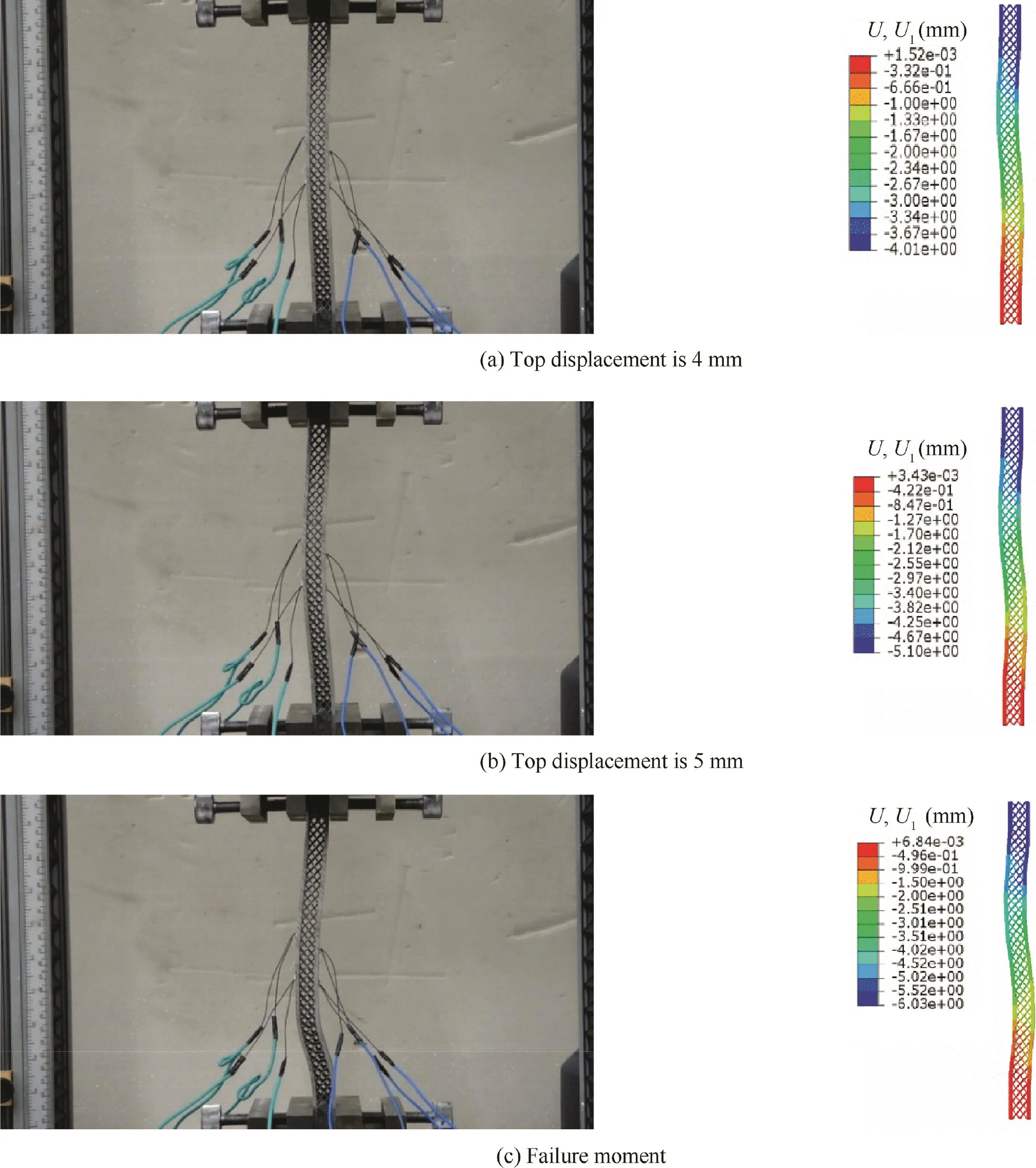
Fig.11 Comparison of deformation behaviors for in-plane compression test.
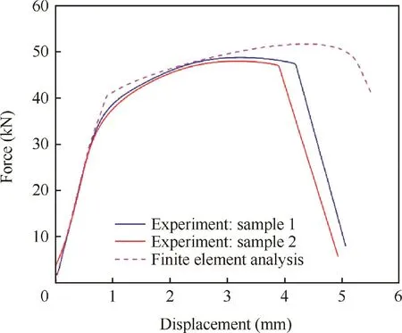
Fig.12 Force vs displacement curves for in-plane compression test.
5.2.Introduction of imperfections into numerical model
Before analysis of the cylinder,the method how to model the three kinds of imperfections in Section 4 is briefly introduced.Shape imperfection is often introduced into the finite element model using the buckling mode by eigenvalue buckling prediction in advance.20In this section,two kinds of buckling modes including skin dimpling and macro buckling are introduced,as shown in Figs.13(a)and(b).Both of them assume that the maximum derivation of the cylinder radius is 0.2 mm.
According to the observation in Section 4,the maximum surface roughness is considered to be 100 μm.This value is taken as the deviation of both the skin thickness and the strut radius.For instance,the skin thickness which standard value is 1.05 mm is assumed to vary in a segment from 0.95 mm to 1.15 mm.Then,by dividing the segment into 10 intervals,10 discrete thicknesses are generated and then randomly assigned to all the shell elements through Python.Fig.13(c)shows the skin’s thickness imperfection in a part of the cylinder.Similarly,the strut’s radius imperfection is introduced into finite element model,as shown in Fig.13(d).This method has been adopted by Karamooz Ravari et al.21and proved to be able to exactly predict the elastic property of lattice.Both thickness imperfection and radius imperfection are randomly generated three times to investigate the possible influence caused by imperfection position.
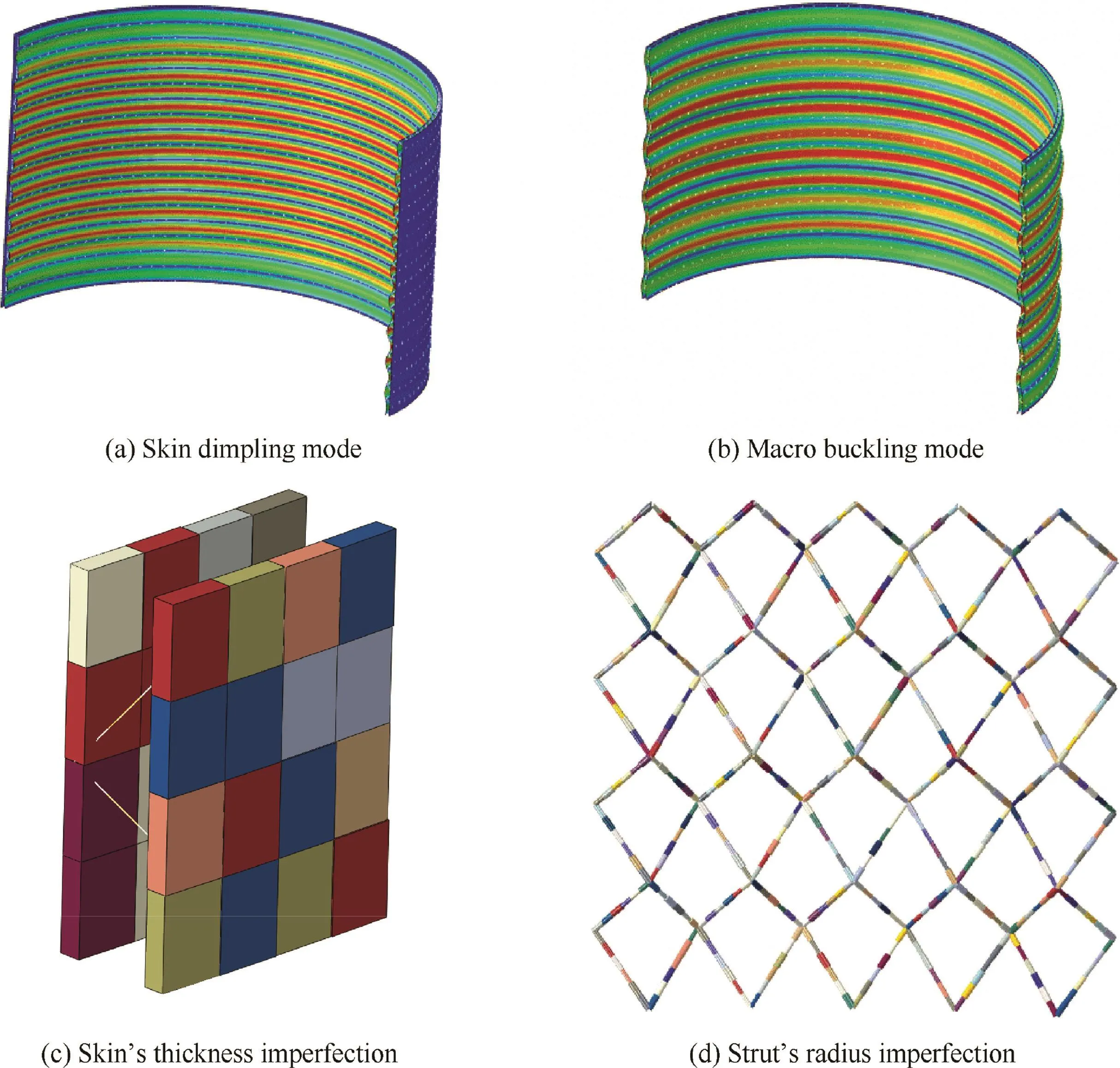
Fig.13 Introduction of imperfections into finite element model for lattice sandwich cylinder.
5.3.Finite element analysis for innovative lattice sandwich cylinder
As in Section 5.1,the skin and the strut in the finite element model of the lattice sandwich cylinder are simplified as shell element and beam element.Each strut has 6 beam elements and each side of the skin among a single cell has 4×4 elements.Therefore,the total model has 69120 shell elements and 51840 beam elements.The multi-point constraints are applied in the upper ends,and the bottom end is pinned.Both geometry nonlinear and material nonlinear behaviors are considered.The whole model is shown in Fig.14.
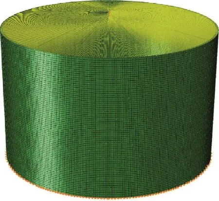
Fig.14 Finite element models for lattice sandwich cylinder.
Table 3,Figs.15 and 16 show the influence of various imperfections on the bearing capability of the cylinder.Ignoring any imperfection,the cylinder is able to carry 614.8 kN.There are 14.7%error compared with analytical solution705.4 kN in Section 3.3 that is may be partly caused by stress concentration near the upper or bottom end.Among all the kinds of imperfections,no matter how to be distributed,both the skin’s thickness imperfection and the strut’s radius imperfection have little influence not only on the bearing capability but also on the failure area that always appear near the ends,as shown in Figs.15(d)and(e).

Table 3 Bearing capability of innovative lattice sandwich cylinder with various imperfection.
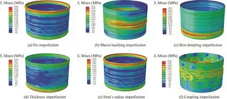
Fig.15 Failure modes of innovative lattice sandwich cylinder with various imperfections.
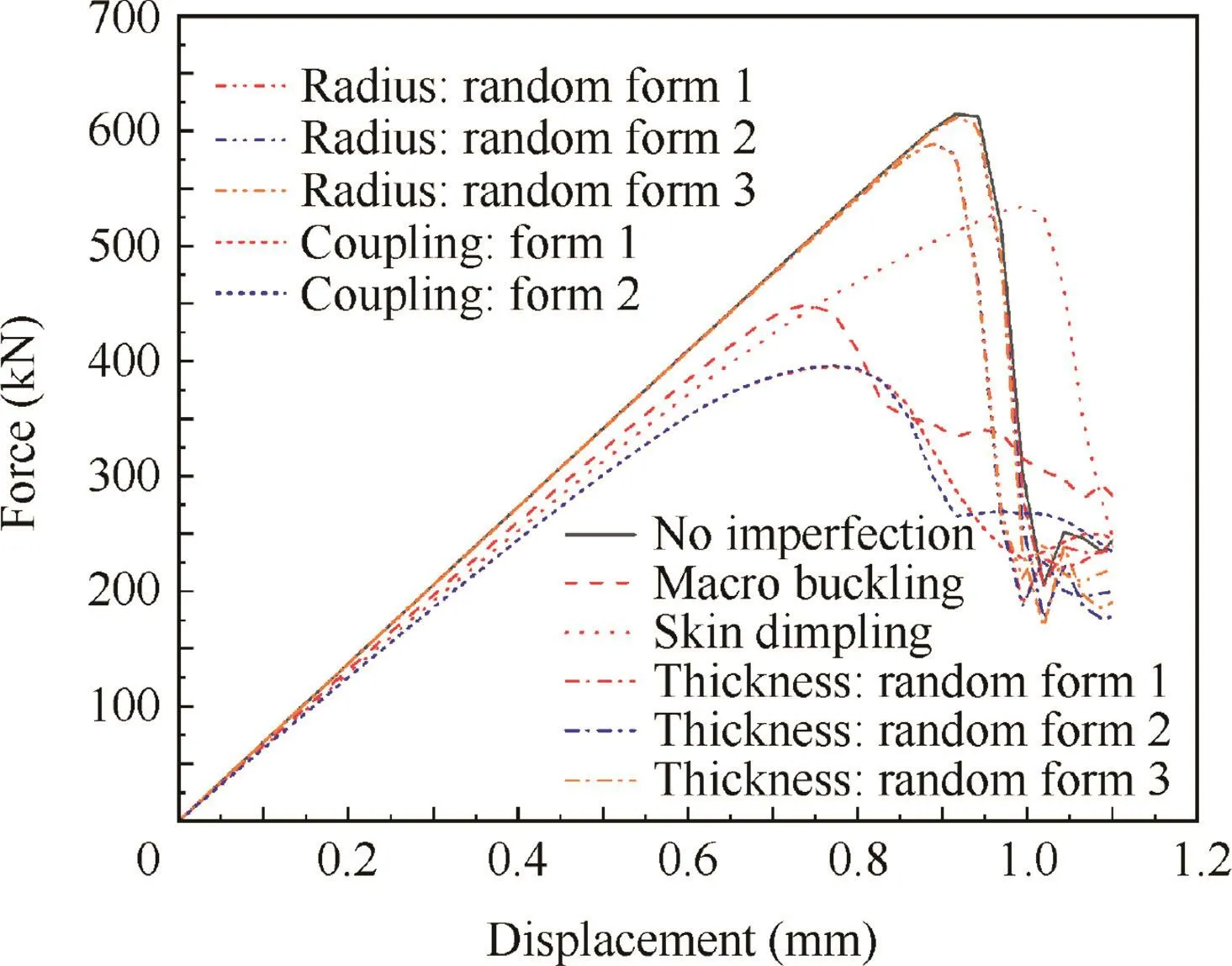
Fig.16 Force vs displacement for innovative lattice sandwich cylinder.
However,both kinds of shape imperfections can seriously affect the bear capability by reduction of 27.0%and 13.1%for macro buckling imperfection and skin dimpling imperfection.There is some difference between them because that the macro buckling mode changes the skin shape at both sides while the skin dimpling mode changes that at only one side.Meanwhile,the failure areas appear in the middle of the cylinder as shown in Figs.15(b)and(c),no longer at the ends.Moreover,Fig.16 indicates that the stiffness of the cylinder is reduced by both shape imperfection while remaining for the skin’s thickness imperfection or the strut’s radius imperfection.
In order to investigate the effect of other imperfection forms,the coupling imperfection is generated by composing macro buckling imperfection,skin dimpling imperfection,the first random distribution of skin’s thickness imperfection and the first random distribution of strut’s radius imperfection.Considering that shape imperfections cause the tremendous effect of the bearing capability,two coupling forms are composed,where the skin dimpling imperfection is imported in contrary direction.From Table 3 and Fig.16,we can know that the two coupling forms produce little difference,both decreasing around 35.6%bearing capability.However,it is interesting that the wave-shape failure is presented,difference from other imperfection forms.It should be pointed that the composition results in that the maximum derivation of the cylinder radius is up to 0.4 mm.From this point of view,macro buckling mode may best ill the most serious imperfection.
6.Conclusions
Considering the constructability with SLM processing,an innovative lightweight sandwich cylinder is optimized designed where the core is composed by pyramidal lattice.Finite element analysis is then adopted to simulate the mechanical behavior of the lattice sandwich cylinder.The main conclusions are as follows:
(1)Finite element method has been firstly used to simulate the lattice sandwich plate under in-plane compression test.Its applicability is proved by the high consistency of both the deformation behavior and the bearing capability between numerical results and test results.
(2)Among the common imperfections,the skin’s thickness imperfection and the strut’s radius imperfection are particularly brought by SLM processing,while they have little influence on the bearing capability of the lattice sandwich cylinder.It is proved that the novel processing cannot reduce the bearing capability than the traditional subtractive manufacturing.
(3)As for traditional cylinder,shape imperfections including macro buckling mode and skin dimpling mode have serious influence on the bearing capability of the innovative cylinder.Therefore,both the internal radius and the outer radius should be carefully controlled and measured to guarantee enough bearing capability.
(4)After introducing several typical imperfections in this paper,it is estimated that the lattice sandwich cylinder is able to carry 396 kN or even more load.This is approximate to the limit load of the initial CFRP cylinder,while its weight can be reduced by 25%or even more.This result proves that the innovative lattice sandwich cylinder is more effective.
Acknowledgments
The present work was supported by the National Natural Science Foundation of China(No.11602147),and the National Key Research and Development Program(No.2017YFB 1102800).
杂志排行
CHINESE JOURNAL OF AERONAUTICS的其它文章
- Recent development of casing treatments for aeroengine compressors
- Recent advances in physical understanding and quantitative prediction of impinging-jet dynamics and atomization
- General aspects on structural integrity
- Application of reliability technologies in civil aviation:Lessons learnt and perspectives
- FEC design for remote control and data transmission of aeronautic and astronautic vehicles
- Performance limitations in trajectory tracking control for air-breathing hypersonic vehicles
