A-USC and Double Reheat Steam Turbines
2019-01-03
(Steam Power Systems,General Electric,Baden,Switzerland,ivan.mcbean@ge.com)
Abstract:Environmental pressures and economic requirements have led to a drive to ever increasing steam parameters to further increase steam turbine cycle efficiencies.This poses a number of challenges:plant architecture,steam turbine design and turbine material requirements.GE has been developing USC technology for more than 18 years and has many reference plants.The limits on inlet pressure and temperatures have been challenged as the technology and product development has proceeded.This paper discusses some of the options on how plant efficiency can be increased and some of the related challenges.The performance difference between a single reheat and double reheat is quantified based on a simplified thermodynamic model.
Keywords:Steam Turbines,High Temperature,Efficiency,A-USC,Double Reheat
Nomenclature
HRHeat Rate[-]
HEnthalpy[kJ/kg]
ṁ Massflow[kg/s]
1 Introduction
In the recent decades in the steam turbine industry,not only has there been a further development of steam parameters,but different cycles have been employed with multiple reheat stages.This paper investigates some of these aspects,including the sensitivity of performance to inlet parameters,and the comparison of different reheat configurations in terms on the impact of performance.
Over the past 50 years,the inlet parameters have developed from supercritical,540°C and 240Bar in the 1960's and 1970's,and then in the late 1990's Ultra Super Critical(USC)conditions at 600°C(Tominaga et al 2017,Deckers et al 2006)[1-2].Most recently,concepts have been developed for advanced USC(AUSC)700°C and 350Bar.
There have been two main ways of improving cycle efficiency in conventional steam turbine plants.One is to increase inlet parameters to the high-pressure turbine,the other is to include reheat stages,where steam is taken from the exit of the HP turbine and reheated in the boiler.Additional reheat stages in a steam cycle improve performance,but also add significant complexity for both the steam turbine train and the steam turbine plant.For the steam turbine train,an additional module or casing is required,including additional safety and control valves.For the steam plant,in addition to the control system required for the valves,further pipework is required to the boiler and within the boiler or steam generator.The cycle performance benefit of every additional reheat stage needs to be significant to justify the additional turbine hardware and plant complexity.
The major limitation on the inlet steam parameters is the mechanical integrity of the turbine and associated plant components.To cope with these elevated conditions,the mechanical design proceeds by increasing casing wall thicknesses and blade size.However,for a given component,once a certain level of conditions is reached,it is required to change to a different material,one which can better cope with the elevated conditions.
The development of high temperature materials requires significant investment from manufacturers.This is because the tests needed to prove the suitability of these materials,as well as to obtain data for design,require experiments involving years of duration at high temperatures.The energy intensive and time-consuming experiments have been the subject of a number of government supported research consortiums.In Europe,for example,there was the Thermie AD700 project(Bregani et al 2005)[3]involving mainly European steam turbine manufacturers.In North America,there was a similar project supported by the Department of Energy(Purgert et al 2016)[4]to develop alloys for steam turbine components for higher temperatures.There have also been efforts from individual manufacturers(Tanaka 2012)[5].
The use of nickel based alloys is widespread in other industries,including gas turbines for power and aviation.The research projects were essentially a technology transfer to steam turbines.What differentiated the steam turbine applications were the size of the components,the specific conditions,and the required lifetime(Blum and Vanstone,2005)[6].It has been shown that existing design rules and design principles cannot be simply applied to plants with higher steam parameters(Lückemeyer,2012)[7],in particular the understanding of long term creep behavior was important for the mechanical integrity and design.To obtain the required material data,test specimens of representative shape and size were employed in the tests.Manufacturing trials were also conducted for the larger components such as the rotors and inner casings,to ensure that the material properties could be achieved for the larger size.
This paper has two main parts.The provides an overview on the influence of higher inlet parameters on the turbine design.The second part investigates and quantifies the performance for a range of inlet parameters,and compares a single and double reheat cycle.
2 Turbine Train Design
A typical modern steam turbine train involves an HP,an IP and a single or multiple LP turbine modules.USC designs usually employ a single reheat at the outlet of the HP turbine.There are many important design aspects for steam turbines operating at elevated inlet pressures and temperatures.Broadly there are two principal areas of focus-materials and local stress relieving features.Other strategies have been considered to enable operating at higher inlet parameters-including film cooling and increasing stage loading to more quickly reduce the temperature level in the flow path.However,both strategies reduce efficiency,and film cooling can significantly increase complexity,cost and maintenance effort.
Designing for higher temperatures does not change the turbine train layout significantly.Existing design methods and systems can be used.New material data are required,but these can be easily implemented within the design systems.For a double reheat train,a second intermediate pressure turbine is added,as shown in Figure 1.
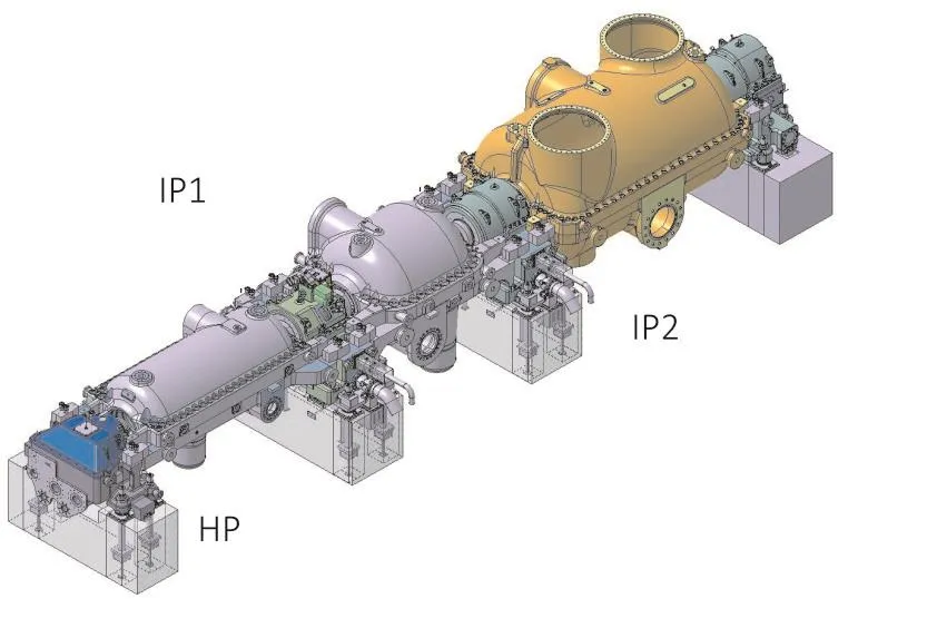
Fig.1 Turbine train for a double reheat configuration(without LP Modules)
As the inlet parameters increase,more and more of the steam path components need to be made from expensive nickel alloys.Given that only part of the HP and the IPs are subject to the higher temperatures,it makes sense to employ them in the flowpath,rotor and casing design where they are necessary.Key qualities of high temperature materials for steam turbines include good creep rupture,fatigue and creepfatigue properties.The Nickel based Alloy 617 is a good example of a material having these types of qualities(Erhardt 2014)[8].
One key enabling technology is rotor welding,which enables a single turbine rotor to be made from multiple forging ingots.This technology has been developed in the 1930's(Frey 1941)[9]and was initially needed to realize larger drum type rotors,where a complete rotor was beyond the size that could be forged.Subsequently this technology was further developed to enable the welding of dissimilar materials.This enables the more expensive material to be employed only in regions of higher temperature.Examples for an HP and IP rotor design are shown in Figure 2 and Figure 3.

Fig.2 Example of an HP turbine design with two different rotor materials
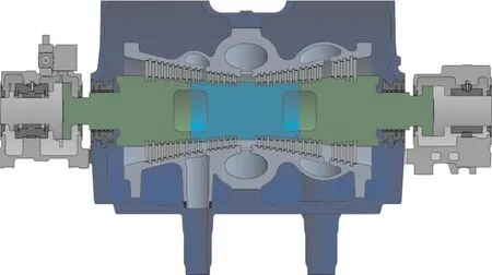
Fig.3 Example of an IP turbine design with two different rotor materials
A second aspect of material behavior is creep.Depending on the material,creep may begin at temperatures above 450℃well below the inlet temperature of a typical USC plant.Creep is the plastic deformation of a material where it is operated at elevated temperature for extended periods.The major problem of creep is that the component deforms slowly over time,therefore to a stress distribution in the component which may differ significantly from when the unit was commissioned,and the original design intent.The design needs to be checked to ensure that the total creep deformation over the lifetime of the component involves an allowable stress level in the component and the surrounding sub-assemblies.If the component cannot be redesigned to provide sufficient lifetime in terms of creep,it may be required to change to a more creep resistant material.
In the materials development projects mentioned in the introduction,detailed studies were made into the appropriate selection of materials at elevated steam conditions.The issues related to the material selection and material behavior are specific to the component and the associated thermal loads stresses,so the project focused on specific components in separate studies.
In the boiler tubing,the thermal expansion behavior is important,as well as oxidation and corrosion resistance(Blum and Vanstone,2005)[6].Despite this,to obtain good heat transfer characteristics,it was found the good steam quality in the feedwater was very important for sustained plant performance.For superheating tubing,both austenitic and an at that time new alloy inconel were investigated,with the focus on the improved resistance to corrosion.
For thick walled components,such as casings and rotors,maintaining material properties throughout the component at the larger size is key for mechanical integrity and lifetime.It was not clear at the outset that sufficient material properties could be achieved with such large components.Nine different alloys were investigated and the suitability was assessed and compared.Most of the materials behaved as expected,although for some,it was required to change the production process,or employ or modify the heat treatment process.For rotors,the weldability of the various materials was a focus.To weld dissimilar materials,the manufacture of the weld joint involved the use of a nickel based filler material,and a narrow gap TIG process(Blum and Vanstone,2005)[6].
Steam turbines are developed and customized for a specific plant layout,and for specific customers.To do this in a cost effective and timely manner,complex design systems have been established by many manufacturers(McBean,2017)[10-11].Blading geometries,and the rotor contour and casing contour for each turbine module have been parameterized to allow for adaptation of the blading design for particular thermodynamics.Whilst this works well at moderate temperature and pressure levels,at the inlet sections of HP and IP turbines,the elevated temperatures and pressures may lead to local stresses in the blading attachments that are close to or exceed the allowable level.For these situations,special design features may be required,for example more stress tolerant root attachment shapes,which may lead to higher manufacturing costs.As USC applications have become more common,these special features have also been implemented in the flowpath design software,and applied routinely as required according to the design rules.
3 Steam Turbine Plant Model
In this section,a simple steam plant model is introduced.A modern steam turbine plant is very complex.There are many different components which are key in modelling the plant performance,including the boiler,multiple steam turbine modules,valves,reheat lines,the condenser and preheater chains.To predict the performance accurately these components should be modelled in detail.This is standard procedure in the industry and every new steam plant is modelled in such a way.However,to understand the sensitivity of the plant performance on inlet parameters,a simpler approach has been taken,to remove the influence of components which may be moving to an off-design condition,biasing the results of the investigation.With the simplified approach,the plant can be assumed to be optimized for those specific conditions and configuration.This is useful in defining an ideal performance improvement from an existing,baseline USC configuration.
The conventional way of defining or measuring steam turbine plant performance is the steam rate or heat rate.This compares the amount of thermal energy input into the cycle,compared to the generator output.Steam rate is the usual measure of performance where the turbines are operating from at a single inlet temperature and pressure and discharging all of this flow at another pressure.The heat rate definition of performance involves an algebraic sum of all incoming and outgoing heat flows from the steam generator[ASME,2006][12].In the simplified cycle considered here,there is no preheater chain,and the only additional flows are the reheat stages.
The heat rate is therefore defined:

The change in enthalpy in the feedwater line is calculated based on constant LP exit conditions,with a constant pressure loss assumed in the steam generator.This has a relatively small contribution to the overall heat rate,and there is no preheater chain in the model.
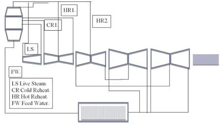
Fig.4 The thermodynamic layout of a typical double reheat USC plant
In this generic study,efficiencies were chosen arbitrarily at 94%for the HP,96%for the IP and 92%for the LP,which are representative for modern steam turbine designs.The present study involves different pressure ratios across the turbine sections,it was therefore decided to use a polytropic efficiency definition,to remove the reheat influence from the comparison.The reheat effect is due to the divergence of the pressure lines in the Mollier diagram.In the present investigation,HP turbines with pressure ratios from 5 to 2 are compared,and in the IP section for the double reheat case,pressure ratios from 12 to 2 are part of the study.A short investigation was performed into this influence,using the industrial IAPWS steam formulation as shown in Figure 5.The diagram was formulated by assuming a particular expansion and a polytropic efficiency,then calculating an isentropic efficiency for the same inlet and exit conditions.For example,for an HP at an efficiency level of 94%and a pressure ratio of 4.5,if the turbine with which we are making a comparison is at a pressure ratio of 1.5,then we can expect an influence of 0.68%in terms of the reheat effect.
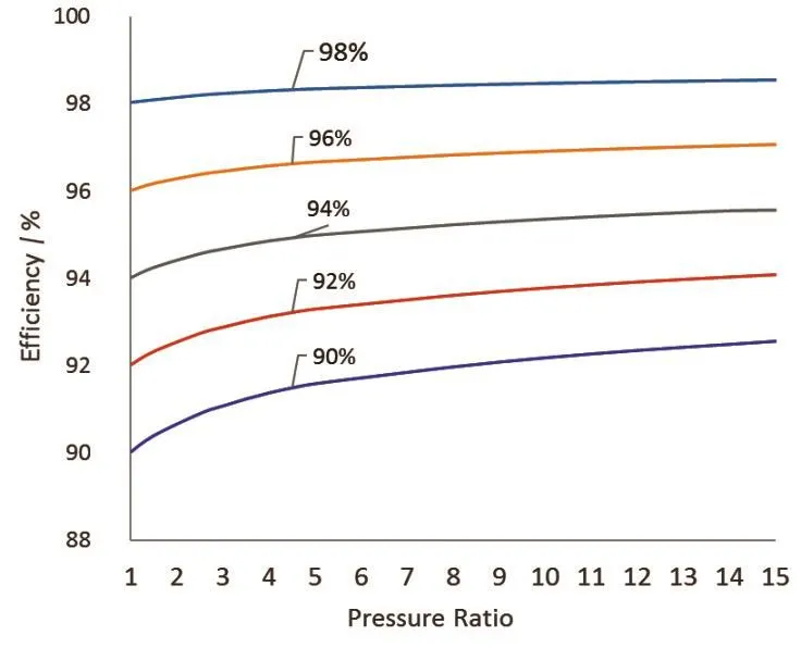
Fig.5 Influence of the reheat effect on the efficiency for an isentropic efficiency assumption
At the LP turbine exit,conditions were held at the same pressure for all cases.This led to a range of exit wetness levels between 8%for the highest temperature cycle,to 15%for the lowest conditions.To account for the impact of the variation of LP exit wetness on performance,a Baumann factor was employed in the LP performance calculation.
4 Influence of Different Cycles on Performance
The cycle model in the previous section was investigated with different inlet parameters,for both a single reheat and a double reheat cycle.The study was conducted so that the net heat input to each of the cycles was always the same,for both the single and double reheat cases.The massflows were varied in the overall cycle to ensure this.Despite the same heat input,this led to a different power output to a baseline case(with inlet conditions of 250Bar and 600°C),as shown in Figure 6 and Figure 7 for single and double reheat cycles,respectively.They have a similar sensitivity to inlet conditions.For example,an increase of 50°C at the HP inlet leads to an increase in power of 0.9%,and an increase in pressure of 50Bar leads to an increase of 2.5%for a single reheat plant.
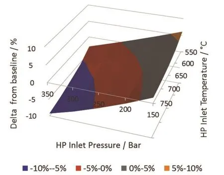
Fig.6 The dependence of heat rate on inlet steam parameters for a single reheat cycle

Fig.7 The dependence of heat rate on inlet steam parameters for a double reheat cycle
The relative performance of the double reheat and single reheat cycles were also compared in terms of power output in Figure 8.The power output increase for the double reheat compared to the single reheat is comparable to the power output increase due to an increase in HP inlet temperature of 50°C.
The implementation of double reheat brings considerable complexity and extra cost to the plant layout.Higher steam parameters also require more costly high temperature materials,increasing the cost of the HP and IP modules,as well as valves and the piping.To choose the best economic tradeoff between increased steam parameters and a double reheat cycle,the cost of electricity production including plant running costs production,compared to the extra investment in the plant equipment need to be compared.Other factors may also play a roll.The thicker the casings required with higher steam parameters may require longer start up and shut down procedures-a double reheat solution at lower may be potentially operated in a more flexible manner compared to an equivalent high temperature design.

Fig.8 Comparison of single and double reheat power output for a range of HP inlet parameters
5 Conclusions
An overview of the design challenges for high temperature steam turbines designs has been presented.Some of the issues surrounding materials and design were shown.An investigation was conducted into the influence of HP inlet parameters and cycle configurations for USC type steam turbine plants,for a simplified thermodynamic model.Typically,more complicated models are employed to design steam plants,however sometimes this complexity makes it difficult to draw generic conclusions on fundamental aspects of plant performance.
For the steam cycle with standard USC conditions of 600°C and 250 Bar,the double reheat configuration provides around 2.3%higher power than the single reheat.Increasing the USC plant from these standard conditions to 700°C and 300Bar increases output power by around 4.4%.The power output increase for the double reheat compared to the single reheat is comparable to the power output increase due to an increase in HP inlet temperature of 50°C.However,higher steam parameters alone may not provide the best solution.The increase in plant performance of the double reheat provides a viable alternative where higher plant efficiency is required and plant investment cost is not a big consideration.
GE has been involved in the development of USC and A-USC technology over the past two decades.The company has the steam turbine technology and plant technology,along with associated design systems,to optimize the design and enable customers to balance the competing aspects of investment cost and performance for advanced ultra-supercritical steam parameters.
