Radial Vibration Characteristics of a Double-overhung Rub Rotor*
2018-11-13
(Department of Mechanical Engineering,Tsinghua University,Beijing,China,Email:luwenxiu@mail.tsinghua.edu.cn)
Abstract:This paper investigates the vibration characteristics of a double-overhung rub rotor considering gyroscopic couples and slanting contact between rotors and stators.This paper deduces a new contact model according to slant contact between rotor and stator,which close to real rub condition,and compared with simple contact model.With rotating speed and support span changing,the dynamic behaviors of rotors are simulated by the fourth Runge-Kutta method.The results illustrate that gyroscopic couples and slant contact model can lead to rub occurrence at a lower speed compared with no gyroscopic couples or slant contact.Resonance has a huge effect on radial displacement and frequency spectrum of disk,and in resonance interval the frequency components are complex.At the same rotating speed,support span has a monotonous effect on amplitude of radial displacement.These results might provide some reference to estimate whether rubbing occurs and help to control rubbing force.
Key Words:Overhung rotor,Rotor-stator rub,Slant contact model,Nonlinear vibration,Radial characteristics
Nomenclature
aSupport span
b1,b2Left Cantilever length,right cantilever length
EElasticity modulus
IInertia moment
x1,y1Dynamic displacement in the x-direction,y-direction of left disk
x1,y1Dynamic displacement in the x-direction,y-direction of right disk
r1,r2Radial displacement of left,right disk
θ1,ψ1Rotation about ox,oy of left disk
θ2,ψ2Rotation about ox,oy of right disk
pxz1,pxz2Forces acting on left,right disk in x-oz plane
pyz1,pyz2Forces acting on left,right disk in y-oz plane
Mxz1,Mxz2Moments acting on left,right disk in xoz plane
Myz1,Myz2Moments acting on left,right disk in y-o-z plane
δ1,δ2Clearance between rotor and stator
EcEquivalent contact stiffness
Fn1,Fn2Normal rub force of acting on left,right disk
Fτ1,Fτ2tangent rub force of acting on left,right disk
α1spatial slant angle of disk geometric cen ter
δ1_0,δ2_0displacement of left,right geometric center
h1,h2Half thickness of left,right disk
Rd1,Rd2Radius of left,right disk
Rs1,Rs2Radius of left,right stator
δm1_1,δm1_2Invasion depth between left disk and stator
Fe1external force acting on left disk
Me1external moment acting on right disk
fFriction coefficient
ΩRotating speed
c1,c1Damping coefficient
1 Introduction
Turbochargers are widely employed in sorts of vehicles.With higher demands for improvement of performance and reduction of emission,turbochargers are always in pursuit of high power and low energy consumption by high rotating speed and high fuel efficiency.A turbocharger consists of a turbine and a compressor;both of them are overhung on two ends of a shaft respectively.This structure is liable to triggering system vibration and increases the probability of rubbing occurrence.
Many efforts have been made to study severe vibration,instability,rubbing and other malfunction caused by mass imbalance,assembly errors,shaft crack,thermal bending and so on.Turbochargers usually show sub-synchronous vibration,which can result in noise,collision and rubbing,as Homes(2004)[1]studied.Kirk et al.(2009)[2]investigated imbalance influence on sub-synchronous vibration amplitude,and verified that compressor imbalance could suppress the first mode instability.Liang(2015)[3]put forward a predicting expression to estimate the sub-synchronous whirl frequency of semi-floating ring bearings and generalize to the rotor-SFRBs.Bai(2010)[4]studied a liquid fuel turbo-pump’s performance with a flexible support,and explained the characteristics of the sub-synchronous motion of a turbo-pump rotor with flexible support.Schweizer(2009)[5]investigated a turbocharger supported in full-floating ring bearings,and revealed causes that generate the 1st,2nd,3rd,and the 4thmain frequency.Castro et al.(2008)[6]verified the effects of unbalance and rotor arrangement on the instability threshold,and pointed out the characteristics of whirl instability and whip instability in horizontal and vertical rotor.Gunter(2005)[7]studied the linear and nonlinear dynamical characteristics of turbochargers in floating bush bearing,and compared with the work of Li(1982)[8],unbalance response to the third bending critical speed was evaluated.At high rotating speed gyroscopic effect plays an important role in rotordynamidcs,and it should be taken into account in rotordynamics computation(Hung Nguyen-Schafer,2012)[9].Liao et al.(2009)[10]established a finite element model of turbocharger considering the effect of gyroscopic couples and floating bearings stiffness,and analyzed the effects on critical speeds and vibration mode.In innovative computational model,Novotny(2017)[11]described some principles in fast simulation of turbochargers.
I pulled the boy up off the ground and helped him back to his house which was about two blocks down the street from the school building. When we reached his home his sister told me that her brother was deaf but that he was not dumb like the two bullies said. That he was very smart but could not say or hear anything. I told her that he did make a sound when the bully3 kicked him in the back. She told me that I must be mistaken because all her brother s vocal4 cords had been removed during an experimental surgery, which had failed.
From above we can find that,previous work covers little radial vibration research.This paper simplifies a turbocharger to a double-overhung rotor system,and establishes a new contact mode and concentrates on studying the radial vibration characteristics.The numerical method is employed to solve equations.The effects of gyroscopic couples and slant contact,rotating speed,support span are investigated by time series,frequency spectra,and rotor locus.And at last,some conclusions are drawn.
2 Dynamic model of the system
The schematic of double-overhung rotors system is shown in Fig.1~3.The system can rotate about theOz-axis with a constant angular velocity,Ω.The two disks can also rotate aboutOxandOyaxes byθ˙andψ˙,respectively.And we state the sense of the rotations is such that positive values of and cause a right-hand screw to advance alongOxandOy,respectively.
In order to study this system,the following assumptions are made:
1)The rotors and bearings are rigid and symmetric
2)The shaft cross-section and material properties along its length are uniform,i.e.Iy=Iz=I
3)The axial and torsional vibration are negligible
4)The mass of shaft is negligible

Fig.1 Model of rotor system

Fig.2 Force diagram in x-o-z plane
2.1 Stiffness Coefficient for Shaft System Considering Gyroscopic Effect
This shaft is simply supported by two short bearings with a distance ofa,which are in the middle of two disks.Left disk is located a distanceb1from left bearing and another disk isb2from the other.
In x-o-z plane,according to force diagram,flexibility matrix and stiffness matrix can be derived.
Flexibility matrix is

Stiffness matrix can be derived from Eq.(1).
Similarly,iny-o-zplane,
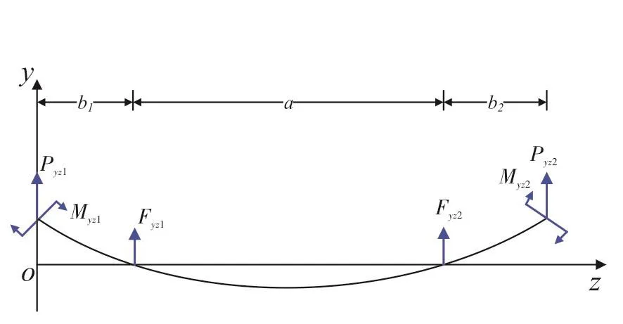
Fig.3 Force Diagram in y-o-z Plane
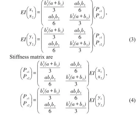
Flexibility matrix is

Stiffness matrix of y-o-z plane can be obtained from Eq.(2).
2.2 Stiffness Coefficient for Shaft System Without Considering Gyroscopic Couples Effect
Without considering the influence of gyroscopic couples,flexibility matrixes are
2.3 Contact Model Without Considering Slanting Contact or Gyroscopic Effect
As shown in Fig.4,for left disk and stator,we define that the radius of left disk isRd1,the thickness of the disk is 2h1,the radius of left stator isRs1,the gap between disk and stator isδ1=Rs1-Rd1.When rubbing occurs,the radial impact forceFn1and the tangential rub forceFτ1can be expressed respectively as:

wherer1is displacement of the left disk andr1>δ1,,Ecis contact stiffness,fis friction coefficient.
For right disk and stator,it can be derived that,

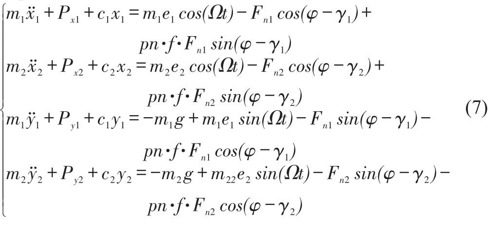
Then,the governing equations of the system can be expressed as
2.4 Contact Model Considering Slanting Contact and Gyroscopic Effect
As mentioned in assumptions,axial displacement is negligible.Thus,geometric centers of rotors are always in the same vertical planes.
As shown in Fig.5,for left disk and stator,we define that the spatial slant angle of geometric center isα1,the displacement of geometric center is,then,.So if invasion occurs,the depth between rotor and stator is.At opposite positon, if invasion occurs,the depth is.In conclusion,
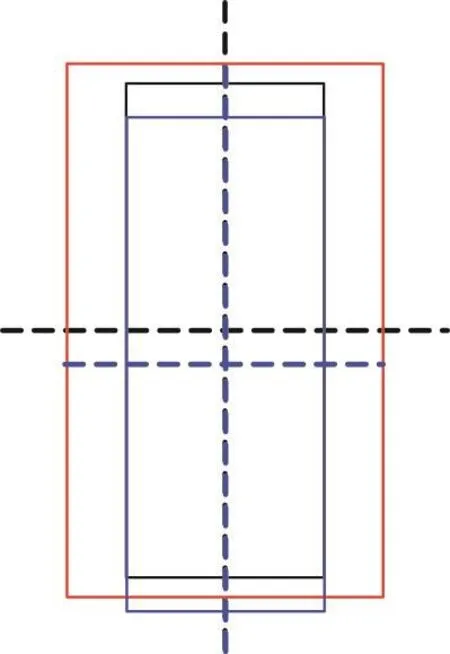
Fig.4 Plain Contact of Rotors

Fig.5 Slanting Contact of Rotors

There is rubbing between disk and stator whenδm1_1>0 orδm1_2>0,and there is no rubbing whenδm1_1<0 andδm1_2<0.
Similarly,for right disk and stator,

There is rubbing between disk and stator whenδm2_1>0 orδm2_2>0,and there is no rubbing whenδm2_1<0 andδm2_2<0.
Under circumstance of rubbing,there is assumption that the relation between invasion depth and displacement of disk is linear,namely,δ1(l)=l1tanα1,0≤l1≤L1,L1=δm1/tanα1.In the light of contact deformation between two cylinders(Popov,2017)[12],the external force istanα1l1dl1.So the radial force isFn1=Fe1cosα1,the ta-ngential force produced by friction isFτ1=fFn1,and the bending moment is.
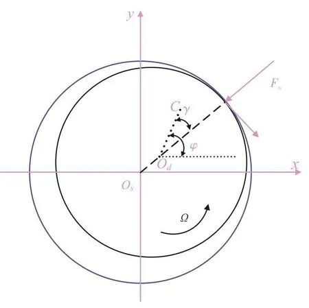
Fig.6 Forces in A Disk Cross-Section
Similarly,it can be derived for right disk.Gyroscopic effect is also taken into consideration,so the differential equations of motion for the system are:

where

3 Simulation Results and Discussion
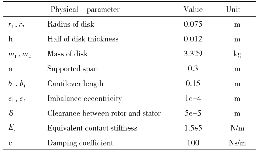
In order to study the response of Eq.(7)and Eq.(10),the fourth Runge-Kutta method is employed.The parameters are listed in Table 1.
Tab.1 Parameters of Rotor System
3.1 Effects of Gyroscopic Action and Slant Rubbing
The gyroscopic couples’effect is investigated in this subsection.The effect will bring about slant rubbing,as shown in Fig.5.Without considering this effect,the contact condition between rotor and stator is as shown in Fig.4.
As is shown in Fig.7,although the support span varies,taking gyroscopic couples into consideration,the occurrence of rub will bring forward,namely,the rub will take place at a lower speed compared with the case which without considering the effect of gyroscopic couples at any support span.As this figure illustrates,with the increase of rotating speed,the intermittent rub occurs firstly,with further increase,the continuous rub will occur.
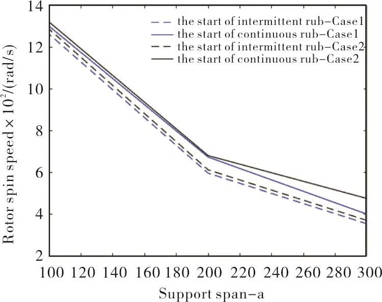
Fig.7 Dashed line-initial intermittent rub,solid line-continuous rub,blue line(case1)-with gyroscopic action and slant rubbing,black line(case2)-without gyroscopic action or slant rubbing.
At the very beginning of rubbing,the displacement of centroid of disk is smaller than the clearance between rotor and stator if gyroscopic couples and slant contact are taken into consideration,as shown in Fig.8(a).If not,the displacement of centroid of disk will be equal to the clearance at the moment of rubbing occurrence,as shown in Fig.8(b).
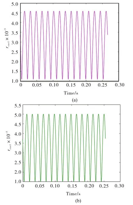
Fig.8 Pink line-with gyroscopic action and slant rubbing,Cyan line-without gyroscopic action or slant rubbing.
Gyroscopic couples also have effects on rubbing force.At the same rotating speed,they lead to rubbing force more seriously as Fig.9 shows,compared with no gyroscopic couples’effects.But gyroscopic couples have little effects on amplitude of radial displacement of disk vibration,as Fig.10 shows.

Fig.9 (a)ω=400 rad/s,(b)ω=600 rad/s,(c)ω=800 rad/s,(d)ω=1 000 rad/s
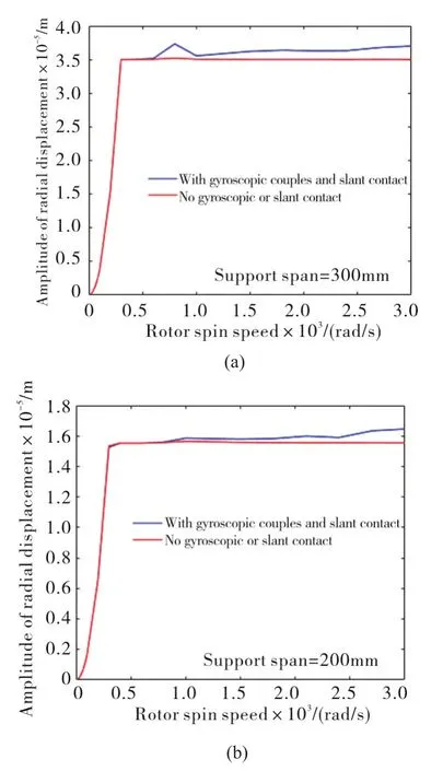
Fig.10 Amplitude difference
3.2 Effects of Rotating Speed
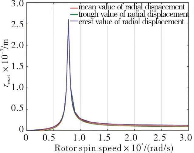
Fig.11 Radial displacement of disk
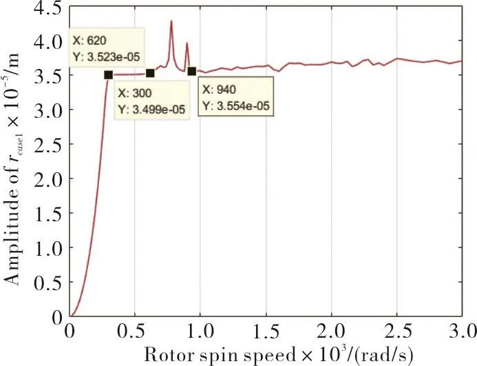
Fig.12 Amplitude of radial displacement of disk
Fig.11 shows that before resonance occurs,with the increase of rotating speed,radial displacement of disk becomes bigger.Behind the resonance frequency,the radial displacement becomes smaller and then tends to be stable.Fig.12 shows that amplitude of the disk vibration increases dramatically beforeω=300 rad/s,from 300~620 rad/s the amplitude levels off,from 620~940 rad/s,the range which resonance occurs,the amplitude varies sharply,and after 940 rad/s the amplitude increase slowly on the whole.Fig.13 shows that disk orbits at different rotating speed steady state always present different radius circles.

Fig.13 Disk orbits at different rotating speed
As is shown in Fig.14,before rub occurs,from 0~300 rad/s,frequency components of disk vibration are simple,just containing Ω.From 400 ~ 1000 rad/s,frequency components are complicated.At a higher speed,more than 1000 rad/s,frequency components become simple.

Fig.14 Disk orbits at different rotating speed
3.3 Effects of Support Span
When total length of shaft is fixed,with the increase of support span,namely with the reduction of cantilever length,the resonance will occur at a higher rotating speed,as Fig.15 illustrates.When support span is fixed,with the increase of rotating speed starting whit 0,the crest value increases more and more quickly before resonance occurs.After resonance,the values decrease sharply and then tend to be stable,with the same as Fig.11.But in the aspect of vibration amplitude of radial displacement,with the increase of support span,namely with the reduction of cantilever length,the amplitude of radial displacement is on progressive decline.Except in the resonance interval,at the same rotating speed,the larger support span is,the smaller the amplitude is,as Fig.16 shows.
From above,we can know that,we should lengthen support span,in other words,shorten cantilever length,to restrain the amplitude of radial displacement.And the crest value has a direct effect on rubbing force,so we can control this factor to change the rubbing force.

Fig.15 Disk radial displacement at different support span
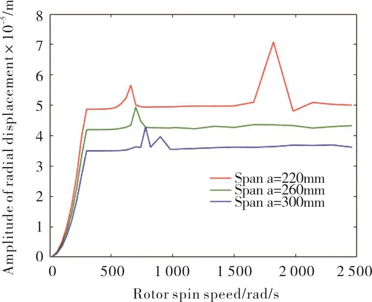
Fig.16 Disk vibration amplitude at different support span
4 Conclusions
In this study a new contact model is established.Effects of gyroscopic couples and slant contact,rotating speed,support span on dynamic behaviors of the system are investigated.Some conclusions can be drawn from the simulation results as follows:
1)Gyroscopic couples and slant contact can cause rub occurrence in advance,and make the rubbing forces more seriously.But it has little effects on amplitude of disk radial displacement at the same speed.
2)Resonance frequency has huge effects on radial displacement, near the resonance interval, frequency components are complicated, in other intervals the components are simple.
3)When the shaft length is fixed,with the increase of support span,except the resonance interval,the amplitude of disk radial displacement is decreasing monotonously.Resonance frequency has a huge effect on the crest value of disk radial displacements,and huge crest value can be avoided by adjusting support span.
